EP0038563A2 - Système optique à haute efficacité de couplage, en particulier pour un appareillage de mesure de l'atténuation par la méthode de rétrodiffusion - Google Patents
Système optique à haute efficacité de couplage, en particulier pour un appareillage de mesure de l'atténuation par la méthode de rétrodiffusion Download PDFInfo
- Publication number
- EP0038563A2 EP0038563A2 EP81103035A EP81103035A EP0038563A2 EP 0038563 A2 EP0038563 A2 EP 0038563A2 EP 81103035 A EP81103035 A EP 81103035A EP 81103035 A EP81103035 A EP 81103035A EP 0038563 A2 EP0038563 A2 EP 0038563A2
- Authority
- EP
- European Patent Office
- Prior art keywords
- fibre
- optical system
- source
- optical
- light
- Prior art date
- Legal status (The legal status is an assumption and is not a legal conclusion. Google has not performed a legal analysis and makes no representation as to the accuracy of the status listed.)
- Ceased
Links
- 230000003287 optical effect Effects 0.000 title claims abstract description 21
- 238000005259 measurement Methods 0.000 title claims description 9
- 230000008878 coupling Effects 0.000 title claims description 8
- 238000010168 coupling process Methods 0.000 title claims description 8
- 238000005859 coupling reaction Methods 0.000 title claims description 8
- 238000000034 method Methods 0.000 title description 5
- 239000000835 fiber Substances 0.000 claims abstract description 34
- 239000013307 optical fiber Substances 0.000 claims description 5
- 239000011521 glass Substances 0.000 claims description 4
- 239000007788 liquid Substances 0.000 claims 1
- 239000004065 semiconductor Substances 0.000 description 5
- 238000012360 testing method Methods 0.000 description 4
- 230000000694 effects Effects 0.000 description 3
- 230000010287 polarization Effects 0.000 description 3
- 230000005540 biological transmission Effects 0.000 description 2
- 239000011248 coating agent Substances 0.000 description 1
- 238000000576 coating method Methods 0.000 description 1
- 230000008030 elimination Effects 0.000 description 1
- 238000003379 elimination reaction Methods 0.000 description 1
- 239000012530 fluid Substances 0.000 description 1
- 238000004519 manufacturing process Methods 0.000 description 1
- 238000012986 modification Methods 0.000 description 1
- 230000004048 modification Effects 0.000 description 1
- 230000005855 radiation Effects 0.000 description 1
Images

Classifications
-
- G—PHYSICS
- G02—OPTICS
- G02B—OPTICAL ELEMENTS, SYSTEMS OR APPARATUS
- G02B6/00—Light guides; Structural details of arrangements comprising light guides and other optical elements, e.g. couplings
- G02B6/24—Coupling light guides
- G02B6/26—Optical coupling means
- G02B6/28—Optical coupling means having data bus means, i.e. plural waveguides interconnected and providing an inherently bidirectional system by mixing and splitting signals
- G02B6/2804—Optical coupling means having data bus means, i.e. plural waveguides interconnected and providing an inherently bidirectional system by mixing and splitting signals forming multipart couplers without wavelength selective elements, e.g. "T" couplers, star couplers
- G02B6/2817—Optical coupling means having data bus means, i.e. plural waveguides interconnected and providing an inherently bidirectional system by mixing and splitting signals forming multipart couplers without wavelength selective elements, e.g. "T" couplers, star couplers using reflective elements to split or combine optical signals
-
- G—PHYSICS
- G01—MEASURING; TESTING
- G01M—TESTING STATIC OR DYNAMIC BALANCE OF MACHINES OR STRUCTURES; TESTING OF STRUCTURES OR APPARATUS, NOT OTHERWISE PROVIDED FOR
- G01M11/00—Testing of optical apparatus; Testing structures by optical methods not otherwise provided for
- G01M11/30—Testing of optical devices, constituted by fibre optics or optical waveguides
- G01M11/31—Testing of optical devices, constituted by fibre optics or optical waveguides with a light emitter and a light receiver being disposed at the same side of a fibre or waveguide end-face, e.g. reflectometers
Definitions
- the present invention relates to a high-efficiency optical system for coupling a light-pulse source, having a substantially rectangular emitting surface, with an optical fibre.
- the invention concerns an optical system for apparatuses designed to measure the attenuation characteristics of optical fibres by the back-scattering technique.
- semiconductor power lasers are generally used as light sources to effect certain measurements or tests on optical fibres; said lasers emit pulses that are focussed bylens systems or microscope objectives into the fibre input face.
- semiconductor lasers whose sizes are very reduced allows the manufacture of portable devices, that are particularly appropriate to effect field tests on the fibres.
- semiconductor power lasers have, as a rule, rectangular emitting surfaces that, if conventional optical systems are used can be coupled to fibres (that generally have circular cross sections), only with high losses and unsatisfactory exploitation of the numerical aperture ot the fibre.
- the literature does not offer special suggestions on how to ameliorate coupling efficiency between source and fiber in that kind of measurement.
- This problem is solved by the present invention that provides an optical system that presents high coupling efficiency between a source with a rectangular emission surface and a fibre with circular cross section and allows at the some time a reduction in spurious reflections.
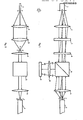
- a source 1 of light pulses suitable to attenuation measurements for instance a semiconductor laser, is located in a focus of a first spherical lens 2, or of a first system of spherical lenses such as a microscope objective; lens or objective 2 is followed by a pair of cylindrical lenses 3 and 4 arranged such as to have a common focus F and having the generatrices parallel to the major side of the emitting surface of source 1, that, as a rule, is rectangular.
- the second cylindrical lens 4 is followed in turn by a beam splitter 5 .
- beam splitter 5 transmits a portion of the power associated with the pulses emitted by source 1 towards fibre 7 under test, whose end face is located in the focus of a second spherical lens 6, or of a second optical system such as a microscope objective.
- beam splitter 5 re- fleets the pulses backscattered in fibre 7 and collected by objective 6, towards a collection system, schematized by lens 8; a photodetector 9, convertering light power into electric power is placed in the focus of said lens 8.
- the devices obtaining the attenuation values from the output electrical signals of photodetector 9 are not represented because they are conventional and are not of interest for the invention.
- Advantageously beam splitter 5 consists of a Glan-Thompson prism or of a Glan-Taylor prism; the purposes of this choice will become more apparent hereinafter.
- cylindrical lenses allow a source image to be formed at the fibre input end which image is better suited to the fibre characteristics from both the size and the emission angle standpoints.
- the two cylindrical lenses 3, 4 act as mere transparent bodies: under these conditions the parallel beam outgoing from lens 2 will go on parallel through lenses 3, 4 and beam splitter 5 and it will be focused by lens 5 at the input of fibre 7.
- the major side can be shortened with respect to actual source 1 and/or the minor side can be lenghthened; therefore the dissymmetry of said apparent source is reducedwith respect to the actual source.
- the emissionangle of the ray source is changed inversely to magnifications M', M". Therefore said magnifications ought to be chosen such as to adapt in the best possible way the radiations emitted in the two planes to the fibre numerical aperture.
- Figures 1, 2 schematically shows how the images of three points A, B, C of the major side of source 1 and of two points D. E of the minor side are formed.
- Efficiency is further improved by using a Glan prism as the beam splitter which transmits light polarized in one direction and reflects light polarized in orthogonal direction. This feature permits also a partial elimination of spurious pulses reflected at the fibre input.
- the light of a semiconductor laser is at least partially polarized, and then by a suitable arrangement of the prism and of source 1 a transmission coefficient of about 75% can be obtained instead of the transmission coefficient of about 50% attainable by a conventional semitransparent mirror.
- backscattered light is depolarized, and therefore 50 % of it (corresponding to the polarization perpendicular to that of the incident beam) is reflected by the prism; on the contrary most of the light reflected by the fibre end face maintains the polarization imposed by prism 5.
- the backscattered light will be reflected by the prism towards the measurement apparatuses; as to the light reflected by the fibre and forming the spurios pulse, the part thereof which has maintained the polarization will pass through the prism and therefore it will not affect the measurement.
- the fibre end could be introduced into a cell matching the refractive index and eliminating spurious reflections like that described by the inventor and by B. Sordo in the paper "Experimental study of optical fibres attenuation by a modified backscattering technique", presented, at the third European Conference on Optical Communications, Kunststoff, 14-16 September 1977,.
- a glass plate 10 can be placed before the fibre input face, as shown in Fig. 3; owing to said plate, rays forming the reflected spurious pulse no longer come from a source located in the focus of lens 6; and therefore said rays will no longer focus on photodetector 9, of conveniently small size with consequent further reduction in the inconvenients due to spurious pulses.
- the above mentioned system has the advantage of being wavelength independent and less expensive.
- a drop 11 of index matching fluid placed between the glass plate and the fibre eliminates reflections from the fibre end face.
Landscapes
- Physics & Mathematics (AREA)
- General Physics & Mathematics (AREA)
- Optics & Photonics (AREA)
- Chemical & Material Sciences (AREA)
- Analytical Chemistry (AREA)
- Optical Couplings Of Light Guides (AREA)
- Investigating Or Analysing Materials By Optical Means (AREA)
- Testing Of Optical Devices Or Fibers (AREA)
Applications Claiming Priority (2)
| Application Number | Priority Date | Filing Date | Title |
|---|---|---|---|
| IT67634/80A IT1130802B (it) | 1980-04-23 | 1980-04-23 | Sistema ottico ad alta efficienza di accoppiamento in particolare per dispositivi di misura della attenuazione di fibre ottiche mediante retrodiffusione |
| IT6763480 | 1980-04-23 |
Publications (2)
| Publication Number | Publication Date |
|---|---|
| EP0038563A2 true EP0038563A2 (fr) | 1981-10-28 |
| EP0038563A3 EP0038563A3 (fr) | 1982-04-14 |
Family
ID=11304078
Family Applications (1)
| Application Number | Title | Priority Date | Filing Date |
|---|---|---|---|
| EP81103035A Ceased EP0038563A3 (fr) | 1980-04-23 | 1981-04-22 | Système optique à haute efficacité de couplage, en particulier pour un appareillage de mesure de l'atténuation par la méthode de rétrodiffusion |
Country Status (6)
| Country | Link |
|---|---|
| US (1) | US4412720A (fr) |
| EP (1) | EP0038563A3 (fr) |
| JP (1) | JPS56158932A (fr) |
| CA (1) | CA1150541A (fr) |
| DK (1) | DK160581A (fr) |
| IT (1) | IT1130802B (fr) |
Cited By (2)
| Publication number | Priority date | Publication date | Assignee | Title |
|---|---|---|---|---|
| EP0122953A1 (fr) * | 1983-04-23 | 1984-10-31 | ANT Nachrichtentechnik GmbH | Méthode pour déterminer le diagramme de rétrodiffusion d'un guide d'ondes lumineux |
| GB2220501A (en) * | 1988-07-06 | 1990-01-10 | Plessey Co Plc | Coupling waveguides using transverse cylindrical lenses |
Families Citing this family (38)
| Publication number | Priority date | Publication date | Assignee | Title |
|---|---|---|---|---|
| JPS57185410A (en) * | 1981-05-11 | 1982-11-15 | Kokusai Denshin Denwa Co Ltd <Kdd> | Optical coupler |
| FR2515811A1 (fr) * | 1981-11-03 | 1983-05-06 | Thomson Csf | Dispositif interferometrique de mesure de champ magnetique et capteur de courant electrique comportant un tel dispositif |
| US4676584A (en) * | 1983-06-22 | 1987-06-30 | Metatech Corporation | Fiber optic light coupling assemblies |
| JPS60120306A (ja) * | 1983-12-05 | 1985-06-27 | Nec Corp | レ−ザ集光装置 |
| US4678269A (en) * | 1985-12-10 | 1987-07-07 | Pace Nevlin C | Concentric light source to fiber coupling system |
| US4917453A (en) * | 1987-01-29 | 1990-04-17 | International Business Machines Corporation | Optical communication signal source |
| US4834485A (en) * | 1988-01-04 | 1989-05-30 | Pencom International Corporation | Integrated fiber optics transmitter/receiver device |
| JPH0315018A (ja) * | 1989-01-13 | 1991-01-23 | Dainippon Screen Mfg Co Ltd | 画像走査記録装置のレーザ露光装置 |
| ES2049961T3 (es) * | 1989-10-03 | 1994-05-01 | Ciba Geigy Ag | Procedimiento para el acoplamiento de la energia luminosa de un rayo laser a un cable de fibra optica y procedimiento de enfoque y control de la posicion del extremo del cable de fibra optica. |
| US5013120A (en) * | 1990-05-31 | 1991-05-07 | Conoco Inc. | Monochromator to fiber-cable coupling system |
| JP2604171Y2 (ja) * | 1991-05-15 | 2000-04-17 | 安藤電気株式会社 | 光源と光ファイバの結合器 |
| FR2688319B1 (fr) * | 1992-03-06 | 1994-12-23 | Thomson Hybrides | Coupleur optique a haute isolation. |
| US6130971A (en) * | 1998-08-06 | 2000-10-10 | Avanex Corporation | Fiber optic dense wavelength division multiplexer with a phase differential method of wavelength separation utilizing a polarization beam splitter and a nonlinear interferometer |
| US6253006B1 (en) * | 1999-10-28 | 2001-06-26 | Radiant Optics, Inc. | Directing and organizing lens means for a fiber optics network |
| US7125175B2 (en) * | 2003-05-01 | 2006-10-24 | Selex Sensors And Airborne Systems Limited | Optical coupling devices |
| DE102005061834B4 (de) * | 2005-12-23 | 2007-11-08 | Ioss Intelligente Optische Sensoren & Systeme Gmbh | Vorrichtung und Verfahren zum optischen Prüfen einer Oberfläche |
| WO2015093470A1 (fr) * | 2013-12-16 | 2015-06-25 | 日本電信電話株式会社 | Dispositif d'observation de surface d'extrémité |
| JP6555110B2 (ja) * | 2015-12-08 | 2019-08-07 | 富士通株式会社 | 光受信装置 |
| US10942257B2 (en) | 2016-12-31 | 2021-03-09 | Innovusion Ireland Limited | 2D scanning high precision LiDAR using combination of rotating concave mirror and beam steering devices |
| US11009605B2 (en) | 2017-01-05 | 2021-05-18 | Innovusion Ireland Limited | MEMS beam steering and fisheye receiving lens for LiDAR system |
| US11054508B2 (en) | 2017-01-05 | 2021-07-06 | Innovusion Ireland Limited | High resolution LiDAR using high frequency pulse firing |
| US11493601B2 (en) | 2017-12-22 | 2022-11-08 | Innovusion, Inc. | High density LIDAR scanning |
| US11675050B2 (en) | 2018-01-09 | 2023-06-13 | Innovusion, Inc. | LiDAR detection systems and methods |
| WO2019139895A1 (fr) | 2018-01-09 | 2019-07-18 | Innovusion Ireland Limited | Systèmes et procédés de détection lidar utilisant des miroirs multi-plans |
| WO2019165294A1 (fr) | 2018-02-23 | 2019-08-29 | Innovusion Ireland Limited | Système de direction bidimensionnelle de systèmes lidar |
| WO2020013890A2 (fr) | 2018-02-23 | 2020-01-16 | Innovusion Ireland Limited | Orientation d'impulsions à longueurs d'onde multiples dans des systèmes lidar |
| CN114114295B (zh) | 2018-06-15 | 2025-06-06 | 图达通智能美国有限公司 | 用于聚焦感兴趣的范围的lidar系统和方法 |
| US11686824B2 (en) | 2018-11-14 | 2023-06-27 | Innovusion, Inc. | LiDAR systems that use a multi-facet mirror |
| CN113302515B (zh) | 2019-01-10 | 2024-09-24 | 图达通智能美国有限公司 | 具有光束转向和广角信号检测的lidar系统和方法 |
| US11486970B1 (en) | 2019-02-11 | 2022-11-01 | Innovusion, Inc. | Multiple beam generation from a single source beam for use with a LiDAR system |
| US11977185B1 (en) | 2019-04-04 | 2024-05-07 | Seyond, Inc. | Variable angle polygon for use with a LiDAR system |
| CN110146257B (zh) * | 2019-05-17 | 2024-02-20 | 中国科学院上海技术物理研究所 | 一种快速测量空间激光载荷光轴变化的装置及方法 |
| US11789128B2 (en) | 2021-03-01 | 2023-10-17 | Innovusion, Inc. | Fiber-based transmitter and receiver channels of light detection and ranging systems |
| US11555895B2 (en) | 2021-04-20 | 2023-01-17 | Innovusion, Inc. | Dynamic compensation to polygon and motor tolerance using galvo control profile |
| US11614521B2 (en) | 2021-04-21 | 2023-03-28 | Innovusion, Inc. | LiDAR scanner with pivot prism and mirror |
| EP4305450A1 (fr) | 2021-04-22 | 2024-01-17 | Innovusion, Inc. | Conception lidar compacte à haute résolution et à champ de vision ultra-large |
| WO2022225859A1 (fr) | 2021-04-22 | 2022-10-27 | Innovusion, Inc. | Conception lidar compacte à haute résolution et à champ de vision ultra-large |
| US11662440B2 (en) | 2021-05-21 | 2023-05-30 | Innovusion, Inc. | Movement profiles for smart scanning using galvonometer mirror inside LiDAR scanner |
Family Cites Families (8)
| Publication number | Priority date | Publication date | Assignee | Title |
|---|---|---|---|---|
| FR2284892A1 (fr) * | 1974-09-13 | 1976-04-09 | Thomson Csf | Coupleur variable pour fibres optiques |
| DE2451654C3 (de) * | 1974-10-30 | 1984-08-09 | Siemens AG, 1000 Berlin und 8000 München | Vorrichtung zum Messen von Störstellen und/oder Längen von Glasfasern |
| GB1537477A (en) * | 1975-11-14 | 1978-12-29 | Post Office | Dielectric optical waveguide couplings |
| FR2365750A1 (fr) * | 1976-09-24 | 1978-04-21 | Thomson Csf | Support de positionnement pour fibres optiques |
| FR2368725A1 (fr) * | 1976-10-21 | 1978-05-19 | Labo Electronique Physique | Procede pour augmenter la fraction d'energie incidente transmise par une fibre optique a profil d'indice quasi parabolique ainsi que la bande passante du signal transmis et dispositif de mise en oeuvre |
| US4154529A (en) * | 1977-03-21 | 1979-05-15 | Andrew Corporation | System for detecting reflected laser beams |
| JPS5515184A (en) * | 1978-07-19 | 1980-02-02 | Nec Corp | Photo coupler |
| FR2428267A1 (fr) * | 1978-06-06 | 1980-01-04 | Auffret Rene | Dispositif de couplage de lumiere, utilisable pour mesurer la lumiere retrodiffusee dans des fibres optiques |
-
1980
- 1980-04-23 IT IT67634/80A patent/IT1130802B/it active
-
1981
- 1981-04-09 DK DK160581A patent/DK160581A/da not_active Application Discontinuation
- 1981-04-10 JP JP5307881A patent/JPS56158932A/ja active Pending
- 1981-04-15 CA CA000375556A patent/CA1150541A/fr not_active Expired
- 1981-04-21 US US06/256,001 patent/US4412720A/en not_active Expired - Fee Related
- 1981-04-22 EP EP81103035A patent/EP0038563A3/fr not_active Ceased
Cited By (2)
| Publication number | Priority date | Publication date | Assignee | Title |
|---|---|---|---|---|
| EP0122953A1 (fr) * | 1983-04-23 | 1984-10-31 | ANT Nachrichtentechnik GmbH | Méthode pour déterminer le diagramme de rétrodiffusion d'un guide d'ondes lumineux |
| GB2220501A (en) * | 1988-07-06 | 1990-01-10 | Plessey Co Plc | Coupling waveguides using transverse cylindrical lenses |
Also Published As
| Publication number | Publication date |
|---|---|
| IT8067634A0 (it) | 1980-04-23 |
| US4412720A (en) | 1983-11-01 |
| DK160581A (da) | 1981-10-24 |
| EP0038563A3 (fr) | 1982-04-14 |
| CA1150541A (fr) | 1983-07-26 |
| IT1130802B (it) | 1986-06-18 |
| JPS56158932A (en) | 1981-12-08 |
Similar Documents
| Publication | Publication Date | Title |
|---|---|---|
| CA1150541A (fr) | Systeme optique a rendement de couplage eleve, utilise particulierement dans les appareils de mesure d'attenuation a retrodiffusion | |
| EP0764866B1 (fr) | Microscope confocal | |
| US4111524A (en) | Wavelength division multiplexer | |
| US4381882A (en) | Fibre optic termination | |
| US4634880A (en) | Confocal optical imaging system with improved signal-to-noise ratio | |
| EP0024574B1 (fr) | Appareil pour la détermination du profil de l'indice de réfraction de fibres optiques | |
| USRE32660E (en) | Confocal optical imaging system with improved signal-to-noise ratio | |
| US20120316830A1 (en) | Coupled multi-wavelength confocal systems for distance measurements | |
| JP5544548B2 (ja) | サーキュレータを有する走査型顕微鏡および共焦点走査型顕微鏡 | |
| US4995694A (en) | Fiber optical beam splitting device | |
| US4576447A (en) | Compact, single piece laser beam analyzer | |
| US12386122B2 (en) | Optical waveguide for a magneto-optical current sensor | |
| EP1565713B1 (fr) | Hydrophone optique pour mesurer la repartition de la pression acoustique dans un milieu fluide | |
| JP5502271B2 (ja) | 双方向光モジュールおよび光パルス試験器 | |
| EP0486732A1 (fr) | Microscopes optiques | |
| KR100604357B1 (ko) | 공초점주사현미경 원리를 이용한 광소자의 굴절률 측정장치 | |
| GB2180059A (en) | Plasma spectroscopy | |
| RU2712789C1 (ru) | Оптоволоконный конфокальный сканирующий микроскоп | |
| DE10335988A1 (de) | Optisches Hydrophon zum Messen der Schalldruckverteilung in einem fluiden Medium | |
| JPS62208017A (ja) | 赤外線共焦点顕微鏡 | |
| JP2538569B2 (ja) | 音響光学スイツチ | |
| CN114486201A (zh) | 大口径光学元件反射率测量系统 | |
| SU1278645A1 (ru) | Способ определени потерь в многомодовом световоде | |
| JP2870667B2 (ja) | レーザダイオードモジュール | |
| EP0305141A1 (fr) | Système d'optique |
Legal Events
| Date | Code | Title | Description |
|---|---|---|---|
| PUAI | Public reference made under article 153(3) epc to a published international application that has entered the european phase |
Free format text: ORIGINAL CODE: 0009012 |
|
| AK | Designated contracting states |
Designated state(s): CH DE FR GB LI NL SE |
|
| PUAL | Search report despatched |
Free format text: ORIGINAL CODE: 0009013 |
|
| AK | Designated contracting states |
Designated state(s): CH DE FR GB LI NL SE |
|
| 17P | Request for examination filed |
Effective date: 19820831 |
|
| TCNL | Nl: translation of patent claims filed | ||
| DET | De: translation of patent claims | ||
| STAA | Information on the status of an ep patent application or granted ep patent |
Free format text: STATUS: THE APPLICATION HAS BEEN REFUSED |
|
| 18R | Application refused |
Effective date: 19840928 |
|
| RIN1 | Information on inventor provided before grant (corrected) |
Inventor name: COSTA, BRUNO |