EP0039009A1 - Procédé et dispositif pour l'insertion pneumatique d'un fil de trame dans l'inséreur de trame d'un métier à tisser multiple - Google Patents
Procédé et dispositif pour l'insertion pneumatique d'un fil de trame dans l'inséreur de trame d'un métier à tisser multiple Download PDFInfo
- Publication number
- EP0039009A1 EP0039009A1 EP81102934A EP81102934A EP0039009A1 EP 0039009 A1 EP0039009 A1 EP 0039009A1 EP 81102934 A EP81102934 A EP 81102934A EP 81102934 A EP81102934 A EP 81102934A EP 0039009 A1 EP0039009 A1 EP 0039009A1
- Authority
- EP
- European Patent Office
- Prior art keywords
- weft thread
- injector
- weft
- carrier
- movement
- Prior art date
- Legal status (The legal status is an assumption and is not a legal conclusion. Google has not performed a legal analysis and makes no representation as to the accuracy of the status listed.)
- Granted
Links
Images


Classifications
-
- D—TEXTILES; PAPER
- D03—WEAVING
- D03D—WOVEN FABRICS; METHODS OF WEAVING; LOOMS
- D03D47/00—Looms in which bulk supply of weft does not pass through shed, e.g. shuttleless looms, gripper shuttle looms, dummy shuttle looms
- D03D47/34—Handling the weft between bulk storage and weft-inserting means
- D03D47/36—Measuring and cutting the weft
- D03D47/361—Drum-type weft feeding devices
-
- D—TEXTILES; PAPER
- D03—WEAVING
- D03D—WOVEN FABRICS; METHODS OF WEAVING; LOOMS
- D03D33/00—Multiple looms, i.e. two or more looms assembled together, whether or not they have mechanisms in common
-
- D—TEXTILES; PAPER
- D03—WEAVING
- D03D—WOVEN FABRICS; METHODS OF WEAVING; LOOMS
- D03D47/00—Looms in which bulk supply of weft does not pass through shed, e.g. shuttleless looms, gripper shuttle looms, dummy shuttle looms
- D03D47/12—Looms in which bulk supply of weft does not pass through shed, e.g. shuttleless looms, gripper shuttle looms, dummy shuttle looms wherein single picks of weft thread are inserted, i.e. with shedding between each pick
- D03D47/26—Travelling-wave-shed looms
- D03D47/261—Preparation of weft
-
- D—TEXTILES; PAPER
- D03—WEAVING
- D03D—WOVEN FABRICS; METHODS OF WEAVING; LOOMS
- D03D47/00—Looms in which bulk supply of weft does not pass through shed, e.g. shuttleless looms, gripper shuttle looms, dummy shuttle looms
- D03D47/34—Handling the weft between bulk storage and weft-inserting means
- D03D47/36—Measuring and cutting the weft
Definitions
- the invention relates to a method for the pneumatic insertion of the weft thread into the weft thread holder of a multi-system weaving machine, in which the weft thread is measured in a predetermined length in each case by means of an air flow in an injector into the weft thread magazine of a weft thread holder passing the injector in a continuous movement.
- the invention relates to a device for carrying out this method, with an injected with compressed air injector, to which the weft thread can be fed from a thread measuring and delivery device and which is arranged near the path of movement of the weft thread carrier of a multi-system 'weaving machine such that the weft thread is inserted into the weft magazine a weft thread carrier passing the injector can be introduced.
- weft thread carriers which are moved at the smallest possible mutual spacing, work simultaneously. So even with a relatively small Ge Speed of the weft thread carrier achieved a high weft insertion performance.
- the short intervals in which the weft thread carriers follow one another require a correspondingly short time sequence for their supply with weft threads.
- weft thread carriers which work with weft thread bobbins, a disproportionately large construction effort is therefore required for the weft thread supply, which questions the usability of the entire multi-system weaving machine.
- weft bobbins In looms that work with a pneumatic insertion of the weft into the weft magazine of the respective weft carrier, which is designed in the form of an air-permeable chamber, a much higher weft insertion performance can be achieved with very simple technical means than would be possible with the use of weft bobbins.
- the weft thread is blown into the weft thread magazine in each measured length by means of an injector through which an air stream flows.
- the weft length corresponds to the width of the respective fabric section, with a new weft supply of the weft carrier taking place between two adjacent fabric sections.
- the weft thread is drawn off from a cross-wound bobbin or a thread storage device arranged downstream of it when it is introduced into the weft thread magazine of a weft thread carrier. This inevitably creates a so-called thread balloon that cuts through the air across the direction of delivery the running thread is formed. As the air resistance increases with the square of the speed, the weft thread is subjected to high stresses, so that its tear resistance limits the speed of pulling.
- the object of the invention is therefore to provide a way that allows the weft carrier of a multi-system weaving machine to be supplied with the weft thread required for the width of the fabric section quickly and pneumatically within a short movement path of the weft carrier without thereby causing undue stress on the weft thread or an extension of the weft magazine the weft carrier would be required.
- the procedure according to the invention is such that, starting from a starting position, the injector moves with the weft thread carrier at a lower speed over a predetermined path length during the insertion of the weft thread into the weft thread carrier and at the end of this path again into the Starting position is brought back quickly.
- the filling time available for inserting the weft thread is extended by the time required for each weft thread carrier by the distance between two neighboring ones To pass through the corresponding weft thread carriers. If e.g. If the injector is moved at half the speed of the weft thread carrier and the distance between two adjacent weft thread carriers corresponds to a weft thread magazine length, the filling time is doubled, which means the same as if the weft thread magazine of the weft thread carrier were twice as long with a fixed injector.
- the difference in the speeds of the respective weft carrier and the injector is determined in such a way that there is no accumulation of the weft at one point in the weft magazine, but a uniform distribution of the weft in the weft magazine results.
- the injector In order to utilize the entire magazine length, it is expedient for the injector to be displaced relative to the weft thread carrier by an amount corresponding to the length of the weft magazine during the insertion of the weft thread into the weft thread magazine.
- the weft thread is at least partially guided laterally on its way to the injector, which can be done, for example, by the fact that the thread path runs through a preferably transparent plastic tube or a plastic hose.
- the injectors can be selected according to the program for inserting the weft into the weft magazine. An electronic repeat control can be used for this.
- the injector takes a certain time to return to its starting position; if only one injector is used, this return time cannot be used to fill a weft magazine.
- the procedure can be such that during the return of the co-moving injector after the insertion of the weft thread into the weft thread magazine, the second injector is transferred to the starting position for co-movement with the next weft thread carrier, so that immediately upon completion of the weft thread entry in that a weft magazine can already be started with the weft insertion - by means of the second injector - into the weft magazine of the subsequent weft carrier.
- the weft is cut off at the edge of the fabric; It is particularly expedient if its end is then automatically retracted into the injector when the injector is returned to the starting position, so that it does not protrude from the injector at the start of the loading of the next weft magazine, which entails the risk of entanglement etc. could.
- the device mentioned above for carrying out the new method is characterized according to another invention in that the injector along egg Nes part of the path of movement of the respective weft thread carrier is movably mounted and is coupled to a drive device which is synchronized with the movement of the weft thread carrier and through which the injector, at least during the insertion of the weft thread into the weft thread magazine of the respective weft thread carrier, starting from an initial position, via a predetermined position Way, a co-movement with the weft thread carrier can be given in a predetermined speed reduction ratio to the speed of the weft thread carrier.
- a slide guide can be arranged in the vicinity of the movement path of the weft thread carrier, on which the injector is slidably mounted.
- This sliding guide expediently consists of two parallel guide rails, between which the injector having a fitted sliding piece is guided.
- the arrangement can be such that the drive device has a driver which can be automatically engaged with the injector in the starting position and which can be uncoupled automatically from the injector after passing through the predetermined path, the injector then with a effective, returning it to the starting position is coupled, which has about a return spring tension that can be tensioned when the injector moves.
- the drive device i.e. the chain is expediently driven via a toothed gear which is in engagement with a toothing on a part of the weft thread drive which is moved together with the respective weft thread carrier.
- several carriers are arranged on the chain, the distance between them being greater than the path of the injector by an amount which enables the respective injector to be returned to the starting position.
- the time the injector takes to travel through one of the drivers corresponds to the filling time. As soon as the filling process is complete, the driver releases the injector so that it can be quickly returned to the starting position, from where it is moved forward either in sync with the next weft thread carrier either by the same driver or by the next driver of the chain.
- a thread guiding element is arranged in the thread path of the weft to the injector, through which the weft thread comes on when the insertion into the weft magazine is completed a point is held, from which the thread path to the injector returned to the starting position is longer than to the injector which is moved to the end of its path.
- the device can have a plurality of injectors, each of which is associated with its own weft thread; each injector can then optionally be coupled to the drive device.
- the injectors can be arranged next to one another to the side of the movement path of the weft thread carrier, one injector in each case being able to be moved into the starting position for the co-movement by means of an adjusting device.
- the injectors can each be mounted between two guide rails, while the guide rails themselves are adjustably mounted transversely to the path of movement of the weft thread carriers.
- the guide rails are adjusted laterally, so that ineffective injectors can now return to their starting position without hindrance, while the injector intended for the next filling of the weft magazine is returned to the exit position for the co-movement passes there and comes into engagement with the drive device.
- the injectors can also be arranged in a register that is adjustable transversely to the movement path of the weft thread carrier. After each filling operation of the next Schußfadenmaga- 'interest, the register is shifted in the interval time until the filling, that the injector is placed with the desired weft yarn color to the starting position for co-movement with the next following weft yarn carrier.
- This adjustment of the register can take place, for example, via a rack and pinion drive inevitably as a function of the movement of the weft thread carriers in accordance with a program which is contained on a suitable program carrier, for example a punch card or a cam chain or in a memory.
- a suitable program carrier for example a punch card or a cam chain or in a memory.
- the injectors can be preceded by a measuring and delivery device that has a continuously driven thread drum, against the surface of which the weft threads of the injectors can be pressed temporarily by means of pressure rollers, the pressure movement of the individual pressure rollers being controlled as a function of the injector movement.
- Each injector is assigned its own pressure roller, which, according to the program, allows the weft thread finished.
- the axial length of the delivery drum is dimensioned such that the required number of pressure rollers can act side by side.
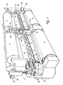
- FIG 1 a multi-system weaving machine is shown in double flat, so-called "back-to-back” construction.
- the machine is set up for the simultaneous production of four fabric webs 1, each of which is wound up into a bale of goods 3 mounted on the machine frame 2.
- the warp threads 5 drawn from the warp beams 4 rotatably mounted on the underside of the machine frame 2 are progressively moved apart in the direction of an arrow 6 by healds 7 movable transversely to the fabric web 1 to form compartments 8, each compartment being traversed by a weft thread carrier 9, the latter Shape in detail, for example, can be seen from Figures 2 and 7.
- the weft thread carriers 9 run one behind the other at a predetermined distance in the manner shown in FIG. 3 on a guideway which is formed on one side by a reed 10 and on the other side by the shafts of the healds 7. They are driven via block-like segments 11, which are longitudinally movably guided on the machine frame 2 and are magnetically coupled to the individual weft thread carriers 9 via permanent magnets 12.
- the segments 11 are fastened to one another at an end on an endless chain 11a and are guided over two vertical, polygonal ' drive rollers 13 which are rotatably mounted in the machine frame, as can be seen from FIG.
- the segments 11 carry, on their underside facing the healds 7, guide tracks (not shown in detail) into which feet formed on the healds of the healds 7 protrude, as is the case in principle in US Pat. No. 3,749,135 and DE-PS 1 963 208 is explained.
- weft flap lamellae 15 project outwards through the warp threads, which serve to strike the respectively inserted weft thread between successive weft thread carriers 9, as indicated at 16 in FIG.
- the machine has 1 e.g. eight weft carriers 9, i.e. eight web systems.
- the insertion of the weft into the weft Carrier 9 takes place in the area between two adjacent fabric webs 1 by means of a weft insertion device 17 assigned to each fabric web, one of which is illustrated in detail in FIGS. 2 to 5 and of which the weaving machine according to FIG. 1 has four pieces. having.
- the weft insertion device 17 shown in the above-mentioned figures has a slide guide 19 mounted on two parallel main supports 18 of the machine frame 2, which consists of three parallel guide rails 19 which are fixedly connected to one another at a predetermined distance and which run parallel to the main rails 18 in two at the ends the main rails 18 fixed cross rails 21 are mounted transversely.
- a slide 22 is fitted, which carries an injector 23, to which a weft thread 24 is fed, which comes from a thread delivery device shown at 25 or 26, which in turn pulls it off from a package 27 or 28.
- the injector 23 shown there in the middle opens in the immediate vicinity of the weft magazine of the weft carrier 9 shown at 29.
- an endless chain 30 which is guided over two deflection rollers 31 which are rotatably mounted on corresponding axes 32 and 33 on one of the main carriers 18.
- One of the pulleys 31 is connected in a rotationally fixed manner to a gearwheel 34 which is in engagement with a gearwheel 37 seated on a shaft 36 mounted in the main carriers 18 and which in turn is connected via the shaft 36 in a rotationally fixed manner to a gearwheel 38 located on the other side of the main carrier 18.
- the gear 38 is in engagement with a rack 39, which consists of individual rack sections, each having the length of one of the segments 11 to which they are attached.
- the chain 30 carries, as can be seen from FIG. 5, four driving teeth 40 in the exemplary embodiment shown, which are arranged at the same distance from one another.
- the upper run of the chain 30 is arranged parallel to the slide guide 19 such that each driver 40 grips the slide piece 22 of the injector 23 standing in the middle (FIG. 3) in a starting position I (FIG. 5) and along the slide guide 19 via a predetermined path in a final position II ver can push.
- the respective driver is brought radially through the right deflection roller 31 in the manner shown in FIG. 5 to the slider 22 in the starting position I and brought into engagement with it, while on the other hand the left deflection roller 31 in the end position II the driver 40 again radially transported away from the slide guide 19 and thereby automatically disengages the slide 22.
- Each of the injectors 23 is connected to a return device which is designed in the form of a spring tension 41 which engages on it and which is anchored at the end in a housing 42.
- a spring 43 is assigned to the spring balancer 41, against which the slide piece 22 which is in the starting position I abuts and which limits its return movement.
- the slide 19 carries two laterally projecting coaxial pins 44, 45 which displaceably in corresponding bores 46, 47 of the main carrier 18 - are guided Lich.
- the one bolt 44 on the outside of the main carrier 18 is under the action of a compression spring 48 which is supported at the end against the bottom of a spring sleeve 49 inserted in the associated main carrier 18 and which slides 1'9, based on FIG. 3, into the right stop position shown presses on the opposite main beam 19.
- the other pin 45 is supported at the end against a double-armed lever 52 which is pivotably mounted on a main support 18 at 51, which lever 52 Carries pressure roller 53, which can come into engagement with a cam track 54 arranged laterally on the respective segment 11 in the region of the rack 39 (FIG. 4).
- a weft carrier 9 comes into the region of a weft insertion device 17, as shown on the right in FIG. 5, one of the injectors 23 (the right one in FIG. 3) is in the starting position I, in which it is located in the path of movement of the drivers 40.
- the injector 23 is taken along by a driver 40 and, synchronized with the movement of the weft thread carrier 29, with a Predetermined speed transferred to the end position I I, in which the driver 40 comes out of engagement with the slider 22.
- the movement of the carriers 40 is coordinated with that of the weft thread carrier 29 in such a way that the injector 23 carried by a carrier 40 is moved with the weft thread carrier 9 on its way between the starting position I and the end position II.
- the speed reduction ratio between the chain 30 and the weft carrier 9 is selected so that during this movement of the slide 22 the injector 23 is displaced relative to the weft carrier 9 by the length of the weft magazine.
- the pressure roller 56 or 56a associated in the weft thread 24 or 24a feeding it is pressed against the thread delivery drum 57, so that this weft thread is inserted into the injector 23, which in turn is located at the mouth of the injector 23 is blown into the air-permeable weft magazine 29.
- the weft thread is cut off at the edge of the fabric by a cutting device, not shown, after it has been partially woven in, held in place and inserted by the continuing weft thread carrier 9 into the compartment of the fabric web 1 has been. Since the spring tension 41 has been tensioned during the movement of the injector 23 with the weft thread holder 9, the slide 22 is immediately returned to the starting position I after the release by the driver 40 from the spring tension 41 returned in which it bears against the stop 43.
- the pitch circle circumference of the gear 38 corresponds exactly to the length of a weaving system (or a multiple thereof).
- the gear 34 is thus driven in a reduction ratio of 2: 1, the distance between the drivers 40 on the chain 30 corresponding to a quarter of the system length in the exemplary embodiment shown. With a system length of 24 cm, a driver moves 12 cm between the two positions I and II.
- the pressure roller 53 runs again from the cam track 54, so that the slide guide 19, based on FIG. 3, moves to the right and the first injector on its slide piece 22 is in turn gripped by the next following driving tooth 40 during the the other injector is now ineffective to the side of the chain 30, as shown on the right in FIG. 3.
- the two injectors 23 are thus alternately used to supply the weft.
- control can also be carried out according to the program, for example by a programming device, so that a weft color change can be carried out by means of the injectors 23.
- the slide guide 19 is then controlled via a rack and a gearwheel by the programming device via a suitable adjusting device, which causes the slide guide 19 to be moved back and forth by the double-armed lever 52.
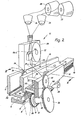
- FIG. 7 an embodiment is illustrated in which four with 23a to 23d designated injectors with their pressure pieces 22a to 22d are each assembled into a register which, like its slide guide 19, is adjustable according to the program transversely to the movement path 62 of the weft thread carrier 9. This makes it possible to supply successive weft thread carriers 9 with four different weft threads.
- the to-and-fro adjustment of the register formed by the injectors 23a to 23d, indicated by an arrow 63, is carried out according to the program via a programming device and an actuating device controlled by it.
- the invention has been described above using a double-flat weaving machine. In principle, it can of course also be used for a circular loom or a loom with a different structure.
- a thread guide element 65 in the form of a fixed pin (FIG. 2) is provided, which is arranged in such a way that the thread travel from the pin 65 holding the weft thread to the injector 23 in the starting position I is longer than to the injector in end position II. It is thereby achieved that after the weft thread has been cut off at the injector 23 standing in the end position II when the injector 23 moves back into the starting position I, the cut weft thread end is drawn into the injector 23 and does not protrude below.
- a tube 70 which may also be designed as a flexible hose and is preferably transparent, placed on it, which ensures lateral guidance of the weft thread 24 or 24a on the way between the thread delivery drum 57 and the respective injector 23, so that the Weft cannot accidentally come out of the injector.
Landscapes
- Engineering & Computer Science (AREA)
- Textile Engineering (AREA)
- Looms (AREA)
Priority Applications (1)
| Application Number | Priority Date | Filing Date | Title |
|---|---|---|---|
| AT81102934T ATE10519T1 (de) | 1980-04-26 | 1981-04-16 | Verfahren und vorrichtung zum pneumatischen eintragen des schussfadens in die schussfadentraeger einer mehrsystemigen webmaschine. |
Applications Claiming Priority (2)
| Application Number | Priority Date | Filing Date | Title |
|---|---|---|---|
| DE3016182A DE3016182C2 (de) | 1980-04-26 | 1980-04-26 | Verfahren und Vorrichtung zum pneumatischen Eintragen des Schußfadens in die Schußfadenträger einer mehrsystemigen Webmaschine |
| DE3016182 | 1980-04-26 |
Publications (2)
| Publication Number | Publication Date |
|---|---|
| EP0039009A1 true EP0039009A1 (fr) | 1981-11-04 |
| EP0039009B1 EP0039009B1 (fr) | 1984-11-28 |
Family
ID=6101052
Family Applications (1)
| Application Number | Title | Priority Date | Filing Date |
|---|---|---|---|
| EP81102934A Expired EP0039009B1 (fr) | 1980-04-26 | 1981-04-16 | Procédé et dispositif pour l'insertion pneumatique d'un fil de trame dans l'inséreur de trame d'un métier à tisser multiple |
Country Status (8)
| Country | Link |
|---|---|
| US (1) | US4410017A (fr) |
| EP (1) | EP0039009B1 (fr) |
| JP (1) | JPH026855B2 (fr) |
| AT (1) | ATE10519T1 (fr) |
| BR (1) | BR8108574A (fr) |
| DE (1) | DE3016182C2 (fr) |
| SU (1) | SU1109056A3 (fr) |
| WO (1) | WO1981003037A1 (fr) |
Cited By (4)
| Publication number | Priority date | Publication date | Assignee | Title |
|---|---|---|---|---|
| EP0297168A1 (fr) * | 1987-06-27 | 1989-01-04 | Lindauer Dornier Gesellschaft M.B.H | Dispositif pour délivrer périodiquement des longueurs mesurées de fil de trame pour un métier à tisser multiple |
| EP0297169A1 (fr) * | 1987-06-27 | 1989-01-04 | Lindauer Dornier Gesellschaft M.B.H | Dispositif pour délivrer périodiquement des longueurs mesurées d'au moins deux fils de trame différents pour l'inséreur de trame d'un métier à tisser multiple |
| EP0297171A1 (fr) * | 1987-05-30 | 1989-01-04 | Lindauer Dornier Gesellschaft M.B.H | Métier à tisser à foule multiple |
| EP0297170A1 (fr) * | 1987-05-30 | 1989-01-04 | Lindauer Dornier Gesellschaft M.B.H | Métier à tisser à foule multiple avec insertion de trame magnétique permanente |
Families Citing this family (6)
| Publication number | Priority date | Publication date | Assignee | Title |
|---|---|---|---|---|
| DE3715742C1 (de) * | 1987-05-12 | 1988-06-01 | Dornier Gmbh Lindauer | Verfahren und Vorrichtung zum Speichern eines Schussfadenstueckes in einem Schussfadenmagazin eines Schussfadentraegers |
| US4850399A (en) * | 1987-06-27 | 1989-07-25 | Lindauer Dorner Gesellschaft M.B.H. | Weaving loom with pneumatic weft thread injection |
| DE3733292C1 (de) * | 1987-10-02 | 1989-01-19 | Dornier Gmbh Lindauer | Webverfahren und Webmaschine zum Herstellen von Frottiergewebe |
| FR3002550B1 (fr) * | 2013-02-22 | 2015-07-17 | Aircelle Sa | Metier a tisser a cadres cote-a-cote, procede de tissage utilisant un tel metier et preformes ainsi tissees. |
| BE1024414B1 (nl) * | 2016-07-04 | 2018-02-12 | Picanol Nv | Opstelling en werkwijze voor het optimaliseren van een weefproces. |
| FR3060614A1 (fr) * | 2016-12-20 | 2018-06-22 | Compagnie Generale Des Etablissements Michelin | Machine a tisser et procede de tissage correspondant |
Citations (4)
| Publication number | Priority date | Publication date | Assignee | Title |
|---|---|---|---|---|
| DE1288025B (fr) * | 1964-12-07 | |||
| DE1287526B (de) * | 1963-03-19 | 1969-01-16 | Oerlikon Buehrle Holding Ag | Verfahren zum Beschicken von Webschuetzen von Webmaschinen, insbesondere von Wellenwebmaschinen, und Vorrichtung zur Durchfuehrung des Verfahrens |
| DE2800639A1 (de) * | 1978-01-07 | 1979-08-02 | Sipra Patent Beteiligung | Wellenfach-webmaschine |
| FR2429276A3 (fr) * | 1978-06-22 | 1980-01-18 | Tsnii Chlopchatobumasch Promy | Dispositif de canetage des organes d'insertion de fil de trame d'un metier a tisser a foule ondulante |
Family Cites Families (5)
| Publication number | Priority date | Publication date | Assignee | Title |
|---|---|---|---|---|
| DE1785416A1 (de) * | 1968-09-20 | 1972-05-04 | Adolf Linka | Verfahren und Vorrichtung zur periodischen Lieferung abgemessener Schussfadenlaengen von einer Spule in einen den Schussfaden in einen kontinuierlich bewegten Schuetzen eintragenden pneumatischen Injektor |
| DE1963208C3 (de) * | 1969-12-17 | 1974-07-04 | Adolf 7451 Hechingensickingen Linka | Wellenwebmaschine |
| US3943976A (en) * | 1971-10-06 | 1976-03-16 | Maquinaria Textil Del Norte De Espana S.A.-Matesa | Continuous insertion weaving machine |
| CH595489A5 (fr) * | 1976-08-20 | 1978-02-15 | Rueti Ag Maschf | |
| US4253498A (en) * | 1979-03-20 | 1981-03-03 | Vinicio Luchi | Travelling wave shedding looms relative to the shuttle loading system |
-
1980
- 1980-04-26 DE DE3016182A patent/DE3016182C2/de not_active Expired
-
1981
- 1981-04-16 AT AT81102934T patent/ATE10519T1/de not_active IP Right Cessation
- 1981-04-16 EP EP81102934A patent/EP0039009B1/fr not_active Expired
- 1981-04-18 JP JP56501530A patent/JPH026855B2/ja not_active Expired - Lifetime
- 1981-04-18 WO PCT/DE1981/000064 patent/WO1981003037A1/fr not_active Ceased
- 1981-04-18 BR BR8108574A patent/BR8108574A/pt unknown
- 1981-04-18 US US06/333,859 patent/US4410017A/en not_active Expired - Fee Related
- 1981-12-17 SU SU813365845A patent/SU1109056A3/ru active
Patent Citations (4)
| Publication number | Priority date | Publication date | Assignee | Title |
|---|---|---|---|---|
| DE1287526B (de) * | 1963-03-19 | 1969-01-16 | Oerlikon Buehrle Holding Ag | Verfahren zum Beschicken von Webschuetzen von Webmaschinen, insbesondere von Wellenwebmaschinen, und Vorrichtung zur Durchfuehrung des Verfahrens |
| DE1288025B (fr) * | 1964-12-07 | |||
| DE2800639A1 (de) * | 1978-01-07 | 1979-08-02 | Sipra Patent Beteiligung | Wellenfach-webmaschine |
| FR2429276A3 (fr) * | 1978-06-22 | 1980-01-18 | Tsnii Chlopchatobumasch Promy | Dispositif de canetage des organes d'insertion de fil de trame d'un metier a tisser a foule ondulante |
Cited By (4)
| Publication number | Priority date | Publication date | Assignee | Title |
|---|---|---|---|---|
| EP0297171A1 (fr) * | 1987-05-30 | 1989-01-04 | Lindauer Dornier Gesellschaft M.B.H | Métier à tisser à foule multiple |
| EP0297170A1 (fr) * | 1987-05-30 | 1989-01-04 | Lindauer Dornier Gesellschaft M.B.H | Métier à tisser à foule multiple avec insertion de trame magnétique permanente |
| EP0297168A1 (fr) * | 1987-06-27 | 1989-01-04 | Lindauer Dornier Gesellschaft M.B.H | Dispositif pour délivrer périodiquement des longueurs mesurées de fil de trame pour un métier à tisser multiple |
| EP0297169A1 (fr) * | 1987-06-27 | 1989-01-04 | Lindauer Dornier Gesellschaft M.B.H | Dispositif pour délivrer périodiquement des longueurs mesurées d'au moins deux fils de trame différents pour l'inséreur de trame d'un métier à tisser multiple |
Also Published As
| Publication number | Publication date |
|---|---|
| JPS57500516A (fr) | 1982-03-25 |
| US4410017A (en) | 1983-10-18 |
| EP0039009B1 (fr) | 1984-11-28 |
| DE3016182C2 (de) | 1983-01-05 |
| BR8108574A (pt) | 1982-04-06 |
| SU1109056A3 (ru) | 1984-08-15 |
| JPH026855B2 (fr) | 1990-02-14 |
| ATE10519T1 (de) | 1984-12-15 |
| WO1981003037A1 (fr) | 1981-10-29 |
| DE3016182A1 (de) | 1981-11-05 |
Similar Documents
| Publication | Publication Date | Title |
|---|---|---|
| DE1685151B2 (de) | Fadenzufuehrvorrichtung fuer die nadeln einer tuftingmaschine | |
| DE69215324T2 (de) | Tetraaxialgewebe und Webstuhl zum Herstellen davon | |
| DE2531734A1 (de) | Fadenfuehrung an maschenbildenden maschinen mit umlaufenden fadenfuehrern | |
| DE3016182C2 (de) | Verfahren und Vorrichtung zum pneumatischen Eintragen des Schußfadens in die Schußfadenträger einer mehrsystemigen Webmaschine | |
| DE2017325B2 (de) | Vorrichtung zur Herstellung eines nicht-gewebten offenmaschigen Netzes | |
| DE2051471A1 (de) | Kettenwirkmaschine | |
| DE2856415A1 (de) | Vorrichtung zur herstellung einer lage paralleler faeden | |
| DE102009022163A1 (de) | Vorrichtung zum Aufbringen einer unidirektionalen Lage und Multiaxialmaschine | |
| DE60116289T3 (de) | Weben von teppichen | |
| DE1535085B1 (de) | Abbindung fuer auf einer Haspel liegende Garnstraenge | |
| DE1926654A1 (de) | Vorrichtung zum Vorbereiten eines Schussfadens | |
| DE19802994C1 (de) | Verfahren und Vorrichtung zum Legen von einander unter verschiedenen Winkeln kreuzenden Diagonalfadenlagen | |
| DE2847520A1 (de) | Fadenvorlegevorrichtung, insbesondere zum vorlegen von kettfaeden fuer das automatische einziehen derselben in litzen und lamellen einer webmaschine | |
| DE4132696C2 (de) | Breithalter und dessen Verwendung bei einer Webmaschine | |
| DE2531705C2 (de) | Strickmaschine | |
| DE3632821C2 (de) | Breithalter | |
| DE3006537A1 (de) | Spulenwickelmaschine | |
| DE2449138A1 (de) | Verfahren und vorrichtung zum foerdern einer vielzahl von materialstraengen entlang einem vorgegebenen foerderweg | |
| DE2724923C3 (de) | Zwillings-Düsen-Webmaschine | |
| DE60116089T2 (de) | Einheit zum Bilden von Tuftinggarnen und Webmaschine | |
| WO2008092802A1 (fr) | Dispositif de positionnement des fils à l'intérieur de la largeur de bande d'une section d'ourdissage et procédé d'ourdissage | |
| DE1535962B1 (de) | Vorrichtung zum Einlesen von Fadenkreuzen in Webketten | |
| DE1535962C (de) | Vorrichtung zum Einlesen von Fadenkreuzen in Webketten | |
| DE3132883C2 (fr) | ||
| EP0022812A1 (fr) | Dispositif de preparation du fil de trame dans un metier sans navette |
Legal Events
| Date | Code | Title | Description |
|---|---|---|---|
| PUAI | Public reference made under article 153(3) epc to a published international application that has entered the european phase |
Free format text: ORIGINAL CODE: 0009012 |
|
| AK | Designated contracting states |
Designated state(s): AT BE CH FR GB IT NL SE |
|
| 17P | Request for examination filed |
Effective date: 19811016 |
|
| ITF | It: translation for a ep patent filed | ||
| GRAA | (expected) grant |
Free format text: ORIGINAL CODE: 0009210 |
|
| AK | Designated contracting states |
Designated state(s): AT BE CH FR GB IT LI NL SE |
|
| PG25 | Lapsed in a contracting state [announced via postgrant information from national office to epo] |
Ref country code: SE Effective date: 19841128 Ref country code: NL Effective date: 19841128 |
|
| REF | Corresponds to: |
Ref document number: 10519 Country of ref document: AT Date of ref document: 19841215 Kind code of ref document: T |
|
| ET | Fr: translation filed | ||
| PG25 | Lapsed in a contracting state [announced via postgrant information from national office to epo] |
Ref country code: AT Effective date: 19850416 |
|
| NLV1 | Nl: lapsed or annulled due to failure to fulfill the requirements of art. 29p and 29m of the patents act | ||
| PLBE | No opposition filed within time limit |
Free format text: ORIGINAL CODE: 0009261 |
|
| STAA | Information on the status of an ep patent application or granted ep patent |
Free format text: STATUS: NO OPPOSITION FILED WITHIN TIME LIMIT |
|
| 26N | No opposition filed | ||
| PGFP | Annual fee paid to national office [announced via postgrant information from national office to epo] |
Ref country code: FR Payment date: 19910121 Year of fee payment: 11 |
|
| PGFP | Annual fee paid to national office [announced via postgrant information from national office to epo] |
Ref country code: GB Payment date: 19910308 Year of fee payment: 11 |
|
| PGFP | Annual fee paid to national office [announced via postgrant information from national office to epo] |
Ref country code: CH Payment date: 19910419 Year of fee payment: 11 |
|
| PGFP | Annual fee paid to national office [announced via postgrant information from national office to epo] |
Ref country code: BE Payment date: 19910425 Year of fee payment: 11 |
|
| ITTA | It: last paid annual fee | ||
| PG25 | Lapsed in a contracting state [announced via postgrant information from national office to epo] |
Ref country code: GB Effective date: 19920416 |
|
| PG25 | Lapsed in a contracting state [announced via postgrant information from national office to epo] |
Ref country code: LI Effective date: 19920430 Ref country code: CH Effective date: 19920430 Ref country code: BE Effective date: 19920430 |
|
| BERE | Be: lapsed |
Owner name: LINKA ADOLF Effective date: 19920430 |
|
| GBPC | Gb: european patent ceased through non-payment of renewal fee | ||
| PG25 | Lapsed in a contracting state [announced via postgrant information from national office to epo] |
Ref country code: FR Effective date: 19921230 |
|
| REG | Reference to a national code |
Ref country code: CH Ref legal event code: PL |
|
| REG | Reference to a national code |
Ref country code: FR Ref legal event code: ST |