EP0039149B1 - Glieder für Schmuckzwecke - Google Patents
Glieder für Schmuckzwecke Download PDFInfo
- Publication number
- EP0039149B1 EP0039149B1 EP81301487A EP81301487A EP0039149B1 EP 0039149 B1 EP0039149 B1 EP 0039149B1 EP 81301487 A EP81301487 A EP 81301487A EP 81301487 A EP81301487 A EP 81301487A EP 0039149 B1 EP0039149 B1 EP 0039149B1
- Authority
- EP
- European Patent Office
- Prior art keywords
- catch
- jewellery
- link
- gap
- arms
- Prior art date
- Legal status (The legal status is an assumption and is not a legal conclusion. Google has not performed a legal analysis and makes no representation as to the accuracy of the status listed.)
- Expired
Links
- 230000014759 maintenance of location Effects 0.000 claims description 3
- 238000004519 manufacturing process Methods 0.000 description 6
- 230000003213 activating effect Effects 0.000 description 3
- 230000008878 coupling Effects 0.000 description 2
- 238000010168 coupling process Methods 0.000 description 2
- 238000005859 coupling reaction Methods 0.000 description 2
- 230000006835 compression Effects 0.000 description 1
- 238000007906 compression Methods 0.000 description 1
- 238000010276 construction Methods 0.000 description 1
- 238000003825 pressing Methods 0.000 description 1
Images

Classifications
-
- A—HUMAN NECESSITIES
- A44—HABERDASHERY; JEWELLERY
- A44C—PERSONAL ADORNMENTS, e.g. JEWELLERY; COINS
- A44C5/00—Bracelets; Wrist-watch straps; Fastenings for bracelets or wrist-watch straps
- A44C5/18—Fasteners for straps, chains or the like
- A44C5/20—Fasteners for straps, chains or the like for open straps, chains or the like
- A44C5/2019—Hooks
- A44C5/2033—Hooks provided with pivoting closure means
-
- F—MECHANICAL ENGINEERING; LIGHTING; HEATING; WEAPONS; BLASTING
- F16—ENGINEERING ELEMENTS AND UNITS; GENERAL MEASURES FOR PRODUCING AND MAINTAINING EFFECTIVE FUNCTIONING OF MACHINES OR INSTALLATIONS; THERMAL INSULATION IN GENERAL
- F16B—DEVICES FOR FASTENING OR SECURING CONSTRUCTIONAL ELEMENTS OR MACHINE PARTS TOGETHER, e.g. NAILS, BOLTS, CIRCLIPS, CLAMPS, CLIPS OR WEDGES; JOINTS OR JOINTING
- F16B45/00—Hooks; Eyes
- F16B45/02—Hooks with pivoting or elastically bending closing member
- F16B45/027—Hooks with pivoting or elastically bending closing member and having position-locking means for the closing member
-
- Y—GENERAL TAGGING OF NEW TECHNOLOGICAL DEVELOPMENTS; GENERAL TAGGING OF CROSS-SECTIONAL TECHNOLOGIES SPANNING OVER SEVERAL SECTIONS OF THE IPC; TECHNICAL SUBJECTS COVERED BY FORMER USPC CROSS-REFERENCE ART COLLECTIONS [XRACs] AND DIGESTS
- Y10—TECHNICAL SUBJECTS COVERED BY FORMER USPC
- Y10S—TECHNICAL SUBJECTS COVERED BY FORMER USPC CROSS-REFERENCE ART COLLECTIONS [XRACs] AND DIGESTS
- Y10S24/00—Buckles, buttons, clasps
- Y10S24/30—Separable-fastener or required component thereof
- Y10S24/31—Separable-fastener or required component thereof with third, detached member completing interlock
- Y10S24/33—Third member includes independently engaged hooks for linking spaced cavities
- Y10S24/34—And movably connected, noninserted gate for closing access throat of hook
-
- Y—GENERAL TAGGING OF NEW TECHNOLOGICAL DEVELOPMENTS; GENERAL TAGGING OF CROSS-SECTIONAL TECHNOLOGIES SPANNING OVER SEVERAL SECTIONS OF THE IPC; TECHNICAL SUBJECTS COVERED BY FORMER USPC CROSS-REFERENCE ART COLLECTIONS [XRACs] AND DIGESTS
- Y10—TECHNICAL SUBJECTS COVERED BY FORMER USPC
- Y10T—TECHNICAL SUBJECTS COVERED BY FORMER US CLASSIFICATION
- Y10T24/00—Buckles, buttons, clasps, etc.
- Y10T24/34—Combined diverse multipart fasteners
- Y10T24/3484—Hook
- Y10T24/3485—Hook and hook
- Y10T24/3489—Hook and hook having securing means
- Y10T24/3493—Pivoted
-
- Y—GENERAL TAGGING OF NEW TECHNOLOGICAL DEVELOPMENTS; GENERAL TAGGING OF CROSS-SECTIONAL TECHNOLOGIES SPANNING OVER SEVERAL SECTIONS OF THE IPC; TECHNICAL SUBJECTS COVERED BY FORMER USPC CROSS-REFERENCE ART COLLECTIONS [XRACs] AND DIGESTS
- Y10—TECHNICAL SUBJECTS COVERED BY FORMER USPC
- Y10T—TECHNICAL SUBJECTS COVERED BY FORMER US CLASSIFICATION
- Y10T24/00—Buckles, buttons, clasps, etc.
- Y10T24/45—Separable-fastener or required component thereof [e.g., projection and cavity to complete interlock]
- Y10T24/45005—Separable-fastener or required component thereof [e.g., projection and cavity to complete interlock] with third detached member completing interlock [e.g., hook type]
- Y10T24/45016—Separable-fastener or required component thereof [e.g., projection and cavity to complete interlock] with third detached member completing interlock [e.g., hook type] for jewelry
Definitions
- This invention relates to a link for jewellery of the type defined in the pre-characterising portion of claim 1.
- the closure most commonly known and used in jewellery is that constituted by a gapped ring having a tubular cross-section, to which is welded a ring which is solidly fixed to one of the terminals of the article of jewellery, and a lock acting along the interior of the tubular body and having an activating pivot protruding outwardly through a notch provided in the gapped ring.
- the lock is urged by a spring to a position in which it closes the gap existing between the ends of said gapped ring. Movement of the activating pivot against the spring opens said gap and allows the ring of the opposite end of the article of jewellery to be engaged with said gapped ring. Release of the activating pivot causes said lock to close said gap and thus retain said opposite end engaged with said ring.
- French Patent Specification No. 1257187 shows a jewellery closure in the form of a gapped ring to which is pivotally engaged a catch movable from a closed position, in which it closes the gap in said member, to an open position, in which said gap is open.
- a generally diagonally arranged member containing a compression spring forms the catch, with the spring forcing a ball against the interior surface of the ring.
- the ball closes the gap in the ring.
- the catch can be pivoted to either side of the gap to allow a link to be engaged with or disengaged from the closure.
- the catch has a peg at its one end which in the closed position of the catch blocks the gap.
- the gap is defined between the free ends of a pair of leaf springs of the ring and the catch can be pivoted to either side of the gap by flexing the spring and thereby opening the gap.
- the object of the invention is thus to provide a link for jewellery which can join together the ends of an article of jewellery in an effective manner, so that the possibility of an end of the article of jewellery becoming detached, due to wear of the link or by accident, is reduced or eliminated.
- a link for jewellery comprising a gapped member of ring-like form on which is engaged a catch movable from a closed position, in which it closes the gap in said member, to an open position, in which said gap is open, characterized in that said gapped member comprises a curved leaf spring, opposite ends of which are formed as open rings from which extend respective flexible curved arms whose free ends are spaced apart to form said gap, said arms being curved in respective directions opposite to the curvature of the leaf spring, said leaf spring being thicker at its mid-point than at its ends and having a notch at said thicker mid-point in which part of said catch is engaged so that, in use, said catch can be pivoted about said notch from said closed position, in which it closes said gap and engages each arm, to said open position engaging one arm, in which a link of an article of jewellery can be engaged with or disengaged from said gapped member.
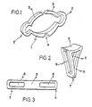
- Figure 1 shows one component of the link of the invention, this component being readily produced in one piece by die stamping which, acting on the strip of rolled material, operates automatically without the need for manual labour and at a rate sufficiently superior to 60 pieces per minute.
- the component of Figure 1 comprises a curved leaf spring 1 which is thicker at its mid-point than at its ends and has a notch 4 cut in its convex surface at said mid-point.
- the ends of the leaf spring 1 are formed into open rings 2 to receive in use, the respective end links 9 of the article of jewellery to be fastened by the link as shown in Figure 4.
- From the open rings 2 extend arms in the form of leaf springs forming flexible arms 3, each of which is curved in the opposite direction to the curvature of the leaf spring 1, so that the concave surfaces of the arms 3 face the concave surface of the spring 1.
- the notch 4 has a flat base and outwardly diverging straight sides and is provided for the reception of part of a pivotable catch, shown in Figure 2.
- the angle formed by the diverging sides of the notch is 90°.
- the catch shown in Figure 2 is produced from a flat elongated plate, shown in Figure 3.
- Rectangular holes 8 are provided in the plate adjacent its opposite ends and the plate is then folded to form a pair of legs 6 and 7 having the holes 8 therein respectively, these legs extending from a central part 5.
- the ends of the legs 6 and 7 are juxtaposed to provide a combined width substantially equal to that of the notch 4, as can be seen from Figure 5.
- the holes 8 form a pair of openings within which the component of Figure 1 is intended to engage, as shown in Figure 4, with the central part 5 covering the gap between the free ends of the arms 3 and the ends of the legs 6 and 7 being fitted in the notch 4.
- Each of the components shown in Figures 1 and 2 can be made from any of the noble materials commonly used in jewellery making, being perfectly integrated with the material constituting the jewellery.
- Another important advantage is that the complete two-piece link is manufactured in a complete automatic manner without the intervention of hand labour and with such a high production rate that it permits the use of other materials, such as those used in imitation jewellery, without causing an increase in the total cost of the product, as is common with the closures existing on the market.
- the two pieces of the link can be produced at equal rates.
- Figures 4 and 5 show how the link is used to connect together respective links 9 at the two ends of a piece of jewellery.
- a convex curved under the surface of the central part 5 engages the free ends of the arms 3.
- Due to the flexibility of the leaf spring 1 and arms 3, a force is developed which causes the catch to lock onto the other link component, with the central part 5 of the catch closing the gap between the free ends of the arms 3 and the ends of the legs 6 and 7 of the catch being engaged centrally within the notch 4.
- the position shown in Figure 4 is thus a rest or closed position of the catch.
- Figure 5 shows how a link 9 at an end of a piece of jewellery can be engaged with or disengaged from one of the semi-rings 2. From its rest position, the catch is pivoted with the ends of its legs 6 and 7 being rocked towards one side of the notch. This moves the central part 5 of the catch fully onto one of the arms 3, thereby releasing the other arm and opening the gap between the free ends of said arms 3. Accordingly a link 9 can be engaged with or removed from the open ring adjacent the released arm, by passing the link 9 through the open gap.
- the catch thus has three locking positions, namely the two pivoted positions allowing access to the respective open rings, and a rest position preventing access to either one.
- the catch can be moved manually between these positions.
- Coupling between both pieces of the link is mechanically carried out using the tools and mechanical means necessary so that a sufficient force is developed which causes the leaf spring 1 and the arms 3 to be so flexibly deformed that they can be inserted through the holes 8, both pieces of the link thus being engaged together so that it is practically impossible to disengage them again manually.
- the leaf spring 1 is thickened at its centre so that the section where the notch 4 is made does not weaken the assembly, maintaining the characteristics of resistance which guarantee the perfect retention and coupling of the end links 9 of the article of jewellery in question.
Landscapes
- Engineering & Computer Science (AREA)
- General Engineering & Computer Science (AREA)
- Mechanical Engineering (AREA)
- Adornments (AREA)
- Pinball Game Machines (AREA)
Claims (6)
Priority Applications (1)
| Application Number | Priority Date | Filing Date | Title |
|---|---|---|---|
| AT81301487T ATE8567T1 (de) | 1980-04-30 | 1981-04-07 | Glieder fuer schmuckzwecke. |
Applications Claiming Priority (2)
| Application Number | Priority Date | Filing Date | Title |
|---|---|---|---|
| ES1980250387U ES250387Y (es) | 1980-04-30 | 1980-04-30 | Conector para joyeria |
| ES250387 | 1980-04-30 |
Publications (2)
| Publication Number | Publication Date |
|---|---|
| EP0039149A1 EP0039149A1 (de) | 1981-11-04 |
| EP0039149B1 true EP0039149B1 (de) | 1984-07-25 |
Family
ID=8408635
Family Applications (1)
| Application Number | Title | Priority Date | Filing Date |
|---|---|---|---|
| EP81301487A Expired EP0039149B1 (de) | 1980-04-30 | 1981-04-07 | Glieder für Schmuckzwecke |
Country Status (6)
| Country | Link |
|---|---|
| US (1) | US4382319A (de) |
| EP (1) | EP0039149B1 (de) |
| JP (1) | JPS6012042B2 (de) |
| AT (1) | ATE8567T1 (de) |
| ES (1) | ES250387Y (de) |
| MX (1) | MX152155A (de) |
Families Citing this family (7)
| Publication number | Priority date | Publication date | Assignee | Title |
|---|---|---|---|---|
| JPS648162U (de) * | 1987-07-02 | 1989-01-18 | ||
| DE19714754C2 (de) * | 1996-11-12 | 2000-06-29 | Hartung Hans Joachim | Verschlußeinrichtung für ein Schmuckstück, insbesondere für eine Kette oder ein Collier |
| US6308385B1 (en) * | 1999-11-29 | 2001-10-30 | Peter Franklin Ball | Jewelry clasp |
| US7350376B2 (en) * | 2003-08-22 | 2008-04-01 | Denise Couling | Jewelry clasp |
| FR3064455B1 (fr) * | 2017-03-30 | 2019-06-07 | Antonin Helea | Systeme de connexion d'au moins deux elements d'un article de bijouterie |
| US11864635B2 (en) * | 2021-10-18 | 2024-01-09 | Orbitkey Projects Pty Ltd | Securement device |
| USD1050713S1 (en) | 2022-08-30 | 2024-11-12 | Orbitkey Group Pty Ltd | Keyring |
Family Cites Families (14)
| Publication number | Priority date | Publication date | Assignee | Title |
|---|---|---|---|---|
| US603576A (en) * | 1898-05-03 | Combined buckle and snap-hook | ||
| AT46982B (de) | 1909-09-21 | 1911-03-27 | Florian Tentschert | Gitter für Fensterrahmen oder dgl. |
| US1094568A (en) * | 1912-12-21 | 1914-04-28 | Bastian Brothers Company | Key-ring. |
| US1235854A (en) * | 1917-02-23 | 1917-08-07 | Charles H Stapf | Detachable link for fish-hook leaders. |
| US1390980A (en) * | 1918-12-28 | 1921-09-20 | Steel Products Co | Connecting device |
| GB190828A (en) * | 1921-10-05 | 1923-01-04 | Andrew Kirk Todd | Improvements in fastening devices for watch wristlet and other straps and for other articles |
| US1841423A (en) * | 1931-07-29 | 1932-01-19 | William A H Wells | Clasp |
| FR1257187A (fr) * | 1960-02-18 | 1961-03-31 | Dispositif de fermeture pour anneaux brisés, manilles, porte-clés et autres applications analogues | |
| FR1371938A (fr) * | 1963-07-30 | 1964-09-11 | Zuccolo Rochet & Cie | Bracelet pour montre |
| US3234616A (en) * | 1965-02-16 | 1966-02-15 | Edward F Wantland | Ring fasteners |
| BE724314A (de) * | 1967-11-28 | 1969-05-02 | ||
| US3905069A (en) * | 1974-08-05 | 1975-09-16 | Zem Of Wales Limited | Securing devices for use in jewellery |
| US3950828A (en) * | 1975-02-03 | 1976-04-20 | American Gold Chain Company, Inc. | Chain clasp |
| AT371610B (de) * | 1982-02-09 | 1983-07-11 | Poulicek Susanne | Winker fuer einspurige fahrzeuge |
-
1980
- 1980-04-30 ES ES1980250387U patent/ES250387Y/es not_active Expired
-
1981
- 1981-02-05 US US06/231,624 patent/US4382319A/en not_active Expired - Fee Related
- 1981-04-07 AT AT81301487T patent/ATE8567T1/de not_active IP Right Cessation
- 1981-04-07 EP EP81301487A patent/EP0039149B1/de not_active Expired
- 1981-04-27 JP JP56065134A patent/JPS6012042B2/ja not_active Expired
- 1981-04-29 MX MX187083A patent/MX152155A/es unknown
Also Published As
| Publication number | Publication date |
|---|---|
| ES250387Y (es) | 1981-04-16 |
| ES250387U (es) | 1980-11-16 |
| US4382319A (en) | 1983-05-10 |
| JPS6012042B2 (ja) | 1985-03-29 |
| MX152155A (es) | 1985-05-31 |
| JPS56161001A (en) | 1981-12-11 |
| ATE8567T1 (de) | 1984-08-15 |
| EP0039149A1 (de) | 1981-11-04 |
Similar Documents
| Publication | Publication Date | Title |
|---|---|---|
| US4277864A (en) | Spring operated clip | |
| CA1158844A (en) | Buckles | |
| US4220017A (en) | Convertible finger ring | |
| US4005510A (en) | Plastic clip | |
| EP0682484B1 (de) | Öffenbarer ring mit zwischenelement | |
| US6308385B1 (en) | Jewelry clasp | |
| EP0039149B1 (de) | Glieder für Schmuckzwecke | |
| US6311373B1 (en) | Intermediate clasp for band type ornaments | |
| CN1768637B (zh) | 表带扣 | |
| US3404440A (en) | Jewelry attachment | |
| US5579559A (en) | Bracelet clasp of the unfolding buckle type | |
| US5870803A (en) | Double-locking clasp for watch band | |
| US7210313B1 (en) | Release mechanism for a bangle | |
| US5076073A (en) | Jewel with interchangeable component elements | |
| US4562704A (en) | Jewelry clasp | |
| US4141118A (en) | Hook and ring clasp | |
| KR102077916B1 (ko) | 초기 걸림기능이 내재된 장신구의 연결구조 | |
| US4593440A (en) | Clasp with positive latch mechanism | |
| US3735455A (en) | Slip-through buckle | |
| US2784475A (en) | Jewelry clasp | |
| US4840044A (en) | Articulated wristlet | |
| US4315352A (en) | Locking device for a bracelet or necklace | |
| US3685106A (en) | Buckle | |
| US4287641A (en) | Self-closing hinge | |
| US2637089A (en) | Spring hook clasp |
Legal Events
| Date | Code | Title | Description |
|---|---|---|---|
| PUAI | Public reference made under article 153(3) epc to a published international application that has entered the european phase |
Free format text: ORIGINAL CODE: 0009012 |
|
| AK | Designated contracting states |
Designated state(s): AT BE CH DE FR GB IT LU NL SE |
|
| 17P | Request for examination filed |
Effective date: 19811117 |
|
| ITF | It: translation for a ep patent filed | ||
| GRAA | (expected) grant |
Free format text: ORIGINAL CODE: 0009210 |
|
| AK | Designated contracting states |
Designated state(s): AT BE CH DE FR GB IT LI LU NL SE |
|
| PG25 | Lapsed in a contracting state [announced via postgrant information from national office to epo] |
Ref country code: SE Effective date: 19840725 Ref country code: NL Effective date: 19840725 Ref country code: LI Effective date: 19840725 Ref country code: CH Effective date: 19840725 Ref country code: BE Effective date: 19840725 Ref country code: AT Effective date: 19840725 |
|
| REF | Corresponds to: |
Ref document number: 8567 Country of ref document: AT Date of ref document: 19840815 Kind code of ref document: T |
|
| REF | Corresponds to: |
Ref document number: 3164988 Country of ref document: DE Date of ref document: 19840830 |
|
| ET | Fr: translation filed | ||
| REG | Reference to a national code |
Ref country code: CH Ref legal event code: PL |
|
| NLV1 | Nl: lapsed or annulled due to failure to fulfill the requirements of art. 29p and 29m of the patents act | ||
| PG25 | Lapsed in a contracting state [announced via postgrant information from national office to epo] |
Ref country code: LU Free format text: LAPSE BECAUSE OF NON-PAYMENT OF DUE FEES Effective date: 19850430 |
|
| PLBE | No opposition filed within time limit |
Free format text: ORIGINAL CODE: 0009261 |
|
| STAA | Information on the status of an ep patent application or granted ep patent |
Free format text: STATUS: NO OPPOSITION FILED WITHIN TIME LIMIT |
|
| 26N | No opposition filed | ||
| GBPC | Gb: european patent ceased through non-payment of renewal fee | ||
| PG25 | Lapsed in a contracting state [announced via postgrant information from national office to epo] |
Ref country code: FR Free format text: LAPSE BECAUSE OF NON-PAYMENT OF DUE FEES Effective date: 19871230 |
|
| PG25 | Lapsed in a contracting state [announced via postgrant information from national office to epo] |
Ref country code: DE Effective date: 19880101 |
|
| REG | Reference to a national code |
Ref country code: FR Ref legal event code: ST |
|
| PG25 | Lapsed in a contracting state [announced via postgrant information from national office to epo] |
Ref country code: GB Effective date: 19881118 |