EP0039281A2 - Zwischenschaltungsadapter für statische Umformeranordnung - Google Patents
Zwischenschaltungsadapter für statische Umformeranordnung Download PDFInfo
- Publication number
- EP0039281A2 EP0039281A2 EP81400637A EP81400637A EP0039281A2 EP 0039281 A2 EP0039281 A2 EP 0039281A2 EP 81400637 A EP81400637 A EP 81400637A EP 81400637 A EP81400637 A EP 81400637A EP 0039281 A2 EP0039281 A2 EP 0039281A2
- Authority
- EP
- European Patent Office
- Prior art keywords
- current
- intermediate circuit
- thyristor
- thyristors
- output
- Prior art date
- Legal status (The legal status is an assumption and is not a legal conclusion. Google has not performed a legal analysis and makes no representation as to the accuracy of the status listed.)
- Granted
Links
Images
Classifications
-
- H—ELECTRICITY
- H02—GENERATION; CONVERSION OR DISTRIBUTION OF ELECTRIC POWER
- H02P—CONTROL OR REGULATION OF ELECTRIC MOTORS, ELECTRIC GENERATORS OR DYNAMO-ELECTRIC CONVERTERS; CONTROLLING TRANSFORMERS, REACTORS OR CHOKE COILS
- H02P27/00—Arrangements or methods for the control of AC motors characterised by the kind of supply voltage
- H02P27/04—Arrangements or methods for the control of AC motors characterised by the kind of supply voltage using variable-frequency supply voltage, e.g. inverter or converter supply voltage
- H02P27/06—Arrangements or methods for the control of AC motors characterised by the kind of supply voltage using variable-frequency supply voltage, e.g. inverter or converter supply voltage using DC to AC converters or inverters
-
- H—ELECTRICITY
- H02—GENERATION; CONVERSION OR DISTRIBUTION OF ELECTRIC POWER
- H02M—APPARATUS FOR CONVERSION BETWEEN AC AND AC, BETWEEN AC AND DC, OR BETWEEN DC AND DC, AND FOR USE WITH MAINS OR SIMILAR POWER SUPPLY SYSTEMS; CONVERSION OF DC OR AC INPUT POWER INTO SURGE OUTPUT POWER; CONTROL OR REGULATION THEREOF
- H02M5/00—Conversion of AC power input into AC power output, e.g. for change of voltage, for change of frequency, for change of number of phases
- H02M5/40—Conversion of AC power input into AC power output, e.g. for change of voltage, for change of frequency, for change of number of phases with intermediate conversion into DC
- H02M5/42—Conversion of AC power input into AC power output, e.g. for change of voltage, for change of frequency, for change of number of phases with intermediate conversion into DC by static converters
- H02M5/44—Conversion of AC power input into AC power output, e.g. for change of voltage, for change of frequency, for change of number of phases with intermediate conversion into DC by static converters using discharge tubes or semiconductor devices to convert the intermediate DC into AC
- H02M5/443—Conversion of AC power input into AC power output, e.g. for change of voltage, for change of frequency, for change of number of phases with intermediate conversion into DC by static converters using discharge tubes or semiconductor devices to convert the intermediate DC into AC using devices of a thyratron or thyristor type requiring extinguishing means
- H02M5/45—Conversion of AC power input into AC power output, e.g. for change of voltage, for change of frequency, for change of number of phases with intermediate conversion into DC by static converters using discharge tubes or semiconductor devices to convert the intermediate DC into AC using devices of a thyratron or thyristor type requiring extinguishing means using semiconductor devices only
- H02M5/4505—Conversion of AC power input into AC power output, e.g. for change of voltage, for change of frequency, for change of number of phases with intermediate conversion into DC by static converters using discharge tubes or semiconductor devices to convert the intermediate DC into AC using devices of a thyratron or thyristor type requiring extinguishing means using semiconductor devices only having a rectifier with controlled elements
-
- H—ELECTRICITY
- H02—GENERATION; CONVERSION OR DISTRIBUTION OF ELECTRIC POWER
- H02P—CONTROL OR REGULATION OF ELECTRIC MOTORS, ELECTRIC GENERATORS OR DYNAMO-ELECTRIC CONVERTERS; CONTROLLING TRANSFORMERS, REACTORS OR CHOKE COILS
- H02P2201/00—Indexing scheme relating to controlling arrangements characterised by the converter used
- H02P2201/03—AC-DC converter stage controlled to provide a defined DC link voltage
Definitions
- the present invention relates to the transformation of an input power into alternating or direct current into an output power into alternating current with intermediate transformation into direct current by means of static converters, and, more particularly, an adapter arranged in the intermediate circuit. so as to avoid the formation of harmonics at variable frequencies of the current in the input power supply network when switching the thyristors of the static converters
- the object of the present invention is to modify the shape of the current waves generated on the supply line, so as to reduce the disturbances in this line while allowing a significant reduction in the rate of harmonics at fixed frequency.
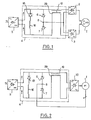
- the intermediate circuit 4 includes two inductors 19.29 with a high coupling factor by mutual inductance, the main role of which is to ensure the smoothing of the current applied to the motors while allowing instantaneous transfer of the current from an armature winding of the motor 1 to the other during the switching of the thyristors of the inverters at start-up or at low motor speed.
- the branch formed by the inductor 16 and the thyristor 18 will play a freewheeling role, but its intervention will be delayed due to the inductor 16.
- This delay will be determined by the value of the instantaneous voltage and the value of the inductance.
- the inductance 16 is chosen so that its value is equal to the sum of the motor leakage inductance and the mutual inductance 19-29. In these conditions, the delay will be the same as when there is a switching to be carried out in inverters 2 or 3.
- the freewheel is therefore established identically and the current disappears in the power source with the same delay.
- the thyristors of the rectifier 5 can be started.
- the voltage then becomes positive again, the current disappears from the freewheel constituted by the inductance 16 and the thyristor 18 with a delay also determined by the instantaneous voltage and the value of the inductance 16. It then reappears in the line with this same delay.
Landscapes
- Engineering & Computer Science (AREA)
- Power Engineering (AREA)
- Inverter Devices (AREA)
- Control Of Ac Motors In General (AREA)
- Electric Propulsion And Braking For Vehicles (AREA)
Applications Claiming Priority (2)
| Application Number | Priority Date | Filing Date | Title |
|---|---|---|---|
| FR8009187 | 1980-04-24 | ||
| FR8009187A FR2481536A1 (fr) | 1980-04-24 | 1980-04-24 | Adaptateur pour circuit intermediaire d'un ensemble de convertisseurs statiques |
Publications (3)
| Publication Number | Publication Date |
|---|---|
| EP0039281A2 true EP0039281A2 (de) | 1981-11-04 |
| EP0039281A3 EP0039281A3 (en) | 1981-11-18 |
| EP0039281B1 EP0039281B1 (de) | 1984-11-14 |
Family
ID=9241301
Family Applications (1)
| Application Number | Title | Priority Date | Filing Date |
|---|---|---|---|
| EP81400637A Expired EP0039281B1 (de) | 1980-04-24 | 1981-04-22 | Zwischenschaltungsadapter für statische Umformeranordnung |
Country Status (8)
| Country | Link |
|---|---|
| US (1) | US4405888A (de) |
| EP (1) | EP0039281B1 (de) |
| AU (1) | AU545026B2 (de) |
| CA (1) | CA1167914A (de) |
| DE (1) | DE3167152D1 (de) |
| FR (1) | FR2481536A1 (de) |
| MX (1) | MX154955A (de) |
| ZA (1) | ZA812709B (de) |
Cited By (2)
| Publication number | Priority date | Publication date | Assignee | Title |
|---|---|---|---|---|
| FR2534424A1 (fr) * | 1982-10-07 | 1984-04-13 | Jeumont Schneider | Circuit de commande d'un moteur synchrone a deux enroulements induits |
| EP0323173A3 (en) * | 1987-12-28 | 1990-08-22 | Kabushiki Kaisha Toshiba | Power converter device |
Families Citing this family (2)
| Publication number | Priority date | Publication date | Assignee | Title |
|---|---|---|---|---|
| US5548165A (en) * | 1994-07-18 | 1996-08-20 | Regents Of The University Of Minnesota | Hybrid filter for reducing distortion in a power system |
| DE502005003999D1 (de) * | 2005-06-08 | 2008-06-19 | Abb Schweiz Ag | Verfahren zum Betrieb einer rotierenden elektrischen Maschine sowie Vorrichtung zur Durchführung des Verfahrens |
Family Cites Families (6)
| Publication number | Priority date | Publication date | Assignee | Title |
|---|---|---|---|---|
| US3825814A (en) * | 1973-05-29 | 1974-07-23 | Westinghouse Electric Corp | Active filter for the input harmonic current of static power converters |
| JPS6035915B2 (ja) * | 1975-08-29 | 1985-08-17 | 富士電機株式会社 | 電動機駆動用インバ−タの非常運転方法 |
| JPS54735A (en) * | 1977-06-02 | 1979-01-06 | Toshiba Corp | Inverter unit |
| JPS543226A (en) * | 1977-06-08 | 1979-01-11 | Mitsubishi Electric Corp | Ac feeder |
| JPS5426420A (en) * | 1977-07-28 | 1979-02-28 | Kin Tokai | Accac converter circuit |
| US4241395A (en) * | 1978-11-08 | 1980-12-23 | Westinghouse Electric Corp. | Non-dissipative DC active filter and transformer |
-
1980
- 1980-04-24 FR FR8009187A patent/FR2481536A1/fr active Granted
-
1981
- 1981-04-21 US US06/256,115 patent/US4405888A/en not_active Expired - Lifetime
- 1981-04-22 AU AU69735/81A patent/AU545026B2/en not_active Ceased
- 1981-04-22 EP EP81400637A patent/EP0039281B1/de not_active Expired
- 1981-04-22 DE DE8181400637T patent/DE3167152D1/de not_active Expired
- 1981-04-23 MX MX186974A patent/MX154955A/es unknown
- 1981-04-24 ZA ZA00812709A patent/ZA812709B/xx unknown
- 1981-04-24 CA CA000376190A patent/CA1167914A/fr not_active Expired
Cited By (4)
| Publication number | Priority date | Publication date | Assignee | Title |
|---|---|---|---|---|
| FR2534424A1 (fr) * | 1982-10-07 | 1984-04-13 | Jeumont Schneider | Circuit de commande d'un moteur synchrone a deux enroulements induits |
| EP0107539A1 (de) * | 1982-10-07 | 1984-05-02 | JEUMONT-SCHNEIDER Société anonyme dite: | Steuerschaltung für einen Synchronmotor mit zwei Ankerwicklungen |
| US4518908A (en) * | 1982-10-07 | 1985-05-21 | Jeumont-Schneider Corporation | Control circuit of a synchronous motor with two induction windings |
| EP0323173A3 (en) * | 1987-12-28 | 1990-08-22 | Kabushiki Kaisha Toshiba | Power converter device |
Also Published As
| Publication number | Publication date |
|---|---|
| FR2481536A1 (fr) | 1981-10-30 |
| AU6973581A (en) | 1981-10-29 |
| ZA812709B (en) | 1982-04-28 |
| EP0039281B1 (de) | 1984-11-14 |
| MX154955A (es) | 1988-01-14 |
| AU545026B2 (en) | 1985-06-27 |
| DE3167152D1 (en) | 1984-12-20 |
| EP0039281A3 (en) | 1981-11-18 |
| US4405888A (en) | 1983-09-20 |
| FR2481536B1 (de) | 1984-05-25 |
| CA1167914A (fr) | 1984-05-22 |
Similar Documents
| Publication | Publication Date | Title |
|---|---|---|
| FR2631756A1 (fr) | Alimentation electrique a commande par modulation d'impulsions en largeur, pouvant eliminer des potentiels de terre les composantes de signal de frequence de modulation | |
| FR2486328A1 (fr) | Dispositif perfectionne d'economie d'energie pour moteurs a induction | |
| EP0289373B1 (de) | Pulsbreitenmodulationsumwandler | |
| EP0788678B1 (de) | Verfahren und schaltungsanordnung zur leistungssteuerung einer last durch ein phasensteuerungssystem | |
| EP0147280B1 (de) | Speiseverfahren und -vorrichtung für eine Last, insbesondere einen Gleichstrommotor für Doppelspannungseisenbahnlokomotiven | |
| EP0039281B1 (de) | Zwischenschaltungsadapter für statische Umformeranordnung | |
| EP0107539B1 (de) | Steuerschaltung für einen Synchronmotor mit zwei Ankerwicklungen | |
| FR2867915A1 (fr) | Dispositif et procede de commande d'un convertisseur et convertisseur et installation electrique comportant un tel dispositif | |
| EP0031780B1 (de) | Vorrichtung zur Rückgewinnung der Energie eines Wechselrichters | |
| FR2584058A1 (fr) | Dispositif et procede pour la commande de la vitesse d'entrainement d'un escalier mecanique. | |
| FR2479600A1 (fr) | Dispositif d'adaptation pour circuit intermediaire d'un ensemble convertisseur alternatif-alternatif | |
| EP0370896A1 (de) | Leistungs-Schalteinrichtung, insbesondere für Umrichter | |
| FR2668665A1 (fr) | Convertisseur de tension a decoupage, a commutation perfectionnee. | |
| EP0087115B1 (de) | Versorgungs- und Steuerungseinheit einer mit verstellbarer Geschwindigkeit laufenden Synchronmaschine | |
| FR2674382A1 (fr) | Dispositif de regulation de tension de sortie pour alternateur. | |
| EP0507663B1 (de) | Verfahren und Vorrichtung zum Dämpfen des Funkstörungseffektes auf Leitern im mehrphasigen Wechselstromnetz | |
| FR2472297A1 (fr) | Dispositif d'alimentation du type convertisseur | |
| EP0670628B1 (de) | Stromversorgungsvorrichtung für einen Wechselstrommotor | |
| FR2468248A1 (fr) | Circuit de supression de bruit pour moteur electrique commande par thyristors | |
| FR2888956A1 (fr) | Systeme d'attenuation de dephasages et d'harmoniques entre au moins une source d'energie et au moins un moteur electrique sans balais. | |
| EP0122227A1 (de) | Regelbare Spannungsversorgungsschaltung | |
| FR2497025A1 (fr) | Dispositif economiseur d'energie pour moteurs a induction polyphases | |
| FR2472875A1 (fr) | Circuit de commande de deux moteurs synchrones | |
| FR2682829A1 (fr) | Dispositif perfectionne d'alimentation en energie electrique d'un ozoneur. | |
| EP0165843A1 (de) | Umkehrbarer Stromumrichter und unterbrechungsfreie Stromversorgung mit demselben |
Legal Events
| Date | Code | Title | Description |
|---|---|---|---|
| PUAI | Public reference made under article 153(3) epc to a published international application that has entered the european phase |
Free format text: ORIGINAL CODE: 0009012 |
|
| PUAL | Search report despatched |
Free format text: ORIGINAL CODE: 0009013 |
|
| AK | Designated contracting states |
Designated state(s): CH DE GB IT |
|
| AK | Designated contracting states |
Designated state(s): CH DE GB IT |
|
| ITCL | It: translation for ep claims filed |
Representative=s name: BARZANO' E ZANARDO ROMA S.P.A. |
|
| 17P | Request for examination filed |
Effective date: 19820228 |
|
| R17P | Request for examination filed (corrected) |
Effective date: 19820128 |
|
| DET | De: translation of patent claims | ||
| ITF | It: translation for a ep patent filed | ||
| GRAA | (expected) grant |
Free format text: ORIGINAL CODE: 0009210 |
|
| AK | Designated contracting states |
Designated state(s): CH DE GB IT LI |
|
| REF | Corresponds to: |
Ref document number: 3167152 Country of ref document: DE Date of ref document: 19841220 |
|
| PLBE | No opposition filed within time limit |
Free format text: ORIGINAL CODE: 0009261 |
|
| STAA | Information on the status of an ep patent application or granted ep patent |
Free format text: STATUS: NO OPPOSITION FILED WITHIN TIME LIMIT |
|
| 26N | No opposition filed | ||
| ITTA | It: last paid annual fee | ||
| PGFP | Annual fee paid to national office [announced via postgrant information from national office to epo] |
Ref country code: GB Payment date: 19960212 Year of fee payment: 16 Ref country code: DE Payment date: 19960212 Year of fee payment: 16 |
|
| PGFP | Annual fee paid to national office [announced via postgrant information from national office to epo] |
Ref country code: CH Payment date: 19960222 Year of fee payment: 16 |
|
| PG25 | Lapsed in a contracting state [announced via postgrant information from national office to epo] |
Ref country code: GB Effective date: 19970422 |
|
| PG25 | Lapsed in a contracting state [announced via postgrant information from national office to epo] |
Ref country code: LI Free format text: LAPSE BECAUSE OF NON-PAYMENT OF DUE FEES Effective date: 19970430 Ref country code: CH Free format text: LAPSE BECAUSE OF NON-PAYMENT OF DUE FEES Effective date: 19970430 |
|
| GBPC | Gb: european patent ceased through non-payment of renewal fee |
Effective date: 19970422 |
|
| REG | Reference to a national code |
Ref country code: CH Ref legal event code: PL |
|
| PG25 | Lapsed in a contracting state [announced via postgrant information from national office to epo] |
Ref country code: DE Free format text: LAPSE BECAUSE OF NON-PAYMENT OF DUE FEES Effective date: 19980101 |