EP0107539A1 - Steuerschaltung für einen Synchronmotor mit zwei Ankerwicklungen - Google Patents
Steuerschaltung für einen Synchronmotor mit zwei Ankerwicklungen Download PDFInfo
- Publication number
- EP0107539A1 EP0107539A1 EP83401851A EP83401851A EP0107539A1 EP 0107539 A1 EP0107539 A1 EP 0107539A1 EP 83401851 A EP83401851 A EP 83401851A EP 83401851 A EP83401851 A EP 83401851A EP 0107539 A1 EP0107539 A1 EP 0107539A1
- Authority
- EP
- European Patent Office
- Prior art keywords
- thyristors
- inverters
- terminals
- input terminals
- circuit
- Prior art date
- Legal status (The legal status is an assumption and is not a legal conclusion. Google has not performed a legal analysis and makes no representation as to the accuracy of the status listed.)
- Granted
Links
- 238000004804 winding Methods 0.000 title claims abstract description 25
- 230000001360 synchronised effect Effects 0.000 title claims abstract description 12
- 230000008878 coupling Effects 0.000 claims abstract description 4
- 238000010168 coupling process Methods 0.000 claims abstract description 4
- 238000005859 coupling reaction Methods 0.000 claims abstract description 4
- 239000003990 capacitor Substances 0.000 claims description 33
- 238000000034 method Methods 0.000 claims description 3
- 230000001629 suppression Effects 0.000 claims 1
- 230000006698 induction Effects 0.000 abstract 2
- 230000000694 effects Effects 0.000 description 9
- 235000021183 entrée Nutrition 0.000 description 4
- 230000007423 decrease Effects 0.000 description 3
- 239000004020 conductor Substances 0.000 description 1
- 238000010586 diagram Methods 0.000 description 1
- 238000007599 discharging Methods 0.000 description 1
- 238000009499 grossing Methods 0.000 description 1
- 230000001788 irregular Effects 0.000 description 1
- 230000004048 modification Effects 0.000 description 1
- 238000012986 modification Methods 0.000 description 1
- 230000007935 neutral effect Effects 0.000 description 1
- 230000037452 priming Effects 0.000 description 1
- 239000004065 semiconductor Substances 0.000 description 1
- 230000003068 static effect Effects 0.000 description 1
- 238000011144 upstream manufacturing Methods 0.000 description 1
Images

Classifications
-
- H—ELECTRICITY
- H02—GENERATION; CONVERSION OR DISTRIBUTION OF ELECTRIC POWER
- H02P—CONTROL OR REGULATION OF ELECTRIC MOTORS, ELECTRIC GENERATORS OR DYNAMO-ELECTRIC CONVERTERS; CONTROLLING TRANSFORMERS, REACTORS OR CHOKE COILS
- H02P1/00—Arrangements for starting electric motors or dynamo-electric converters
- H02P1/16—Arrangements for starting electric motors or dynamo-electric converters for starting dynamo-electric motors or dynamo-electric converters
- H02P1/46—Arrangements for starting electric motors or dynamo-electric converters for starting dynamo-electric motors or dynamo-electric converters for starting an individual synchronous motor
-
- H—ELECTRICITY
- H02—GENERATION; CONVERSION OR DISTRIBUTION OF ELECTRIC POWER
- H02M—APPARATUS FOR CONVERSION BETWEEN AC AND AC, BETWEEN AC AND DC, OR BETWEEN DC AND DC, AND FOR USE WITH MAINS OR SIMILAR POWER SUPPLY SYSTEMS; CONVERSION OF DC OR AC INPUT POWER INTO SURGE OUTPUT POWER; CONTROL OR REGULATION THEREOF
- H02M5/00—Conversion of AC power input into AC power output, e.g. for change of voltage, for change of frequency, for change of number of phases
- H02M5/40—Conversion of AC power input into AC power output, e.g. for change of voltage, for change of frequency, for change of number of phases with intermediate conversion into DC
- H02M5/42—Conversion of AC power input into AC power output, e.g. for change of voltage, for change of frequency, for change of number of phases with intermediate conversion into DC by static converters
- H02M5/44—Conversion of AC power input into AC power output, e.g. for change of voltage, for change of frequency, for change of number of phases with intermediate conversion into DC by static converters using discharge tubes or semiconductor devices to convert the intermediate DC into AC
- H02M5/443—Conversion of AC power input into AC power output, e.g. for change of voltage, for change of frequency, for change of number of phases with intermediate conversion into DC by static converters using discharge tubes or semiconductor devices to convert the intermediate DC into AC using devices of a thyratron or thyristor type requiring extinguishing means
- H02M5/45—Conversion of AC power input into AC power output, e.g. for change of voltage, for change of frequency, for change of number of phases with intermediate conversion into DC by static converters using discharge tubes or semiconductor devices to convert the intermediate DC into AC using devices of a thyratron or thyristor type requiring extinguishing means using semiconductor devices only
- H02M5/4505—Conversion of AC power input into AC power output, e.g. for change of voltage, for change of frequency, for change of number of phases with intermediate conversion into DC by static converters using discharge tubes or semiconductor devices to convert the intermediate DC into AC using devices of a thyratron or thyristor type requiring extinguishing means using semiconductor devices only having a rectifier with controlled elements
-
- H—ELECTRICITY
- H02—GENERATION; CONVERSION OR DISTRIBUTION OF ELECTRIC POWER
- H02P—CONTROL OR REGULATION OF ELECTRIC MOTORS, ELECTRIC GENERATORS OR DYNAMO-ELECTRIC CONVERTERS; CONTROLLING TRANSFORMERS, REACTORS OR CHOKE COILS
- H02P25/00—Arrangements or methods for the control of AC motors characterised by the kind of AC motor or by structural details
- H02P25/02—Arrangements or methods for the control of AC motors characterised by the kind of AC motor or by structural details characterised by the kind of motor
- H02P25/022—Synchronous motors
- H02P25/024—Synchronous motors controlled by supply frequency
Definitions
- the present invention relates to a control circuit of a synchronous motor with two induced windings, allowing in particular a regular starting of the motor.
- French patent 2,452,200 describes a control circuit making it possible to eliminate these irregularities in the motor torque at start-up, by compensating for the reduction in motor torque resulting from the cancellation of the current in a winding during the switching of the sets of thyristors. by an increase in the current applied to the other winding, so that at low speeds, and in particular when the engine is started, the sum of the instantaneous currents flowing in all the windings of the motor is constant.
- the circuit described is not suitable if the device for the power supply includes a chopper or a mixed bridge rectifier.
- the object of the invention is to obviate this drawback and to ensure starting without irregularity of the engine torque.
- the subject of the invention is therefore a method and a device for switching the thyristors of two inverters supplying a synchronous motor with two windings induced when the engine starts and at low speed.
- the sup pressure of the current flowing in the thyristors to be switched from each inverter takes place during a freewheeling phase during which the branch placed at the output of the supply device is conductive.
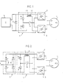
- the two induced windings of the synchronous motor 1 to be controlled are respectively connected to the output terminals of two inverters 2 and 3 connected in series and whose input terminals are connected to an intermediate circuit 4 connected to the terminals of an electrical supply device 5, the output terminals of which are connected by a diode 6.
- a central unit not shown in the figure ensures the priming of the various thyristors of the circuit.
- the intermediate circuit 4 includes two inductors 12 and 13 with a high coupling factor by mutual inductance whose main role is to ensure the transfer of current from an induced winding of the motor 1 to the other when starting or at low engine speed 1, it being understood that as soon as the engine speed
- the two inductors 12 and 13 above which also play the role of smoothing inductors, can be produced using a single inductor with outgoing mid-point, as shown in FIG. 4.
- the supply device delivers a interrupted direct current which can for example be supplied by a mixed bridge rectifier equipment if it is connected to an alternating power source, or by a chopper if it is connected to a continuous power source.
- the circuit is supplied by way of example by a rectifier 7, known as a mixed bridge which allows a much less current to be used than a so-called full bridge rectifier at low engine speed.
- This rectifier 7 comprises in known manner two branches, one comprising two thyristors 8 in series, and the other comprising two diodes 6 also in series, connected between the output terminals of the rectifier 7 to which the intermediate circuit 4 is connected.
- this intermediate circuit 4 Between the input terminals of this intermediate circuit 4 are arranged in series two thyristors 10 and 11 oriented in the same direction. Two inductors 12 and 13 of the same value and magnetically coupled are connected, the first 12 between an input terminal of the intermediate circuit 4 and an input terminal of the first inverter 2, the second 13 between the other input terminal of the intermediate circuit 4 and the input terminal of the second inverter 3 of opposite polarity to that where the first 12 is connected to the first inverter 2.
- This intermediate circuit 4 also includes a capacitor 14 connected between the point common to the two thyristors 10 and 11 and the common point of the two inverters 2 and 3 connecting the two other input terminals of reverse polarities.
- the capacitor 14 advantageously overcomes this drawback at low engine speeds.
- the rectifier 7 is in freewheeling phase, that is to say that the current passes through the diodes 6.
- the capacitor 14 having previously been positively charged on the armature connected to the inverters 2 and 3 as indicated in FIG. 2, the thyristor 10 is primed and the current is established by discharging the capacitor 14 in the following circuit: diodes 6, thyristor 10, capacitor 14, inverter 3 and the corresponding winding of the motor, inductor 13.
- the capacitor 14 is still positively charged on the side of the inverters 2 and 3, but its initial charge is reduced and canceled out. Under the effect of the current maintained by the inductor 13 and passing entirely through the inverter 3 and in particular through the capacitor 14, the latter is recharged in the direction of the current, that is to say that it charges positively. on the side of the thyristors 10 and 11. The thyristors which must lead in the inverter 2 are then started, the capacitor 14 continuing to recharge. Under the effect of the voltage across the terminals of the capacitor, the current tends to pass in the inductor 12 and the inverter 2 and decrease accordingly in the inverter 3 due to the role of the two coupled inductors 12 and 13.
- the transfer thus continues until the intensities of the currents flowing in the inverters 2 and 3 are equal.
- the thyristor 10 then naturally defuses.
- the capacitor 14 is then sufficiently positively charged on the side of the thyristors 10 and 11, so as to be able to ensure the next switching of the thyristors of the inverter 3.
- FIG. 3 represents a control circuit equivalent to that shown in FIG. 2. It is supplied by a static DC converter, for example a chopper 9. For a better understanding of the operation, the diode 6 has been represented outside the chopper and placed between its output terminals.
- the intermediate circuit 4 of FIG. 3 differs from the circuit of FIG. 2 only in the direction of connection of the thyristors 10 and 11.
- This control circuit also includes two inverters 2 and 3 distributing the current in the two windings of the motor 1.
- the operation of this circuit is equivalent to that of the circuit previously described.
- the moment of the control cycle is considered when it is necessary to carry out a switching in the inverter 2 and when the circuit is coasting.
- the thyristor 10 is started and the initial charge, positive on the inverter side, of the capacitor 14 as shown in FIG. 3, allows a current to be established in the following circuit: thyristor 10, capacitor 14, inverter 3, inductance 13.
- the current tends to accumulate in this circuit and, due to the mutual inductance between the inductors 12 and 13, it is canceled in the inverter 2 whose thyristors are defused.
- the capacitor 14 discharges completely and begins to recharge in the direction of the current.
- a new set of thyristors of the inverter 2 is then started.
- the capacitor 14 continuing to recharge, the current tends to pass through the inverter 2.
- thyristor 10 naturally defuses.
- the capacitor 14 is then positively charged on the side of the thyristors 10 and 11 and the switching can be carried out in the inverter 3.
- the thyristor 11 is started when the circuit is in freewheeling phase, and the charging of the capacitor 14 causes establishment of the current in the following circuit: inductor 12, inverter 2, capacitor 14, thyristor 11.
- the supply current accumulates in this circuit and is canceled in the inverter 3 whose thyristors are defused.
- the charge of the capacitor 14 continues to decrease and vanishes, then under the effect of the current maintained by the inductor 12, the capacitor 14 charges in the opposite direction.
- a new set of thyristors of the inverter 3 is then started and the charge of the capacitor 14 pushes the current to pass in the inverter 3.
- the balance of the currents is restored in the two inverters 2 and 3 and the thyristor 11 is defused , the capacitor 14 then being sufficiently positively charged on the side of the inverters, to effect a new switching in the inverter 2.
- FIG. 4 represents a device identical to that shown in FIG. 1, but the inductors 12 and 13 are arranged in series between the two inverters 2 and 3. In practice, this is a single inductor with a mid point out. The capacitor 14 is then connected via these two inductors 12 and 13 to input terminals of reverse polarity of the inverters 2 and 3.
- Such a circuit according to the invention has several advantages, since it ensures the control of a synchronous motor with two windings at start-up and at low speed of the motor without causing irregularities in the motor torque, and this thanks to mutual compensation of current carried between the motor windings
- the switching elements used to describe the circuits according to the invention are thyristors, elements quantitatively adapted to the currents necessary for supplying a railway traction motor. It is obvious that other controlled semiconductor elements, such as transistors could be suitable for supplying motors of much lower power.
- windings 14 and 15 have been shown in a nonlimiting manner in an assembly of the star type, but they could as well be in an assembly of the "triangle" type.
Landscapes
- Engineering & Computer Science (AREA)
- Power Engineering (AREA)
- Control Of Ac Motors In General (AREA)
- Control Of Motors That Do Not Use Commutators (AREA)
- Control Of Multiple Motors (AREA)
- Electric Propulsion And Braking For Vehicles (AREA)
- Synchronous Machinery (AREA)
- Motor And Converter Starters (AREA)
- Window Of Vehicle (AREA)
- Power-Operated Mechanisms For Wings (AREA)
- Inverter Devices (AREA)
Priority Applications (1)
| Application Number | Priority Date | Filing Date | Title |
|---|---|---|---|
| AT83401851T ATE30491T1 (de) | 1982-10-07 | 1983-09-23 | Steuerschaltung fuer einen synchronmotor mit zwei ankerwicklungen. |
Applications Claiming Priority (2)
| Application Number | Priority Date | Filing Date | Title |
|---|---|---|---|
| FR8216786A FR2534424A1 (fr) | 1982-10-07 | 1982-10-07 | Circuit de commande d'un moteur synchrone a deux enroulements induits |
| FR8216786 | 1982-10-07 |
Publications (2)
| Publication Number | Publication Date |
|---|---|
| EP0107539A1 true EP0107539A1 (de) | 1984-05-02 |
| EP0107539B1 EP0107539B1 (de) | 1987-10-28 |
Family
ID=9278041
Family Applications (1)
| Application Number | Title | Priority Date | Filing Date |
|---|---|---|---|
| EP83401851A Expired EP0107539B1 (de) | 1982-10-07 | 1983-09-23 | Steuerschaltung für einen Synchronmotor mit zwei Ankerwicklungen |
Country Status (17)
| Country | Link |
|---|---|
| US (1) | US4518908A (de) |
| EP (1) | EP0107539B1 (de) |
| JP (1) | JPS5986485A (de) |
| KR (1) | KR870002154B1 (de) |
| AT (1) | ATE30491T1 (de) |
| AU (1) | AU555702B2 (de) |
| CA (1) | CA1211499A (de) |
| CS (1) | CS252464B2 (de) |
| DE (1) | DE3374253D1 (de) |
| ES (1) | ES8500679A1 (de) |
| FR (1) | FR2534424A1 (de) |
| HU (1) | HU189343B (de) |
| IN (2) | IN160826B (de) |
| PT (1) | PT77385B (de) |
| SU (1) | SU1421271A3 (de) |
| TR (1) | TR21585A (de) |
| ZA (1) | ZA836694B (de) |
Cited By (1)
| Publication number | Priority date | Publication date | Assignee | Title |
|---|---|---|---|---|
| EP0354430A3 (en) * | 1988-08-12 | 1990-07-18 | Siemens Aktiengesellschaft | Converter composed of parallel subconverters with a dc circuit |
Families Citing this family (6)
| Publication number | Priority date | Publication date | Assignee | Title |
|---|---|---|---|---|
| DE4138256A1 (de) * | 1991-11-21 | 1993-05-27 | Asea Brown Boveri | Verfahren und schaltung zur umformung elektrischer energie |
| JP4713889B2 (ja) * | 2005-01-07 | 2011-06-29 | 株式会社藤井合金製作所 | 埋設式ガス栓 |
| ATE394828T1 (de) * | 2005-06-08 | 2008-05-15 | Abb Schweiz Ag | Verfahren zum betrieb einer rotierenden elektrischen maschine sowie vorrichtung zur durchführung des verfahrens |
| RU2293432C1 (ru) * | 2005-07-26 | 2007-02-10 | Новосибирский государственный технический университет | Частотно-регулируемый электропривод |
| CN100536315C (zh) * | 2007-05-09 | 2009-09-02 | 哈尔滨工业大学 | 基于直流电流间接控制的永磁同步电机弱磁控制系统 |
| EP3799282A1 (de) * | 2019-09-27 | 2021-03-31 | Siemens Aktiengesellschaft | Stromrichter mit aktiver dämpfung der zwischenkreisspannung |
Citations (6)
| Publication number | Priority date | Publication date | Assignee | Title |
|---|---|---|---|---|
| DE1538150A1 (de) * | 1966-03-10 | 1970-01-08 | Siemens Ag | Stromrichtermaschine fuer steuerbare Drehzahlen |
| FR2196736A5 (de) * | 1971-08-17 | 1974-03-15 | Siemens Ag | |
| FR2385252A1 (fr) * | 1977-03-25 | 1978-10-20 | Alsthom Cgee | Convertisseur statique alternatif-alternatif a thyristors pour moteur synchrone auto-pilote |
| FR2452200A1 (fr) * | 1979-03-22 | 1980-10-17 | Jeumont Schneider | Circuit de commande d'un moteur synchrone a deux enroulements induits |
| FR2479600A1 (fr) * | 1980-03-25 | 1981-10-02 | Jeumont Schneider | Dispositif d'adaptation pour circuit intermediaire d'un ensemble convertisseur alternatif-alternatif |
| EP0039281A2 (de) * | 1980-04-24 | 1981-11-04 | JEUMONT-SCHNEIDER Société anonyme dite: | Zwischenschaltungsadapter für statische Umformeranordnung |
Family Cites Families (2)
| Publication number | Priority date | Publication date | Assignee | Title |
|---|---|---|---|---|
| US3775662A (en) * | 1971-12-07 | 1973-11-27 | Bendix Corp | Constant frequency power inverter having silicon controlled rectifier multibridge inputs for output wave shaping with variable phase control for overload conditions |
| US4288732A (en) * | 1978-11-30 | 1981-09-08 | General Electric Company | Forced commutated starting circuit for load commutated inverter drive system |
-
1982
- 1982-10-07 FR FR8216786A patent/FR2534424A1/fr active Granted
-
1983
- 1983-08-24 AU AU18355/83A patent/AU555702B2/en not_active Expired
- 1983-09-08 KR KR1019830004226A patent/KR870002154B1/ko not_active Expired
- 1983-09-09 ZA ZA836694A patent/ZA836694B/xx unknown
- 1983-09-13 US US06/531,772 patent/US4518908A/en not_active Expired - Fee Related
- 1983-09-15 SU SU833641524A patent/SU1421271A3/ru active
- 1983-09-16 IN IN1134/CAL/83A patent/IN160826B/en unknown
- 1983-09-16 ES ES525648A patent/ES8500679A1/es not_active Expired
- 1983-09-19 CS CS836832A patent/CS252464B2/cs unknown
- 1983-09-19 CA CA000436998A patent/CA1211499A/fr not_active Expired
- 1983-09-22 TR TR21585A patent/TR21585A/xx unknown
- 1983-09-23 EP EP83401851A patent/EP0107539B1/de not_active Expired
- 1983-09-23 AT AT83401851T patent/ATE30491T1/de active
- 1983-09-23 DE DE8383401851T patent/DE3374253D1/de not_active Expired
- 1983-09-26 PT PT77385A patent/PT77385B/pt not_active IP Right Cessation
- 1983-10-06 HU HU833459A patent/HU189343B/hu not_active IP Right Cessation
- 1983-10-07 JP JP58188277A patent/JPS5986485A/ja active Granted
-
1984
- 1984-04-24 IN IN291/MAS/84A patent/IN160624B/en unknown
Patent Citations (6)
| Publication number | Priority date | Publication date | Assignee | Title |
|---|---|---|---|---|
| DE1538150A1 (de) * | 1966-03-10 | 1970-01-08 | Siemens Ag | Stromrichtermaschine fuer steuerbare Drehzahlen |
| FR2196736A5 (de) * | 1971-08-17 | 1974-03-15 | Siemens Ag | |
| FR2385252A1 (fr) * | 1977-03-25 | 1978-10-20 | Alsthom Cgee | Convertisseur statique alternatif-alternatif a thyristors pour moteur synchrone auto-pilote |
| FR2452200A1 (fr) * | 1979-03-22 | 1980-10-17 | Jeumont Schneider | Circuit de commande d'un moteur synchrone a deux enroulements induits |
| FR2479600A1 (fr) * | 1980-03-25 | 1981-10-02 | Jeumont Schneider | Dispositif d'adaptation pour circuit intermediaire d'un ensemble convertisseur alternatif-alternatif |
| EP0039281A2 (de) * | 1980-04-24 | 1981-11-04 | JEUMONT-SCHNEIDER Société anonyme dite: | Zwischenschaltungsadapter für statische Umformeranordnung |
Cited By (1)
| Publication number | Priority date | Publication date | Assignee | Title |
|---|---|---|---|---|
| EP0354430A3 (en) * | 1988-08-12 | 1990-07-18 | Siemens Aktiengesellschaft | Converter composed of parallel subconverters with a dc circuit |
Also Published As
| Publication number | Publication date |
|---|---|
| ES525648A0 (es) | 1984-11-16 |
| ZA836694B (en) | 1984-06-27 |
| FR2534424A1 (fr) | 1984-04-13 |
| FR2534424B1 (de) | 1984-12-21 |
| HU189343B (en) | 1986-06-30 |
| JPH0548074B2 (de) | 1993-07-20 |
| CS252464B2 (en) | 1987-09-17 |
| PT77385B (fr) | 1986-03-11 |
| IN160624B (de) | 1987-07-18 |
| SU1421271A3 (ru) | 1988-08-30 |
| US4518908A (en) | 1985-05-21 |
| AU555702B2 (en) | 1986-10-02 |
| KR870002154B1 (ko) | 1987-12-12 |
| DE3374253D1 (en) | 1987-12-03 |
| TR21585A (tr) | 1984-11-12 |
| KR840006887A (ko) | 1984-12-03 |
| EP0107539B1 (de) | 1987-10-28 |
| JPS5986485A (ja) | 1984-05-18 |
| CA1211499A (fr) | 1986-09-16 |
| ES8500679A1 (es) | 1984-11-16 |
| PT77385A (fr) | 1983-10-01 |
| ATE30491T1 (de) | 1987-11-15 |
| IN160826B (de) | 1987-08-08 |
| AU1835583A (en) | 1984-04-12 |
| HUT34294A (en) | 1985-02-28 |
Similar Documents
| Publication | Publication Date | Title |
|---|---|---|
| FR2474781A1 (fr) | Groupe convertisseur comportant un moteur triphase et un generateur synchrone | |
| CH616784A5 (de) | ||
| EP0135672A1 (de) | Ausgleichsschaltung für in Reihe geschaltete Schalter | |
| EP0107539B1 (de) | Steuerschaltung für einen Synchronmotor mit zwei Ankerwicklungen | |
| CA1226653A (fr) | Dispositif d'alimentation d'une charge, notamment un moteur a courant continu pour locomotives ferroviaires du type bi-courant | |
| WO1988007784A1 (fr) | Convertisseur a modulation de largeur d'impulsions | |
| BE897592A (fr) | Regulateur pour charge de batterie d'accumulateurs par alternateur a aimant permanent | |
| FR2607334A1 (fr) | Procede et dispositif de commande du sens de circulation de la puissance d'une source de tension continue | |
| FR2539563A1 (fr) | Source de puissance alternative haute frequence | |
| EP0031780B1 (de) | Vorrichtung zur Rückgewinnung der Energie eines Wechselrichters | |
| EP0039281B1 (de) | Zwischenschaltungsadapter für statische Umformeranordnung | |
| EP0766886A1 (de) | Spannungsregelverfahren fuer die stromversorgung eines induktionsmotors | |
| CH617549A5 (en) | Electrical power converter | |
| EP0086679B1 (de) | Stabilisation für veränderliche elektrische Energie | |
| FR2479600A1 (fr) | Dispositif d'adaptation pour circuit intermediaire d'un ensemble convertisseur alternatif-alternatif | |
| EP0540375B1 (de) | Zündungsgenerator mit einer hohen Energie, insbesondere für Gasturbinen | |
| FR2698499A1 (fr) | Circuit pour faire fonctionner une charge inductive. | |
| FR2981225A1 (fr) | Systeme de commande comportant un module onduleur employe comme redresseur actif | |
| EP1434340B1 (de) | Isolierte Niederspannungsversorgung | |
| FR2799587A1 (fr) | Ensemble moteur electrique a commutation electronique, par exemple du type sans collecteur et dispositif d'alimentation dudit moteur, et aspirateur electrique equipe dudit ensemble | |
| EP4474205A1 (de) | Stromversorgungsschaltung für eine stromspeichereinheit eines fahrzeugs | |
| FR2472875A1 (fr) | Circuit de commande de deux moteurs synchrones | |
| FR2551276A1 (fr) | Procede d'elaboration de la tension de commande du moteur a courant continu d'un ascenseur et dispositif pour la mise en oeuvre de ce procede | |
| FR2474782A1 (fr) | Groupe convertisseur comportant un moteur triphase et un generateur synchrone | |
| FR2731120A1 (fr) | Procede de commande pour courant electrique bidirectionnel et onduleur de tension a commutation douce |
Legal Events
| Date | Code | Title | Description |
|---|---|---|---|
| PUAI | Public reference made under article 153(3) epc to a published international application that has entered the european phase |
Free format text: ORIGINAL CODE: 0009012 |
|
| AK | Designated contracting states |
Designated state(s): AT BE CH DE FR GB IT LI LU NL SE |
|
| 17P | Request for examination filed |
Effective date: 19840917 |
|
| ITF | It: translation for a ep patent filed | ||
| GRAA | (expected) grant |
Free format text: ORIGINAL CODE: 0009210 |
|
| AK | Designated contracting states |
Kind code of ref document: B1 Designated state(s): AT BE CH DE FR GB IT LI LU NL SE |
|
| REF | Corresponds to: |
Ref document number: 30491 Country of ref document: AT Date of ref document: 19871115 Kind code of ref document: T |
|
| REF | Corresponds to: |
Ref document number: 3374253 Country of ref document: DE Date of ref document: 19871203 |
|
| GBT | Gb: translation of ep patent filed (gb section 77(6)(a)/1977) | ||
| PLBE | No opposition filed within time limit |
Free format text: ORIGINAL CODE: 0009261 |
|
| STAA | Information on the status of an ep patent application or granted ep patent |
Free format text: STATUS: NO OPPOSITION FILED WITHIN TIME LIMIT |
|
| PG25 | Lapsed in a contracting state [announced via postgrant information from national office to epo] |
Ref country code: LU Free format text: LAPSE BECAUSE OF NON-PAYMENT OF DUE FEES Effective date: 19880930 |
|
| 26N | No opposition filed | ||
| ITTA | It: last paid annual fee | ||
| EAL | Se: european patent in force in sweden |
Ref document number: 83401851.7 |
|
| PGFP | Annual fee paid to national office [announced via postgrant information from national office to epo] |
Ref country code: GB Payment date: 19950814 Year of fee payment: 13 Ref country code: CH Payment date: 19950814 Year of fee payment: 13 |
|
| PGFP | Annual fee paid to national office [announced via postgrant information from national office to epo] |
Ref country code: SE Payment date: 19950918 Year of fee payment: 13 Ref country code: DE Payment date: 19950918 Year of fee payment: 13 |
|
| PGFP | Annual fee paid to national office [announced via postgrant information from national office to epo] |
Ref country code: BE Payment date: 19950926 Year of fee payment: 13 |
|
| PGFP | Annual fee paid to national office [announced via postgrant information from national office to epo] |
Ref country code: FR Payment date: 19950927 Year of fee payment: 13 |
|
| PGFP | Annual fee paid to national office [announced via postgrant information from national office to epo] |
Ref country code: NL Payment date: 19950929 Year of fee payment: 13 |
|
| PGFP | Annual fee paid to national office [announced via postgrant information from national office to epo] |
Ref country code: AT Payment date: 19950930 Year of fee payment: 13 |
|
| PG25 | Lapsed in a contracting state [announced via postgrant information from national office to epo] |
Ref country code: GB Effective date: 19960923 Ref country code: AT Effective date: 19960923 |
|
| PG25 | Lapsed in a contracting state [announced via postgrant information from national office to epo] |
Ref country code: SE Effective date: 19960924 |
|
| PG25 | Lapsed in a contracting state [announced via postgrant information from national office to epo] |
Ref country code: LI Effective date: 19960930 Ref country code: FR Effective date: 19960930 Ref country code: CH Effective date: 19960930 Ref country code: BE Effective date: 19960930 |
|
| BERE | Be: lapsed |
Owner name: JEUMONT-SCHNEIDER Effective date: 19960930 |
|
| PG25 | Lapsed in a contracting state [announced via postgrant information from national office to epo] |
Ref country code: NL Effective date: 19970401 |
|
| GBPC | Gb: european patent ceased through non-payment of renewal fee |
Effective date: 19960923 |
|
| REG | Reference to a national code |
Ref country code: CH Ref legal event code: PL |
|
| NLV4 | Nl: lapsed or anulled due to non-payment of the annual fee |
Effective date: 19970401 |
|
| PG25 | Lapsed in a contracting state [announced via postgrant information from national office to epo] |
Ref country code: DE Effective date: 19970603 |
|
| EUG | Se: european patent has lapsed |
Ref document number: 83401851.7 |
|
| REG | Reference to a national code |
Ref country code: FR Ref legal event code: ST |
|
| REG | Reference to a national code |
Ref country code: FR Ref legal event code: ST |