EP0039468A2 - Klimaanlage - Google Patents
Klimaanlage Download PDFInfo
- Publication number
- EP0039468A2 EP0039468A2 EP81103191A EP81103191A EP0039468A2 EP 0039468 A2 EP0039468 A2 EP 0039468A2 EP 81103191 A EP81103191 A EP 81103191A EP 81103191 A EP81103191 A EP 81103191A EP 0039468 A2 EP0039468 A2 EP 0039468A2
- Authority
- EP
- European Patent Office
- Prior art keywords
- air
- passage
- conditioning device
- housing
- air conditioning
- Prior art date
- Legal status (The legal status is an assumption and is not a legal conclusion. Google has not performed a legal analysis and makes no representation as to the accuracy of the status listed.)
- Withdrawn
Links
Images


Classifications
-
- B—PERFORMING OPERATIONS; TRANSPORTING
- B60—VEHICLES IN GENERAL
- B60H—ARRANGEMENTS OF HEATING, COOLING, VENTILATING OR OTHER AIR-TREATING DEVICES SPECIALLY ADAPTED FOR PASSENGER OR GOODS SPACES OF VEHICLES
- B60H1/00—Heating, cooling or ventilating devices
- B60H1/22—Heating, cooling or ventilating devices the heat source being other than the propulsion plant
- B60H1/2215—Heating, cooling or ventilating devices the heat source being other than the propulsion plant the heat being derived from electric heaters
- B60H1/2225—Heating, cooling or ventilating devices the heat source being other than the propulsion plant the heat being derived from electric heaters arrangements of electric heaters for heating air
-
- B—PERFORMING OPERATIONS; TRANSPORTING
- B60—VEHICLES IN GENERAL
- B60H—ARRANGEMENTS OF HEATING, COOLING, VENTILATING OR OTHER AIR-TREATING DEVICES SPECIALLY ADAPTED FOR PASSENGER OR GOODS SPACES OF VEHICLES
- B60H1/00—Heating, cooling or ventilating devices
- B60H1/00007—Combined heating, ventilating, or cooling devices
- B60H1/00207—Combined heating, ventilating, or cooling devices characterised by the position of the HVAC devices with respect to the passenger compartment
-
- B—PERFORMING OPERATIONS; TRANSPORTING
- B60—VEHICLES IN GENERAL
- B60H—ARRANGEMENTS OF HEATING, COOLING, VENTILATING OR OTHER AIR-TREATING DEVICES SPECIALLY ADAPTED FOR PASSENGER OR GOODS SPACES OF VEHICLES
- B60H1/00—Heating, cooling or ventilating devices
- B60H1/24—Ventilating devices where the heating or cooling is irrelevant
- B60H1/241—Ventilating devices where the heating or cooling is irrelevant characterised by the location of ventilation devices in the vehicle
- B60H1/244—Ventilating devices where the heating or cooling is irrelevant characterised by the location of ventilation devices in the vehicle located in the rear area
-
- B—PERFORMING OPERATIONS; TRANSPORTING
- B60—VEHICLES IN GENERAL
- B60H—ARRANGEMENTS OF HEATING, COOLING, VENTILATING OR OTHER AIR-TREATING DEVICES SPECIALLY ADAPTED FOR PASSENGER OR GOODS SPACES OF VEHICLES
- B60H3/00—Other air-treating devices
- B60H3/02—Moistening ; Humidity control
- B60H3/022—Moistening ; Humidity control for only humidifying the air
-
- B—PERFORMING OPERATIONS; TRANSPORTING
- B60—VEHICLES IN GENERAL
- B60H—ARRANGEMENTS OF HEATING, COOLING, VENTILATING OR OTHER AIR-TREATING DEVICES SPECIALLY ADAPTED FOR PASSENGER OR GOODS SPACES OF VEHICLES
- B60H1/00—Heating, cooling or ventilating devices
- B60H1/22—Heating, cooling or ventilating devices the heat source being other than the propulsion plant
- B60H2001/2268—Constructional features
- B60H2001/2293—Integration into other parts of a vehicle
-
- Y—GENERAL TAGGING OF NEW TECHNOLOGICAL DEVELOPMENTS; GENERAL TAGGING OF CROSS-SECTIONAL TECHNOLOGIES SPANNING OVER SEVERAL SECTIONS OF THE IPC; TECHNICAL SUBJECTS COVERED BY FORMER USPC CROSS-REFERENCE ART COLLECTIONS [XRACs] AND DIGESTS
- Y10—TECHNICAL SUBJECTS COVERED BY FORMER USPC
- Y10S—TECHNICAL SUBJECTS COVERED BY FORMER USPC CROSS-REFERENCE ART COLLECTIONS [XRACs] AND DIGESTS
- Y10S261/00—Gas and liquid contact apparatus
- Y10S261/04—Auto humidifiers
Definitions
- the present invention relates in general to an air conditioning device used in a motor vehicle, and more particularly to an auxiliary air conditioning device which is mounted on a rear parcel shelf of a passenger motor vehicle for assisting a major air conditioning device mounted on the vehicle.
- an air conditioning device for use in a motor vehicle having a passenger compartment and a trunk room, the passenger compartment and the trunk room being isolated from each other and bounded by a partition wall.
- the air conditioning device comprises a housing mounted to the partition wall, the housing having an air intake passage and an air discharge passage which are both open to the interior of the passenger compartment; a fan arranged in the housing for generating an air flow in the housing in a direction from the air intake passage to the air discharge passage; an air cleaner arranged in the housing at a position upstream of the fan for cleaning the air which passes through the housing and means for conditioning the air in the housing, the means being at least one of an electric heater and an electric humidifier.
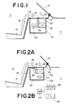
- a conventional air cleaning device 10 which is arranged to project into a trunk room T of the passenger motor vehicle at a position under a rear parcel shelf 12 behind a rear passenger seat 14, as shown.
- Designated by numeral 16 is a rear window pane which is located above the rear parcel shelf 12.
- the air cleaning device 10 comprises a housing 18 in which an air intake passage 20 and an air discharge passage 22 are defined by a partition member 24.
- the housing 18 is secured to the parcel shelf 12.
- Air intake openings 26 and air discharge openings 28 are formed in the rear parcel shelf 12 at positions to communicate with the air intake and discharge passages 20 and 22, respectively.
- An electric fan 30 is arranged in the air intake passage 20 for drawing the passenger compartment air into the passage 20 through the air intake openings 26.
- An air cleaner proper 32 such as an electrostatically operated air cleaner or a mechanical filter type air cleaner, is arranged in the air discharge passage 22 as shown.
- the air in the passenger compartment is drawn through the air intake openings 26 into the interior of the device 10 by the action of the electric fan 30.
- the air is cleaned by the air cleaner proper 32 and discharged into the passenger compartment through the air discharge openings 28.
- the cleaned air from the air discharge openings 28 flows along the rear window pane 16 and then spreads over the passenger compartment P.
- the housing 18 and the other parts of the device 10 are easily affected by the temperature of the trunk room T which is usually isolated from the passenger compartment P.
- the air fed into the cleaning device 10 is subjected to temperature drop causing a cooled air discharging from the openings 28.
- this undesired phenomenon gives the passengers on the rear seat 14 an unpleasant feeling.
- the air cleaning device 10 since the air cleaning device 10 has only the air cleaning function, it is impossible to deal with an over-dried condition in the passenger compartment which condition may be caused by the dehumidification effect brought by a long time heating or cooling by a heater or a cooler mounted to the vehicle.
- the over-dried condition of air will cause the passengers to have a sore throat and a problem in the nasal nucous membrane.
- the present invention is proposed by taking the above-mentioned problems into consideration.
- the air conditioning device 10A of this embodiment is mounted to the rear parcel shelf 12 to project into the trunk room T.
- the device 10A comprises a housing 18 secured to the parcel shelf 12.
- the housing 18 has an air intake passage 20 and an air discharge passage 22 which are bounded by a partition member 24.
- Air intake openings 26 and air discharge openings 28 are formed in the rear parcel shelf 12 to respectively communicate with the air intake and discharge passages 20 and 22.
- An air cleaner proper 32 is located in the air intake passage 20.
- An electric fan 30 is located in the air discharge passage 22 upstream of an electric heater 34 which is located in the air discharge passage 20 near the air discharge openings 28 as shown.
- the heater 34 has a temperature controller 36 such as a PTC thermometer, and is connected electrically to a motor 38 of the electric fan 30.
- the temperature controller 36 and the electric fan motor 38 are connected to a common switch 40 and operate when the switch 40 takes ON position.
- the passenger compartment air fed into the device 10A is first treated by the air cleaner proper 32 to be cleaned and then warmed by the heater 34 and then discharged into the passenger compartment P through the air discharge openings 28.
- the heater 34 By the provision of the heater 34, the above mentioned undesired phenomenon does not occur.
- the air conditioning device 10B of this embodiment is constructed small and mounted on the rear parcel shelf 12.
- the device 10B comprises a housing 18 mounted on the rear parcel shelf 12.
- the housing 18 has air intake openings 26 and air discharge openings 28 which are formed at opposed side walls of the housing 18 as shown.
- An air cleaner proper 32 is located near the air intake openings 26, while an electric heater 34 is located near the air discharge openings 28.
- An electric fan 30 is located between the air cleaner proper 32 and the electric heater 34. Since the entire of the air conditioning device 10B is arranged on the rear parcel shelf 12, that is, the device 10B has no portion which is projected into the trunk room T, the effect which the trunk room temperature applies to the air which flows in the device 10B is minimized.
- FIG. 4 of the drawings there is shown a third embodiment of the present invention. Similar to the first embodiment of Fig. 2A, the air conditioning device 10C of the third embodiment is mounted to the rear parcel shelf 12 to project into the trunk room T.
- the device 10C comprises a housing 18 secured to the rear parcel shelf 12.
- the housing 18 has an air intake passage 20 and an air discharge passage 22 which are bounded by a partition member 24.
- Air intake openings 26 and air discharge openings 28 are formed in the rear parcel shelf 12 at positions to communicate with the air intake and discharge passages 20 and 22 respectively.
- An air cleaner proper 32 is located in the air intake passage 32 and an electric fan 30 is located in an upstream portion of the-air discharge passage 22.
- Two electric heaters 34a and 34b are arranged in the air discharge passage 22, one of which is positioned near the air discharge openings 28, as shown.
- An additional passage 42 is branched from the air discharge passage 22 and terminates at a base section of the rear window pane 16.
- the other electric heater 34b is positioned near the entrance of the additional passage 42.
- a grille 44 is fixed to the exit portion of the additional passage 42, as shown.
- the air conditioning device 10D of this embodiment comprises a housing 18 which has an air intake passage 20 and an air discharge passage 22. These two passages 20 and 22 are connected by two parallelly arranged passages 46 and 48. An air cleaner proper 32 is located in the passage 48 and an electric heater 34 is in the other passage 46. A damper door 50 is swingably arranged in the air intake passage 20 to selectively open and close the passages 48 and 46. Air intake openings 26 and air discharge openings 28 are formed in the rear parcel shelf 12 at positions to respectively communicate with the air intake and discharge passages 20 and 22.
- Designated by numeral 52 is an electric switch which closes a circuit between the heater 34 and an electric power source (not shown) when the damper door 50 opens the passage 46 for the heater 34, and opens the circuit when the door 50 closes the passage 46.
- the damper door 50 takes a position to close the passage 46 for the heater 34.
- the air drawn into the air intake passage 20 is forced to flow through the-air cleaner proper 32.
- the air thus cleaned is discharged into the passanger compartment P.
- the damper door 50 takes the other position to open the passage 46 for the heater 34.
- the air drawn into the air intake passage 20 is forced to flow through the heater 34 without flowing through the air cleaner proper 32, so that from the air discharge openings 28, warmed air is discharged into the passenger compartment P.
- This operation compensates the temperature drop which may be caused by the construction of the air conditioning device 10D projected into the trunk room T.
- the air conditioning device 10E of this embodiment uses an electric humidifier 54 as a substitute for the heater 34 and comprises a housing mounted to the rear parcel shelf 12 to project into the trunk room T.
- the housing 18 has an air intake passage 20 and an air discharge passage 22 which are connected by two independent passages 46 and 48.
- An air cleaner proper 32 is located in the air intake passage 20 and an electric fan 30 is in the air discharge passage 22.
- the humidifier 54 is arranged in the passage 46.
- a damper door 50 is swingably arranged in the housing 18 to selectively open and close the passages 46 and 48.
- an electric switch 52 may be connected to the damper door 52.
- the switch 52 is designed to close the circuit between the humidifier 54 and an electric power source (not shown) when the damper door opens the passage 46, and open the circuit when the damper door 50 closes the passage 46. Further, if desired, a cooler may be used as a substitute for the humidifier 54.
- the air conditioning device 10F of this embodiment comprises a housing 18.
- the housing 18 has an air intake passage 20 and an air discharge passage 22 which are connected by two parallelly arranged passages 46 and 48.
- An air cleaner proper 32 is located in the passage 48 and a humidifier 54 is in the other passage 46.
- An electric fan 30 is arranged in the air discharge passage 22.
- a damper door 50 is swingably arranged in the housing 18 to selectively open and close the passages 46 and 48.
- the damper door 50 when the damper door 50 takes a position to open the passage 46 and simultaneously close the passage 48 as shown by the solid line, the air drawn into the air intake passage 20 is forced to flow through only the humidifier 54 to be damped and then discharged from the air discharge openings 28 into the passenger compartment P. While, when the damper door 50 takes the other position to close the passage 46 and simultaneously open the passage 48 as shown by the phantom line, the air drawn into the air intake passage 20 is forced to flow through only the air cleaner proper 32 to be cleaned and then discharged into the passenger compartment P.
- an electric switch may be connected to the damper door 50.
- the electric switch is designed to close the circuit between the electric humidifier 54 and an electric power source (not shown) when the damper door 50 opens the passage 46, and open the circuit when the damper door 50 closes the passage 46. If the air cleaner proper 32 is of an electric type, the operation of the electric air cleaner 32 is so controlled as to be reversed to that of the humidifier 54.
- the air conditioning device 10G of this embodiment comprises a housing 18.
- the housing 18 has an air intake passage 20 and an air discharge passage 22 which are connected by two independent passages 46 and 48.
- An air cleaner proper 32 is arranged in the air intake passage 20, an electric heater 34 is in the air discharge passage 22 and an electric humidifier 54 is in the passage 46, as shown.
- An electric fan 30 is arranged in the air discharge passage 22 at the position upstream of the heater 34.
- a damper door 50 is swingably arranged in the housing to selectively close and open the passages 46 and 48.
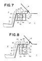
- the air conditioning device 10H of this embodiment comprises a housing 18 secured to the rear parcel shelf 12.
- the housing 18 has an air intake passage 20 and an air discharge passage 22 which are connected by two parallelly arranged passages 46 and 48.
- An air cleaner proper 32 is arranged in the passage 48 and an electric humidifier 54 is in the other passage 46.
- An electric heater 34 is arranged in the air discharge passage 22 at a position downstream of an electric fan 30 which is also located in the air discharge passage 22.
- a damper door 50 is swingably arranged in the air intake passage 20 to selectively open and close the two parallelly arranged passages 46 and 48.
- the damper door 50 takes a position to open the passage 46 and simultaneously close the other passage 48 as shown by the solid line, the air drawn into the air intake passage 20 is forced to flow through the electric humidifier 46 to be damped and then through the electric heater 34 to be wamred. Thus, damped and warmed air is discharged from the air discharge openings 28 into the passenger compartment P. While, when the damper door 50 takes the other position to close the passage 46 and simultaneously open the passage 48 as shown by the phantom line, the air dranw into the air intake passage 20 is forced to flow through the air cleaner proper 32 and then through the electric heater 34. Thus, from the air discharge openings 28, cleaned and warmed air is discharged into the passenger compartment P.
- FIG. 10 there is shown a ninth embodiment of the present invention.
- the air conditioning device 10I of this embodiment is a slight modification of the device 10H of the above-mentioned eighth embodiment.
- an additional passage 42 is branched from the air discharge passage 22 at a position downstream of the electric fan 30 and terminates at the base section of the rear window pane 16.
- a grille 44 is fixed to the exit portion of the additonal passage 42.
- the electric heater 34 is located in the additional passage 42. With this construction, the heated air in the additional passage 42 is forced to flow along the rear window pane 16 thereby preventing the pane 16 from being frosted.
- the air conditioning device is constructed to have at least one of a heater and a humidifier in addition to the air cleaner proper.
Landscapes
- Engineering & Computer Science (AREA)
- Mechanical Engineering (AREA)
- Physics & Mathematics (AREA)
- Thermal Sciences (AREA)
- Air-Conditioning For Vehicles (AREA)
Applications Claiming Priority (2)
| Application Number | Priority Date | Filing Date | Title |
|---|---|---|---|
| JP60595/80U | 1980-05-06 | ||
| JP1980060595U JPS56161814U (de) | 1980-05-06 | 1980-05-06 |
Publications (2)
| Publication Number | Publication Date |
|---|---|
| EP0039468A2 true EP0039468A2 (de) | 1981-11-11 |
| EP0039468A3 EP0039468A3 (de) | 1983-09-07 |
Family
ID=13146739
Family Applications (1)
| Application Number | Title | Priority Date | Filing Date |
|---|---|---|---|
| EP81103191A Withdrawn EP0039468A3 (de) | 1980-05-06 | 1981-04-28 | Klimaanlage |
Country Status (3)
| Country | Link |
|---|---|
| US (1) | US4401013A (de) |
| EP (1) | EP0039468A3 (de) |
| JP (1) | JPS56161814U (de) |
Cited By (2)
| Publication number | Priority date | Publication date | Assignee | Title |
|---|---|---|---|---|
| EP1502781A3 (de) * | 2003-07-07 | 2005-06-29 | Mazda Motor Corporation | Klimaanlage und ihre Verwendung bei einem Kraftfahrzeug |
| US7185725B2 (en) | 2003-07-07 | 2007-03-06 | Mazda Motor Corporation | Layout structure of driving device for vehicle |
Families Citing this family (24)
| Publication number | Priority date | Publication date | Assignee | Title |
|---|---|---|---|---|
| JPS5843339A (ja) * | 1981-09-09 | 1983-03-14 | Nippon Soken Inc | 加湿器 |
| JPS58133911A (ja) * | 1982-02-01 | 1983-08-09 | Nissan Motor Co Ltd | 空気調和装置 |
| JPS61205511A (ja) * | 1985-03-08 | 1986-09-11 | Nissan Motor Co Ltd | 自動車用加湿装置 |
| US4711159A (en) * | 1986-09-23 | 1987-12-08 | Armbruster Joseph M | Built-in vehicle air filtration system |
| US4874036A (en) * | 1987-07-14 | 1989-10-17 | Sanden Corporation | Heating and air conditioning system for a forklift |
| IT1227961B (it) * | 1988-10-07 | 1991-05-20 | Giudici Ermete Srl | Apparecchio per il riscaldamento e l'umidificazione dell'aria ambientale mediante elettroventilazione |
| AU669281B2 (en) * | 1993-03-12 | 1996-05-30 | F F Seeley Nominees Pty Ltd | Heater attachment for evaporative cooler |
| EP0640202B1 (de) * | 1993-03-12 | 2000-06-21 | F F SEELEY NOMINEES PTY. Ltd | Zusatzheizgerät für verdampfungskühler |
| JP3321314B2 (ja) * | 1994-09-30 | 2002-09-03 | 株式会社日本クライメイトシステムズ | 車両用後方空気調和装置 |
| US6003593A (en) | 1995-10-31 | 1999-12-21 | Denso International America, Inc. | Automotive vehicle climate control system |
| JP3281302B2 (ja) * | 1997-11-04 | 2002-05-13 | サンデン株式会社 | 車両用空調装置 |
| JPH11139145A (ja) * | 1997-11-04 | 1999-05-25 | Sanden Corp | 建設車両用空調装置 |
| DE19908499C1 (de) * | 1999-02-26 | 2000-04-20 | Daimler Chrysler Ag | Windschottanordnung |
| DE19908502C1 (de) * | 1999-02-26 | 2000-05-04 | Daimler Chrysler Ag | Offenes Kraftfahrzeug |
| US7328058B2 (en) * | 2000-01-04 | 2008-02-05 | Gamma Medica-Ideas, Inc. | Intravascular imaging detector |
| DE10157497A1 (de) * | 2001-11-23 | 2003-06-12 | Daimler Chrysler Ag | Heiz- und/oder Klimaanlage |
| EP1457369B1 (de) * | 2003-03-12 | 2009-08-26 | Behr France Rouffach SAS | Zusatzklimaanlage für ein Kraftfahrzeug |
| DE102004019607A1 (de) * | 2004-04-22 | 2006-01-12 | Webasto Ag | Heiz- und Klimatisierungssystem für ein Kraftfahrzeug |
| US20090260377A1 (en) * | 2004-04-22 | 2009-10-22 | Gerard Miller | Heating and air-conditioning system for a motor vehicle |
| DE102004024615B4 (de) * | 2004-05-18 | 2008-08-28 | Airbus Deutschland Gmbh | Vorrichtung zur Befeuchtung der Luft in einer Kabine eines Passagier- oder Frachtflugzeugs |
| JP4591427B2 (ja) * | 2006-09-06 | 2010-12-01 | トヨタ自動車株式会社 | 車両搭載物空冷構造 |
| JP4492602B2 (ja) * | 2006-10-26 | 2010-06-30 | パナソニック電工株式会社 | 車両用静電霧化装置 |
| JP6535990B2 (ja) * | 2014-08-01 | 2019-07-03 | 株式会社デンソー | 暖房装置 |
| US20180178631A1 (en) * | 2016-12-27 | 2018-06-28 | Komatsu Ltd. | Heater apparatus and work vehicle |
Family Cites Families (13)
| Publication number | Priority date | Publication date | Assignee | Title |
|---|---|---|---|---|
| US2725605A (en) * | 1950-04-24 | 1955-12-06 | Haltenberger Jules | Automobile glass defrosting and drying |
| US2853932A (en) * | 1953-06-22 | 1958-09-30 | Frank B Freydl | Ventilating attachment for vehicles |
| US2720149A (en) * | 1953-09-21 | 1955-10-11 | Groene Willard Le Blond | Automobile air conditioning duct system |
| US2717148A (en) * | 1953-11-19 | 1955-09-06 | Hall Michael Frank | Air cleaner and humidifier |
| US2761291A (en) * | 1954-06-09 | 1956-09-04 | Studebaker Packard Corp | Air duct for automobile cooling system |
| US2970456A (en) * | 1958-07-02 | 1961-02-07 | Charles R Blake | Automobile cooling unit |
| FR1387145A (fr) * | 1963-12-02 | 1965-01-29 | Renault | Perfectionnements à la climatisation des véhicules automobiles |
| US3286617A (en) * | 1964-10-21 | 1966-11-22 | Chrysler Corp | Vehicle body interior ventilation arrangement |
| US3329077A (en) * | 1964-11-03 | 1967-07-04 | Fiat Spa | Air conditioning on motor vehicles |
| US3651659A (en) * | 1969-06-30 | 1972-03-28 | Shikibo Ltd | Air-conditioning apparatus in vehicle |
| US3718281A (en) * | 1971-12-09 | 1973-02-27 | Gen Motors Corp | Thermostatic vacuum positioner |
| DE2236152A1 (de) * | 1972-07-22 | 1974-02-07 | Kopat Ges Fuer Konstruktion En | Verfahren und vorrichtung zum versorgen von einmotorigen fahrzeugen, insbesondere kraftwagen aller art, mit elektrischer hilfsenergie |
| SE423356B (sv) * | 1978-04-18 | 1982-05-03 | Saab Scania Ab | Arrangemang for rening av inledande luft till ett fordons kupeutrymme |
-
1980
- 1980-05-06 JP JP1980060595U patent/JPS56161814U/ja active Pending
-
1981
- 1981-04-28 EP EP81103191A patent/EP0039468A3/de not_active Withdrawn
- 1981-04-29 US US06/258,626 patent/US4401013A/en not_active Expired - Fee Related
Cited By (2)
| Publication number | Priority date | Publication date | Assignee | Title |
|---|---|---|---|---|
| EP1502781A3 (de) * | 2003-07-07 | 2005-06-29 | Mazda Motor Corporation | Klimaanlage und ihre Verwendung bei einem Kraftfahrzeug |
| US7185725B2 (en) | 2003-07-07 | 2007-03-06 | Mazda Motor Corporation | Layout structure of driving device for vehicle |
Also Published As
| Publication number | Publication date |
|---|---|
| JPS56161814U (de) | 1981-12-02 |
| US4401013A (en) | 1983-08-30 |
| EP0039468A3 (de) | 1983-09-07 |
Similar Documents
| Publication | Publication Date | Title |
|---|---|---|
| US4401013A (en) | Air conditioning device | |
| US6871696B2 (en) | Vehicle seat air conditioning system | |
| US4376408A (en) | Air circulation system in a vehicle compartment of an automotive vehicle | |
| US20020153132A1 (en) | Air conditioning system for automotive vehicles | |
| JPH11105532A (ja) | 車両用空調装置 | |
| JP3997346B2 (ja) | 自動車の暖房装置または空調装置内で混合空気を制御するための方法および配置 | |
| JP3675161B2 (ja) | 車両用シート空調装置 | |
| JPS608110A (ja) | 自動車用空調装置 | |
| JP3675160B2 (ja) | 車両用シート空調装置 | |
| JPS60255522A (ja) | 自動車用空調装置 | |
| JP3314692B2 (ja) | 車両用空調装置 | |
| US3105431A (en) | Motor vehicle construction | |
| JPS6280118A (ja) | 自動車用空気調和装置 | |
| JPH0645293B2 (ja) | 自動車用空調装置 | |
| JPS6324844B2 (de) | ||
| JP3275322B2 (ja) | 車両用空気調和装置 | |
| JP3627767B2 (ja) | 車両用空調装置 | |
| KR0115918Y1 (ko) | 차량히터의 공기분배구조 | |
| KR19990021517A (ko) | 좌우독립 온도 조절식 공조 유니트 | |
| JPS6323002B2 (de) | ||
| KR0143595B1 (ko) | 대형버스용 공기조화장치 | |
| KR20010109987A (ko) | 자동차용 공기조화장치 | |
| JPS625808B2 (de) | ||
| JPS63130421A (ja) | 自動車用空調装置 | |
| KR970020542A (ko) | 자동차의 공조 덕트 시스템 |
Legal Events
| Date | Code | Title | Description |
|---|---|---|---|
| PUAI | Public reference made under article 153(3) epc to a published international application that has entered the european phase |
Free format text: ORIGINAL CODE: 0009012 |
|
| AK | Designated contracting states |
Designated state(s): DE FR GB |
|
| PUAL | Search report despatched |
Free format text: ORIGINAL CODE: 0009013 |
|
| AK | Designated contracting states |
Designated state(s): DE FR GB |
|
| 17P | Request for examination filed |
Effective date: 19830922 |
|
| RAP1 | Party data changed (applicant data changed or rights of an application transferred) |
Owner name: NISSAN MOTOR CO., LTD. |
|
| STAA | Information on the status of an ep patent application or granted ep patent |
Free format text: STATUS: THE APPLICATION IS DEEMED TO BE WITHDRAWN |
|
| 18D | Application deemed to be withdrawn |
Effective date: 19860617 |
|
| RIN1 | Information on inventor provided before grant (corrected) |
Inventor name: MUTO, YOSHIHIKO Inventor name: OHASHI, TOSHIO Inventor name: TAKASAKI, MASARU |