EP0039539A2 - Schwimmender Spannkeil für einen indexierbaren Schneideinsatz - Google Patents
Schwimmender Spannkeil für einen indexierbaren Schneideinsatz Download PDFInfo
- Publication number
- EP0039539A2 EP0039539A2 EP81301351A EP81301351A EP0039539A2 EP 0039539 A2 EP0039539 A2 EP 0039539A2 EP 81301351 A EP81301351 A EP 81301351A EP 81301351 A EP81301351 A EP 81301351A EP 0039539 A2 EP0039539 A2 EP 0039539A2
- Authority
- EP
- European Patent Office
- Prior art keywords
- main body
- body member
- swivel plate
- insert
- trailing
- Prior art date
- Legal status (The legal status is an assumption and is not a legal conclusion. Google has not performed a legal analysis and makes no representation as to the accuracy of the status listed.)
- Granted
Links
Images

Classifications
-
- B—PERFORMING OPERATIONS; TRANSPORTING
- B23—MACHINE TOOLS; METAL-WORKING NOT OTHERWISE PROVIDED FOR
- B23C—MILLING
- B23C5/00—Milling-cutters
- B23C5/16—Milling-cutters characterised by physical features other than shape
- B23C5/20—Milling-cutters characterised by physical features other than shape with removable cutter bits or teeth or cutting inserts
- B23C5/22—Securing arrangements for bits or teeth or cutting inserts
- B23C5/24—Securing arrangements for bits or teeth or cutting inserts adjustable
- B23C5/2475—Securing arrangements for bits or teeth or cutting inserts adjustable the adjusting means being distance elements, e.g. shims or washers
-
- B—PERFORMING OPERATIONS; TRANSPORTING
- B23—MACHINE TOOLS; METAL-WORKING NOT OTHERWISE PROVIDED FOR
- B23C—MILLING
- B23C5/00—Milling-cutters
- B23C5/16—Milling-cutters characterised by physical features other than shape
- B23C5/20—Milling-cutters characterised by physical features other than shape with removable cutter bits or teeth or cutting inserts
- B23C5/22—Securing arrangements for bits or teeth or cutting inserts
- B23C5/2265—Securing arrangements for bits or teeth or cutting inserts by means of a wedge
- B23C5/2269—Securing arrangements for bits or teeth or cutting inserts by means of a wedge for plate-like cutting inserts
-
- Y—GENERAL TAGGING OF NEW TECHNOLOGICAL DEVELOPMENTS; GENERAL TAGGING OF CROSS-SECTIONAL TECHNOLOGIES SPANNING OVER SEVERAL SECTIONS OF THE IPC; TECHNICAL SUBJECTS COVERED BY FORMER USPC CROSS-REFERENCE ART COLLECTIONS [XRACs] AND DIGESTS
- Y10—TECHNICAL SUBJECTS COVERED BY FORMER USPC
- Y10T—TECHNICAL SUBJECTS COVERED BY FORMER US CLASSIFICATION
- Y10T407/00—Cutters, for shaping
- Y10T407/19—Rotary cutting tool
- Y10T407/1906—Rotary cutting tool including holder [i.e., head] having seat for inserted tool
- Y10T407/1908—Face or end mill
- Y10T407/192—Face or end mill with separate means to fasten tool to holder
- Y10T407/1922—Wedge clamp element
-
- Y—GENERAL TAGGING OF NEW TECHNOLOGICAL DEVELOPMENTS; GENERAL TAGGING OF CROSS-SECTIONAL TECHNOLOGIES SPANNING OVER SEVERAL SECTIONS OF THE IPC; TECHNICAL SUBJECTS COVERED BY FORMER USPC CROSS-REFERENCE ART COLLECTIONS [XRACs] AND DIGESTS
- Y10—TECHNICAL SUBJECTS COVERED BY FORMER USPC
- Y10T—TECHNICAL SUBJECTS COVERED BY FORMER US CLASSIFICATION
- Y10T407/00—Cutters, for shaping
- Y10T407/19—Rotary cutting tool
- Y10T407/1906—Rotary cutting tool including holder [i.e., head] having seat for inserted tool
- Y10T407/1934—Rotary cutting tool including holder [i.e., head] having seat for inserted tool with separate means to fasten tool to holder
- Y10T407/1938—Wedge clamp element
- Y10T407/194—Resilient clamp jaw
-
- Y—GENERAL TAGGING OF NEW TECHNOLOGICAL DEVELOPMENTS; GENERAL TAGGING OF CROSS-SECTIONAL TECHNOLOGIES SPANNING OVER SEVERAL SECTIONS OF THE IPC; TECHNICAL SUBJECTS COVERED BY FORMER USPC CROSS-REFERENCE ART COLLECTIONS [XRACs] AND DIGESTS
- Y10—TECHNICAL SUBJECTS COVERED BY FORMER USPC
- Y10T—TECHNICAL SUBJECTS COVERED BY FORMER US CLASSIFICATION
- Y10T407/00—Cutters, for shaping
- Y10T407/22—Cutters, for shaping including holder having seat for inserted tool
- Y10T407/2222—Tool adjustable relative to holder
- Y10T407/2252—Rectilinearly
- Y10T407/2256—Rectilinearly including wedge clamp element
- Y10T407/2258—And guide or detent
-
- Y—GENERAL TAGGING OF NEW TECHNOLOGICAL DEVELOPMENTS; GENERAL TAGGING OF CROSS-SECTIONAL TECHNOLOGIES SPANNING OVER SEVERAL SECTIONS OF THE IPC; TECHNICAL SUBJECTS COVERED BY FORMER USPC CROSS-REFERENCE ART COLLECTIONS [XRACs] AND DIGESTS
- Y10—TECHNICAL SUBJECTS COVERED BY FORMER USPC
- Y10T—TECHNICAL SUBJECTS COVERED BY FORMER US CLASSIFICATION
- Y10T407/00—Cutters, for shaping
- Y10T407/22—Cutters, for shaping including holder having seat for inserted tool
- Y10T407/2272—Cutters, for shaping including holder having seat for inserted tool with separate means to fasten tool to holder
- Y10T407/2282—Cutters, for shaping including holder having seat for inserted tool with separate means to fasten tool to holder including tool holding clamp and clamp actuator
- Y10T407/2284—Wedge clamp element
-
- Y—GENERAL TAGGING OF NEW TECHNOLOGICAL DEVELOPMENTS; GENERAL TAGGING OF CROSS-SECTIONAL TECHNOLOGIES SPANNING OVER SEVERAL SECTIONS OF THE IPC; TECHNICAL SUBJECTS COVERED BY FORMER USPC CROSS-REFERENCE ART COLLECTIONS [XRACs] AND DIGESTS
- Y10—TECHNICAL SUBJECTS COVERED BY FORMER USPC
- Y10T—TECHNICAL SUBJECTS COVERED BY FORMER US CLASSIFICATION
- Y10T407/00—Cutters, for shaping
- Y10T407/22—Cutters, for shaping including holder having seat for inserted tool
- Y10T407/2272—Cutters, for shaping including holder having seat for inserted tool with separate means to fasten tool to holder
- Y10T407/2282—Cutters, for shaping including holder having seat for inserted tool with separate means to fasten tool to holder including tool holding clamp and clamp actuator
- Y10T407/2286—Resiliently biased clamp jaw
-
- Y—GENERAL TAGGING OF NEW TECHNOLOGICAL DEVELOPMENTS; GENERAL TAGGING OF CROSS-SECTIONAL TECHNOLOGIES SPANNING OVER SEVERAL SECTIONS OF THE IPC; TECHNICAL SUBJECTS COVERED BY FORMER USPC CROSS-REFERENCE ART COLLECTIONS [XRACs] AND DIGESTS
- Y10—TECHNICAL SUBJECTS COVERED BY FORMER USPC
- Y10T—TECHNICAL SUBJECTS COVERED BY FORMER US CLASSIFICATION
- Y10T407/00—Cutters, for shaping
- Y10T407/22—Cutters, for shaping including holder having seat for inserted tool
- Y10T407/2272—Cutters, for shaping including holder having seat for inserted tool with separate means to fasten tool to holder
- Y10T407/2282—Cutters, for shaping including holder having seat for inserted tool with separate means to fasten tool to holder including tool holding clamp and clamp actuator
- Y10T407/229—Pivoted jaw
Definitions
- This invention relates to a new and improved floating wedge for use in conjunction with an indexable cutting tool. More particularly, a floating wedge is provided which is receivable in an insert pocket of a cutting tool for securing an indexable insert therein.
- the floating wedge of the subject invention consists of cwo members which are relatively movable such that the orientation of the leading surface of the wedge may be altered to achieve full contact pressure between the insert, wedge and insert pocket, thereby eliminating localized stress which can lead to failure of the insert.
- various wedge retention systems have been devised for securing an indexable insert within an insert pocket of a cutting tool.
- the cutting tool which for example, may be of the type which is intended to be rotated about a central axis, is provided with at least one insert pocket which is adapted to receive an indexable cutting insert having opposed planar rake surfaces and a plurality of sharpened edge faces.
- the insert pocket has opposed generally planar leading and trailing walls.
- an insert is mounted in the pocket and is secured therein by a wedge.
- the wedge is readily removable to allow the indexing of the insert when the exposed cutting edge becomes worn.
- the cutting tool In a cutting operation, relatively strong forces are exerted on the cutting edges of the insert.
- the cutting tool In order to prevent the insert from shifting within the insert pocket, the cutting tool is designed such that the wedge securely presses the insert against a wall of the pocket, at a point on the insert adjacent the upper edge of a rake face. While this arrangement functions to maintain the insert within the pocket, localized stresses arise at the points of contact which tend to cause the inserts to crack or fracture. Further after a period of use, an insert may shift into an out of parallel orientation which will also cause localized stresses to develop.
- Ceramic inserts while advantageous in certain operations, such as the milling of cast iron parts in the auto industry, tend to be relatively brittle and will fracture easily if subjected to localized stresses.
- the insert pockets of the cutting tool must be accurately machined to precise gauge tolerances such that full and equal contact pressure is established between the pocket wall and the insert, thereby reducing localized stresses.
- the machining of insert pockets to fine tolerances is time consuming and expensive. Further, even when the pockets are properly machined, the inserts may still shift to an out of parallel orientation wherein localized stresses will develop.
- the invention attempts to provide a new and improved floating wedge which enables full and equal contact pressure to be established between the walls of the insert pocket and the insert, thereby eliminating localized stresses which will result in insert fracture.
- the invention also attempts to provide a floating wedge which will inhibit the development of localized stresses and eliminate the necessity of machining an insert pocket to highly accurate gauge tolerances.
- the present invention attempts to provide a floating wedge consisting of a main body member and a swivel plate member which are capable of relative movement such that the orientation of the leading surface of the wedge relative to the trailing surface of the wedge may be adjusted, to facilitate the alignment of the insert within the insert pocket.
- the invention attempts to provide a wedge assembly wherein both the axial and radial float may be adjusted when mounting an insert in a cutting tool.
- a new and improved floating wedge is provided and is intended for use with an indexable cutting tool including an insert pocket having opposed leading and trailing walls.
- leading and trailing relate to the direction of rotation of the cutting tool with the leading surface preceding the trailing surface, however the terms are used only for orientation purposes and are not intended to limit the scope of the subject invention.
- the floating wedge of the subject invention includes a main body member having opposed leading and trailing surfaces, with the trailing surface thereof being adapted to abut the trailing wall of the insert pocket.
- the floating wedge further includes a swivel plate member having opposed leading and trailing surfaces, with the leading surface thereof being substantially planar and adapted to abut one of the planar rake surfaces of the indexable insert.
- the trailing surface of the swivel plate member and the leading surface of the main body member are disposed in abutting relationship and are provided with complementary configurations which enable the relative slidable movement therebetween.
- the orientation of the planar leading surface of the swivel plate member relative to the trailing surface of the main body member may be adjusted to securely seat the insert within the insert pocket in a position wherein full and equal contact pressure is achieved along the rake faces of the insert.
- the leading surface of the main body member and the trailing surface of the swivel plate member are arcuate in configuration which functions to limit the relative movement between said members.
- An engagement means may be provided between the abutting surfaces of the main body member and the swivel plate member which in combination with the arcuate configuration of the members, functions to restrict the relative movement of the members about a predetermined axis of rotation.
- the engagement means comprises a tongue and groove arrangement formed in the abutting surfaces of the members. The tongue and groove arrangement may be dovetail in configuration to maintain the members in abutting relationship and enhance the stability of the wedge.
- a spring is provided which connects the members and maintains them in abutting relationship.
- the trailing surface of the main body member and the abutting trailing wall of the insert pocket be provided with complementary configurations.
- This arrangement permits the relative movement between the main body member and the wall of the insert pocket which varies the orientation of the leading surface of the swivel plate member.
- the opposed complementary surfaces may be arcuate in configuration which functions to constrain the relative movement therebetween about a predetermined axis of rotation.
- the curvature of the trailing surface of the main body portion be disposed such that the predetermined axis of rotation is perpendicular to the axis of rotation between the main body member and the swivel plate member thereby enabling the adjustment of both the radial and axial float.
- the above described floating wedge enables the orientation of the front planar surface of the swivel plate to be readily adjusted, relative to the walls of the insert pocket, such that full and equal contact pressure may be achieved between the insert, wedge and insert pocket to minimize the development of localized stresses and reduce the likelihood of insert fracture.
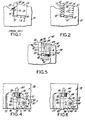
- FIG. 1 there is illustrated a wedge assembly and an insert pocket as used in the prior art. More particularly, a portion of the body of a cutting tool 10 is illustrated which includes an insert pocket 12 having opposed leading and trailing walls 14 and 16.
- the insert pocket 12 is adapted to receive an indexable insert 20 having opposed, planar front and rear rake surfaces 22 and 24.
- the indexable insert 20 is securely mounted into the insert pocket 12 by means of an adjustable wedge member 26, having opposed leading and trailing surface 28 and 30.
- the wedge 26 is driven radially inwardly in the direction indicated by arrow A, until the insert 20 is securely seated.
- the insert 20 is initially placed in the pocket 12 with an edge face of the insert abutting the locating rail 32 of the insert pocket.
- the wedge 26 is driven radially inwardly with the trailing surface 30 thereof abutting the trailing wall 16 of the insert pocket, while the leading surface 28 of the wedge 26 abuts the rear planar surface 24 of the insert.
- the wedge is tightened until the insert 20 is securely locked in preparation for a cutting operation.
- the insert pocket 12 is designed such that the insert is clamped between the leading wall 14 of the pocket, and the wedge.
- contact pressure as indicated by arrows in Figure 1 is established at a point B adjacent the cutting edge of the insert to prevent the insert 20 from shifting during the cutting operation.
- this arrangement while functioning to keep the insert in place, gives rise to localized stresses at the contact point B. The development of localized stresses tends to cause the insert to fracture and break down.
- the new and improved floating wedge of the subject invention is adapted for use with an indexable cutting tool 38 having at least one insert pocket 42 therein.
- the floating wedge indicated generally by the numeral 40, which consists of a main body member 44 and a swivel plate member 46, is receivable within the insert pocket 42 for securing an insert 48 therein.
- the insert pocket 42 is provided with opposed leading and trailing walls 50 and 52.
- a chip removal recess 53 is provided adjacent the leading wall 50 of the pocket to aid in channeling metal particles away from the insert 48 during a cutting operation.
- Trailing wall 52 has an arcuate concave configuration and has a curvature substantially similar to the curvature of the trailing surface of the main body member 44.
- a locating rail 54 is provided on the bottom surface of the insert pocket 42 for controlling the radial rake of the insert.
- a threaded aperture 55 is also provided on the bottom wall of the insert pocket.
- the axial location of the insert 48 is fixed by the rest pad 56 (as illustrated in Figure 4) which is secured within the insert pocket 42 by means of a differential set screw 58.
- Set screw 58 is provided with a non-circular recess 62 to facilitate the tightening of the screw by a suitable driver to secure the rest pad 56 within the insert pocket and fix the axial position of the insert 48.
- the indexable insert 48 which is generally square in configuration, has opposed planar rake surfaces 64 and 66 with a plurality of edge faces 68 disposed therebetween. While the subject invention is illustrated in combination with a square planar insert, it will be apparent to one skilled in the art that the subject invention may be modified for use with other types of insert shapes and configurations, as well with both negative and positively cleared inserts.
- floating wedge 40 coacts with the walls of the pocket 42 to securely seat insert 48 therein.
- the floating wedge includes a swivel plate member 46 having opposed leading and trailing surfaces 70 and 72.
- the leading surface 70 of the swivel plate member 46 is provided with a configuration conforming to the configuration of the rear rake surface 66 of the insert 48 and in this case, is provided with a planar configuration.
- the trailing surface 72 of swivel plate member 46 is provided with an arcuate convex configuration.
- a longitudinally extending arcuate tongue 74 is provided on the trailing surface 72 of the swivel plate 46 and is adapted for engagement with a groove in the main body member 44 of the wedge 40, as more fully described hereinafter.
- the main body member 44 is provided with opposed leading and trailing surfaces 80 and 82.
- the leading surface 80 of the main body member 44 is provided with a configuration which is complementary to the configuration of the trailing surface 72 of the swivel plate member 46.
- the leading surface 80 has an arcuate, concave configuration, with a curvature substantially similar to the curvature of the convex trailing surface 72 of the swivel plate member 46. While complementary arcuate configurations are illustrated in the drawings, it is intended that the scope of the subject invention include any complementary configuration, for example, a hemispherical configuration, which will permit the relative slidable movement between the swivel plate member 46 and the main body member 44.
- the leading surface 80 of the main body member 44 further includes a groove 84 which is configured to receive the tongue 74 of the rear surface 72 of swivel plate member 46.
- the tongue and groove arrangement in combination with the complementary arcuate configuration of the opposed surfaces of the floating wedge 40, functions to constrain the relative movement between the members about a predetermined axis of rotation, corresponding to the central axis of the curved surfaces.
- the trailing surface 82 of the main body member 44 is provided with an arcuate, convex configuration having a radius of curvature substantially similar to the curvature of the concave trailing wall 52 of the insert pocket 42.
- the central axis of the arcuate trailing surface 82 of the main body member 44 is perpendicular to the central axis of the arcuate leading surface 80, such that the adjustments to the orientation of the swivel plate member 46 relative to the insert pocket 42 may be made in two dimensions.
- both the axial and radial float of the front surfaces 70 of the swivel plate member 46 may be adjusted to eliminate localized stresses.
- the main body member 44 is further provided with a threaded central aperture 86 extending therethrough which is adapted to receive a differential screw 90.
- Differential screw 90 is provided with radially outer and inner threaded portions 92 and 94 which are threaded in opposite directions.
- the radially outer threaded portion 92 is adapted to be engaged in the central aperture 86 of the main body member 44, while the radially inward threaded portion 94 of screw 90 is adapted to be received in the aperture 55 in the bottom wall of the insert pocket.
- Differential screw 90 is provided with a non-circular recess 96 to facilitate the turning of the screw by a driver or other suitable tool. In use, the rotation of screw 90 will cause the radial position of the floating wedge 40 to be varied.
- a retaining spring 100 is provided to aid in maintaining the swivel plate member 46 and the main body member 44 in abutting relationship.
- Retaining spring 100 which is formed from approximately .02 inch (# 8) piano wire, is generally V-shaped in configuration and has two projecting pin portions 102 which extend perpendicularly from the plane of the V-confiruration.
- the swivel plate member 46 and the main body member 44 are provided with two cylindrical receiving channels 104 and 106 which are adapted to receive the pin portions 102 of retaining spring 100.
- an edge face 68 of the insert is placed in abutting relationship with the rest pad 56 such that the axial position of the rest pad fixes the axial overhang of the insert.
- the insert 48 is then securely mounted within the insert pocket 42 by tightening the floating wedge 40 within the pocket. More particularly, the floating wedge 40 is shifted radially inwardly (in the direction of arrow E in Figure 5) until the insert is securely locked in place.
- the floating wedge 40 is adjusted radially inwa..dly by rotating differential screw 90 using an appropriate driver engaged in the non-circular recess 96 provided in the top of the differential screw 90.
- the swivel plate member 46 will slide, relative to the main body member 44, such that a radially parallel relationship will be established between the leading surface 70 of the swivel plate 46 and the leading wall 50 of the insert pocket with the insert disposed therebetween.
- the opposed complementary configuration of the abutting surfaces of the swivel plate member 46 and the main body member 44 permit the slidable movement therebetween.
- restraining spring 100 is flexible and does not inhibit the relative movement of the members.
- the complementary curvatures of members 44 and 46 in combination with the tongue 74 and groove 84 arrangement therebetween functions to contarain the relative movement of the members about a single predetermined axis of rotation, thereby enabling the adjustment of the radial float.
- the trailing surface 82 of the main body member 44 is provided with an arcuate configuration having a central axis which is perpendicular to the central axis of the arcuate leading surface 80.
- the trailing wall 52 of the insert pocket is provided with a complementary arcuate configuration.
- both the axial and radial float are automatically varied until a parallel configuration is achieved between the leading surface 70 of the swivel plate member 46, the insert 48 and the leading wall 50 of the insert pocket.
- Figure 6 illustrates a second embodiment of the subject invention wherein like members are used to designate like parts.
- the tongue 74' of the swivel plate member 46 is provided with a dovetail configuration and the groove 84' in the leading surface 80 of the main body member 44 is configured to receive the dovetail tongue 74'.
- the dovetail tongue and groove arrangement is provided to enhance the stability of the floating wedge 40 and functions to maintain the members 44, 46 in abutting relationship.
- the use of a retaining spring is unnecessary, since the dovetail tongue and groove arrangement maintains the members in abutting relationship, while permitting relative movement therebetween.
- the operation of the second embodiment of the floating wedge 40 is similar to the operation of the first embodiment.
- the complementary configurations of the abutting surfaces of members 44, 46 permits relative movement therebetween such that the radial float is automatically adjusted, thereby achieving a radially parallel configuration.
- the complementary configurations of the trailing surface 82 of the main body member 44 and the trailing wall 52 of the insert pocket 42 permits the axial float to be automatically adjusted providing an axially parallel configuration. Accordingly, the insert 48 and the wedge 40 will be securely mounted within the insert pocket, whereby full and equal contact pressure is established between the members 44, 46 and the walls of the pocket, thereby eliminating localized stresses and decreasing the likelihood of insert fracture during a cutting operation.
- applicant's invention provides for a new and improved floating wedge 40 consisting of a main body member 44 having opposed leading and trailing surfaces 80, 82 and a swivel plate member 46 also having opposed leading and trailing surfaces 70, 72, with the leading surface 80 of the main body member 44 and the trailing surface 72 of the swivel plate member being disposed in abutting relationship.
- the abutting surfaces are provided with complementary configurations which permits relative sliding movement between the respective members for adjusting the orientation of the leading surface 70 of the swivel plate member.
- the complementary configurations are arcuate and include a tongue and groove arrangenent for constraining the relative movement between the members about a predetermined axis of rotation to permit adjustment of the radial float of the wedge 40.
- the trailing surface 82 of the main body member 44 and the abutting trailing wall 52 of the insert pocket are also provided with complementary arcuate configurations which enable the relative movement between the wedge 40 and the wall 52 about a predetermined axis of rotation which is perpendicular to the axis of rotation between the swivel plate member 46 and the main body member 44.
- the relative movement between the swivel plate member 46, the main body member 44 and the trailing wall 52 of the insert pocket permits the automatic adjustment of both the axial and radial positions of the leading surface of the swivel plate member 46. More particularly, in use, as the floating wedge 40 is adjusted radially inwardly to secure the insert within the insert pocket, any out of parallel orientation of the insert will exert unequal forces on the floating wedge, such that the orientation of the wedge will shift until a parallel orientation is achieved between the wedge, the insert and the walls of the insert pocket.
- This parallel configuration functions to establish full and equal contact pressures, along the entire rake faces of the insert, thereby minimizing localized stresses and reducing the likelihood of insert fracture during a cutting operation.
Landscapes
- Engineering & Computer Science (AREA)
- Mechanical Engineering (AREA)
- Milling Processes (AREA)
- Cutting Tools, Boring Holders, And Turrets (AREA)
- Perforating, Stamping-Out Or Severing By Means Other Than Cutting (AREA)
- Knives (AREA)
Priority Applications (1)
| Application Number | Priority Date | Filing Date | Title |
|---|---|---|---|
| AT81301351T ATE8590T1 (de) | 1980-05-07 | 1981-03-27 | Schwimmender spannkeil fuer einen indexierbaren schneideinsatz. |
Applications Claiming Priority (2)
| Application Number | Priority Date | Filing Date | Title |
|---|---|---|---|
| US06/147,540 US4329091A (en) | 1980-05-07 | 1980-05-07 | Floating wedge for use in conjunction with an indexable cutting tool |
| US147540 | 1980-05-07 |
Publications (3)
| Publication Number | Publication Date |
|---|---|
| EP0039539A2 true EP0039539A2 (de) | 1981-11-11 |
| EP0039539A3 EP0039539A3 (en) | 1982-05-05 |
| EP0039539B1 EP0039539B1 (de) | 1984-07-25 |
Family
ID=22521988
Family Applications (1)
| Application Number | Title | Priority Date | Filing Date |
|---|---|---|---|
| EP81301351A Expired EP0039539B1 (de) | 1980-05-07 | 1981-03-27 | Schwimmender Spannkeil für einen indexierbaren Schneideinsatz |
Country Status (8)
| Country | Link |
|---|---|
| US (1) | US4329091A (de) |
| EP (1) | EP0039539B1 (de) |
| JP (1) | JPS578011A (de) |
| AT (1) | ATE8590T1 (de) |
| AU (1) | AU547665B2 (de) |
| BR (1) | BR8102859A (de) |
| DE (1) | DE3164976D1 (de) |
| ZA (1) | ZA812193B (de) |
Cited By (1)
| Publication number | Priority date | Publication date | Assignee | Title |
|---|---|---|---|---|
| DE102022213281A1 (de) * | 2022-12-08 | 2024-06-13 | Kennametal Inc. | Rotationswerkzeug, insbesondere Fräser |
Families Citing this family (39)
| Publication number | Priority date | Publication date | Assignee | Title |
|---|---|---|---|---|
| US4575287A (en) * | 1982-06-11 | 1986-03-11 | Kennametal Inc. | Milling cutter and method of assembling therefor |
| US4449556A (en) * | 1982-08-20 | 1984-05-22 | Wadkin Plc | Rotary cutter heads |
| JPH0729520Y2 (ja) * | 1985-05-14 | 1995-07-05 | 佐藤工業株式会社 | 汚染コンクリ−ト切削用フライスカツタ |
| US4662254A (en) * | 1985-12-09 | 1987-05-05 | Gte Valeron Corporation | Quick change tool block clamp |
| DE3611672A1 (de) * | 1986-04-07 | 1987-10-08 | Guehring Gottlieb Fa | Zerspanungswerkzeug |
| US4667713A (en) * | 1986-05-23 | 1987-05-26 | Weyerhaeuser Company | Chipper knife assembly |
| SE460772B (sv) * | 1988-03-11 | 1989-11-20 | Sandvik Ab | Fraesverktyg |
| US5102269A (en) * | 1989-06-20 | 1992-04-07 | Mitsubishi Materials Corporation | Insert cutter |
| GB9003697D0 (en) * | 1990-02-19 | 1990-04-18 | Iscar Hartmetall | A metal cutting tool |
| AT397219B (de) * | 1990-07-30 | 1994-02-25 | Plansee Tizit Gmbh | Rotierendes spanabhebendes werkzeug |
| JP2516133Y2 (ja) * | 1991-03-07 | 1996-11-06 | 三菱マテリアル株式会社 | 転削工具におけるチップのクランプ機構 |
| US5156501A (en) * | 1991-08-07 | 1992-10-20 | Gte Valenite Corporation | Adjustable torsion bar cartridge for face mills |
| US5147157A (en) * | 1991-08-07 | 1992-09-15 | Gte Valenite Corporation | Adjustable leaf spring cartridge for face mills |
| US6619882B2 (en) * | 2000-07-10 | 2003-09-16 | Rh Group Llc | Method and apparatus for sealing cracks in roads |
| US6386250B1 (en) * | 2000-10-30 | 2002-05-14 | Hsing-Chao Liu | Helical knife assembly |
| IL177613A0 (en) * | 2006-08-21 | 2006-12-10 | Iscar Ltd | A cutting insert adjustment device |
| USD757124S1 (en) | 2009-02-23 | 2016-05-24 | Fecon, Inc. | Land clearing tool interface |
| WO2009105752A2 (en) | 2008-02-22 | 2009-08-27 | Fecon, Inc. | Apparatus and method for land clearing and preparation |
| JP5338425B2 (ja) * | 2008-03-28 | 2013-11-13 | 三菱マテリアル株式会社 | インサート着脱式カッタ |
| JP5541930B2 (ja) * | 2009-01-08 | 2014-07-09 | 富士重工業株式会社 | 工具ヘッド |
| CN104768688B (zh) * | 2012-11-09 | 2017-04-26 | 格里森工场 | 具有条形刀片的径向可调整性的齿轮刀具 |
| CN105228784B (zh) * | 2013-04-25 | 2019-02-05 | 格里森工场 | 用于锥齿轮切削的具有有效安置棒型刀片的切削工具 |
| KR101524286B1 (ko) * | 2014-01-17 | 2015-05-29 | 한국야금 주식회사 | 절삭공구의 인서트 착탈 장치 |
| DE102014119094A1 (de) * | 2014-12-18 | 2016-06-23 | Hartmetall-Werkzeugfabrik Paul Horn Gmbh | Spanabhebendes Werkzeug |
| JP5980360B1 (ja) * | 2015-02-27 | 2016-08-31 | 株式会社牧野フライス製作所 | フライス工具 |
| EP3246117A1 (de) * | 2016-05-20 | 2017-11-22 | Seco Tools Ab | Schneidwerkzeug und unterlegscheibe |
| CH713020A1 (de) * | 2016-10-10 | 2018-04-13 | Oertli Werkzeuge Ag | Messerkopf und Messerkopfsystem, insbesondere für eine Holzbearbeitungsmaschine. |
| USD835680S1 (en) | 2017-01-24 | 2018-12-11 | Fecon, Inc. | Land clearing tool interface |
| USD835681S1 (en) | 2017-01-24 | 2018-12-11 | Fecon, Inc. | Land clearing tool interface |
| USD836137S1 (en) | 2017-01-24 | 2018-12-18 | Fecon, Inc. | Land clearing tool interface |
| USD835682S1 (en) | 2017-01-24 | 2018-12-11 | Fecon, Inc. | Land clearing tool interface |
| US10947617B2 (en) * | 2017-12-03 | 2021-03-16 | Shiping Cheng | Tune able masks for PVD deposit thickness uniformity management |
| US11197403B2 (en) | 2018-05-01 | 2021-12-14 | Fecon, Llc | Apparatus and method for land clearing and preparation |
| USD854586S1 (en) | 2018-05-01 | 2019-07-23 | Fecon, Inc. | Land clearing tool |
| USD861740S1 (en) | 2018-05-01 | 2019-10-01 | Fecon, Inc. | Land clearing tool |
| DE102018214123A1 (de) * | 2018-08-21 | 2020-02-27 | Gühring KG | Zerspanungswerkzeug |
| CN110064946A (zh) * | 2019-05-06 | 2019-07-30 | 魏晶 | 一种管道端面整形设备的双导杆浮动刀座 |
| US11701719B2 (en) * | 2019-12-26 | 2023-07-18 | Iscar, Ltd. | Cutting insert adaptor and tool assembly |
| JP7192186B1 (ja) * | 2022-01-26 | 2022-12-20 | 住友電工ハードメタル株式会社 | 切削工具 |
Family Cites Families (12)
| Publication number | Priority date | Publication date | Assignee | Title |
|---|---|---|---|---|
| US899608A (en) * | 1907-12-04 | 1908-09-29 | Sidney Newbold | Metal-cutting tool. |
| US2982009A (en) * | 1956-06-12 | 1961-05-02 | Henry F Swenson | Adjustable cutter rake tool |
| US2966968A (en) * | 1956-06-13 | 1961-01-03 | Mccrosky Tool Corp | Locking devices |
| US2836206A (en) * | 1956-08-15 | 1958-05-27 | King Seeley Corp | Bit anchorage means for a cylindrical cutter head |
| US3079671A (en) * | 1958-10-30 | 1963-03-05 | O K Tool Co Inc | Adjustable bit holding means |
| DE1864977U (de) * | 1959-04-15 | 1963-01-03 | Siemens Schukkertwerke Ag | Werkzeugmaschine. |
| GB1044625A (en) * | 1961-12-05 | 1966-10-05 | Marwin Anstey Ltd | Improvements in or relating to rotary cutting tools |
| US3214825A (en) * | 1963-12-18 | 1965-11-02 | O K Tool Co Inc | Tool and bit |
| US3311116A (en) * | 1964-11-20 | 1967-03-28 | Talmadge E Foster | Dental floss holder and dispenser |
| JPS5622970Y2 (de) * | 1972-11-11 | 1981-05-29 | ||
| DE2354481C2 (de) * | 1973-10-31 | 1982-11-25 | Ledermann Gmbh + Co, 7240 Horb | Sägewerkzeug |
| CH593111A5 (de) * | 1975-05-26 | 1977-11-30 | Oertli Werkzeuge Ag |
-
1980
- 1980-05-07 US US06/147,540 patent/US4329091A/en not_active Expired - Lifetime
-
1981
- 1981-03-27 DE DE8181301351T patent/DE3164976D1/de not_active Expired
- 1981-03-27 EP EP81301351A patent/EP0039539B1/de not_active Expired
- 1981-03-27 AT AT81301351T patent/ATE8590T1/de not_active IP Right Cessation
- 1981-04-01 ZA ZA00812193A patent/ZA812193B/xx unknown
- 1981-05-01 AU AU70067/81A patent/AU547665B2/en not_active Expired - Fee Related
- 1981-05-06 BR BR8102859A patent/BR8102859A/pt unknown
- 1981-05-06 JP JP6707281A patent/JPS578011A/ja active Granted
Cited By (1)
| Publication number | Priority date | Publication date | Assignee | Title |
|---|---|---|---|---|
| DE102022213281A1 (de) * | 2022-12-08 | 2024-06-13 | Kennametal Inc. | Rotationswerkzeug, insbesondere Fräser |
Also Published As
| Publication number | Publication date |
|---|---|
| ATE8590T1 (de) | 1984-08-15 |
| EP0039539A3 (en) | 1982-05-05 |
| US4329091A (en) | 1982-05-11 |
| JPH0144443B2 (de) | 1989-09-27 |
| JPS578011A (en) | 1982-01-16 |
| DE3164976D1 (en) | 1984-08-30 |
| AU7006781A (en) | 1981-11-12 |
| BR8102859A (pt) | 1982-02-02 |
| ZA812193B (en) | 1982-04-28 |
| EP0039539B1 (de) | 1984-07-25 |
| AU547665B2 (en) | 1985-10-31 |
Similar Documents
| Publication | Publication Date | Title |
|---|---|---|
| US4329091A (en) | Floating wedge for use in conjunction with an indexable cutting tool | |
| US6102630A (en) | Ball nose end mill insert | |
| EP0885678B1 (de) | Stirnfräser | |
| EP1429882B1 (de) | Schneidwerkzeug und schneideinsatz dafür | |
| KR100292969B1 (ko) | 둥근절삭삽입체 | |
| US5308197A (en) | Machining apparatus | |
| US4938638A (en) | Milling cutter | |
| US6030153A (en) | Milling tool with axial adjustment | |
| US6702529B1 (en) | Cutting tool for parting and similar operations | |
| US20120051852A1 (en) | Cutting Tool and Cutting Insert for the Same | |
| CA2009433C (en) | Reamer | |
| EP0122334B1 (de) | Fräser und Verfahren zu seinem Aufbau | |
| EP0042667A2 (de) | Axial und radial einstellbare Positionierkeilanordnung für einen indexierbaren Schneideinsatz eines Schneidwerkzeuges | |
| JPH0761563B2 (ja) | フライス | |
| KR101065465B1 (ko) | 제로 중심선 공구홀더 조립체 및 제로 중심선 공구홀더 조립체의 형성 방법 | |
| US4566826A (en) | Adjustable insert support | |
| US3534457A (en) | Cutting insert mounting assembly | |
| USRE27192E (en) | Pine pitch milling cutter improvement | |
| US4993890A (en) | Milling cutter and cartridge therefor | |
| US3616507A (en) | Milling cutter | |
| EP0035991B1 (de) | Fräser | |
| US6033157A (en) | Adjustment mechanism | |
| EP0037692A2 (de) | Einstellbares Spannkeilsystem für einen Schneideinsatz eines Fräsers | |
| US4547102A (en) | Reamer with angled blade and full length clamp | |
| CA1159639A (en) | Floating wedge for use in conjunction with an indexable cutting tool |
Legal Events
| Date | Code | Title | Description |
|---|---|---|---|
| PUAI | Public reference made under article 153(3) epc to a published international application that has entered the european phase |
Free format text: ORIGINAL CODE: 0009012 |
|
| AK | Designated contracting states |
Designated state(s): AT BE CH DE FR GB IT LI NL SE |
|
| 17P | Request for examination filed |
Effective date: 19811110 |
|
| PUAL | Search report despatched |
Free format text: ORIGINAL CODE: 0009013 |
|
| AK | Designated contracting states |
Designated state(s): AT BE CH DE FR GB IT LI NL SE |
|
| ITF | It: translation for a ep patent filed | ||
| GRAA | (expected) grant |
Free format text: ORIGINAL CODE: 0009210 |
|
| AK | Designated contracting states |
Designated state(s): AT BE CH DE FR GB IT LI NL SE |
|
| REF | Corresponds to: |
Ref document number: 8590 Country of ref document: AT Date of ref document: 19840815 Kind code of ref document: T |
|
| REF | Corresponds to: |
Ref document number: 3164976 Country of ref document: DE Date of ref document: 19840830 |
|
| ET | Fr: translation filed | ||
| PGFP | Annual fee paid to national office [announced via postgrant information from national office to epo] |
Ref country code: NL Payment date: 19850313 Year of fee payment: 5 |
|
| PLBE | No opposition filed within time limit |
Free format text: ORIGINAL CODE: 0009261 |
|
| STAA | Information on the status of an ep patent application or granted ep patent |
Free format text: STATUS: NO OPPOSITION FILED WITHIN TIME LIMIT |
|
| 26N | No opposition filed | ||
| PG25 | Lapsed in a contracting state [announced via postgrant information from national office to epo] |
Ref country code: NL Effective date: 19861001 |
|
| NLV4 | Nl: lapsed or anulled due to non-payment of the annual fee | ||
| PGFP | Annual fee paid to national office [announced via postgrant information from national office to epo] |
Ref country code: AT Payment date: 19870219 Year of fee payment: 7 |
|
| REG | Reference to a national code |
Ref country code: CH Ref legal event code: PUE Owner name: CARBOLOY INC. |
|
| REG | Reference to a national code |
Ref country code: GB Ref legal event code: 732 |
|
| ITPR | It: changes in ownership of a european patent |
Owner name: CESSIONE;CARBOLOY INC. |
|
| REG | Reference to a national code |
Ref country code: FR Ref legal event code: TP |
|
| PG25 | Lapsed in a contracting state [announced via postgrant information from national office to epo] |
Ref country code: AT Effective date: 19890327 |
|
| PG25 | Lapsed in a contracting state [announced via postgrant information from national office to epo] |
Ref country code: SE Effective date: 19890328 |
|
| ITTA | It: last paid annual fee | ||
| PG25 | Lapsed in a contracting state [announced via postgrant information from national office to epo] |
Ref country code: LI Effective date: 19890331 Ref country code: CH Effective date: 19890331 Ref country code: BE Effective date: 19890331 |
|
| PGFP | Annual fee paid to national office [announced via postgrant information from national office to epo] |
Ref country code: DE Payment date: 19890530 Year of fee payment: 9 |
|
| PGFP | Annual fee paid to national office [announced via postgrant information from national office to epo] |
Ref country code: GB Payment date: 19890531 Year of fee payment: 9 |
|
| BERE | Be: lapsed |
Owner name: CARBOLOY INC. Effective date: 19890331 |
|
| PGFP | Annual fee paid to national office [announced via postgrant information from national office to epo] |
Ref country code: FR Payment date: 19891130 Year of fee payment: 10 |
|
| REG | Reference to a national code |
Ref country code: CH Ref legal event code: PL |
|
| PG25 | Lapsed in a contracting state [announced via postgrant information from national office to epo] |
Ref country code: GB Effective date: 19900327 |
|
| GBPC | Gb: european patent ceased through non-payment of renewal fee | ||
| PG25 | Lapsed in a contracting state [announced via postgrant information from national office to epo] |
Ref country code: DE Effective date: 19901201 |
|
| PG25 | Lapsed in a contracting state [announced via postgrant information from national office to epo] |
Ref country code: FR Effective date: 19911129 |
|
| REG | Reference to a national code |
Ref country code: FR Ref legal event code: ST |
|
| EUG | Se: european patent has lapsed |
Ref document number: 81301351.3 Effective date: 19900123 |