EP0040317A2 - Structure d'une machine avec un dispositif de transport pour les porte-outils commandés numériquement dans des machines pour la fabrication de meubles - Google Patents
Structure d'une machine avec un dispositif de transport pour les porte-outils commandés numériquement dans des machines pour la fabrication de meubles Download PDFInfo
- Publication number
- EP0040317A2 EP0040317A2 EP81102727A EP81102727A EP0040317A2 EP 0040317 A2 EP0040317 A2 EP 0040317A2 EP 81102727 A EP81102727 A EP 81102727A EP 81102727 A EP81102727 A EP 81102727A EP 0040317 A2 EP0040317 A2 EP 0040317A2
- Authority
- EP
- European Patent Office
- Prior art keywords
- machining
- workpiece
- workpieces
- machine structure
- tool carrier
- Prior art date
- Legal status (The legal status is an assumption and is not a legal conclusion. Google has not performed a legal analysis and makes no representation as to the accuracy of the status listed.)
- Granted
Links
Images

Classifications
-
- B—PERFORMING OPERATIONS; TRANSPORTING
- B27—WORKING OR PRESERVING WOOD OR SIMILAR MATERIAL; NAILING OR STAPLING MACHINES IN GENERAL
- B27M—WORKING OF WOOD NOT PROVIDED FOR IN SUBCLASSES B27B - B27L; MANUFACTURE OF SPECIFIC WOODEN ARTICLES
- B27M3/00—Manufacture or reconditioning of specific semi-finished or finished articles
- B27M3/18—Manufacture or reconditioning of specific semi-finished or finished articles of furniture or of doors
-
- B—PERFORMING OPERATIONS; TRANSPORTING
- B23—MACHINE TOOLS; METAL-WORKING NOT OTHERWISE PROVIDED FOR
- B23Q—DETAILS, COMPONENTS, OR ACCESSORIES FOR MACHINE TOOLS, e.g. ARRANGEMENTS FOR COPYING OR CONTROLLING; MACHINE TOOLS IN GENERAL CHARACTERISED BY THE CONSTRUCTION OF PARTICULAR DETAILS OR COMPONENTS; COMBINATIONS OR ASSOCIATIONS OF METAL-WORKING MACHINES, NOT DIRECTED TO A PARTICULAR RESULT
- B23Q17/00—Arrangements for observing, indicating or measuring on machine tools
- B23Q17/22—Arrangements for observing, indicating or measuring on machine tools for indicating or measuring existing or desired position of tool or work
-
- B—PERFORMING OPERATIONS; TRANSPORTING
- B27—WORKING OR PRESERVING WOOD OR SIMILAR MATERIAL; NAILING OR STAPLING MACHINES IN GENERAL
- B27M—WORKING OF WOOD NOT PROVIDED FOR IN SUBCLASSES B27B - B27L; MANUFACTURE OF SPECIFIC WOODEN ARTICLES
- B27M1/00—Working of wood not provided for in subclasses B27B - B27L, e.g. by stretching
- B27M1/08—Working of wood not provided for in subclasses B27B - B27L, e.g. by stretching by multi-step processes
-
- Y—GENERAL TAGGING OF NEW TECHNOLOGICAL DEVELOPMENTS; GENERAL TAGGING OF CROSS-SECTIONAL TECHNOLOGIES SPANNING OVER SEVERAL SECTIONS OF THE IPC; TECHNICAL SUBJECTS COVERED BY FORMER USPC CROSS-REFERENCE ART COLLECTIONS [XRACs] AND DIGESTS
- Y10—TECHNICAL SUBJECTS COVERED BY FORMER USPC
- Y10T—TECHNICAL SUBJECTS COVERED BY FORMER US CLASSIFICATION
- Y10T29/00—Metal working
- Y10T29/51—Plural diverse manufacturing apparatus including means for metal shaping or assembling
- Y10T29/5104—Type of machine
- Y10T29/5105—Drill press
- Y10T29/5107—Drilling and other
-
- Y—GENERAL TAGGING OF NEW TECHNOLOGICAL DEVELOPMENTS; GENERAL TAGGING OF CROSS-SECTIONAL TECHNOLOGIES SPANNING OVER SEVERAL SECTIONS OF THE IPC; TECHNICAL SUBJECTS COVERED BY FORMER USPC CROSS-REFERENCE ART COLLECTIONS [XRACs] AND DIGESTS
- Y10—TECHNICAL SUBJECTS COVERED BY FORMER USPC
- Y10T—TECHNICAL SUBJECTS COVERED BY FORMER US CLASSIFICATION
- Y10T409/00—Gear cutting, milling, or planing
- Y10T409/30—Milling
- Y10T409/304536—Milling including means to infeed work to cutter
- Y10T409/304648—Milling including means to infeed work to cutter with control means energized in response to activator stimulated by condition sensor
- Y10T409/305096—Milling including means to infeed work to cutter with control means energized in response to activator stimulated by condition sensor to effect stopping of infeed
Definitions
- the invention relates to a machine structure with a guiding device for numerically controlled tool carriers on machine tools for large-area parts, in particular for the drilling and milling of furniture parts to improve the relationship between the machining and positioning times of the workpiece.
- the present invention has for its object to enable a substantial improvement in the relationship between machining and positioning time, that is to say an improvement in productivity, in freely programmable, numerically controlled processing machines.
- the machine structure consists of basic elements, namely a base plate with frame supports and guide supports, which are equipped with transport chains or conveyor belts for clamping and transporting the workpieces to be machined, the speed of which in the working area of the machine the dwell time required in this and dependent on the machining is coordinated and specified in the part programming, the front or rear edge of the workpiece in the feed direction being photo-optical, for example and the position of the axis of the path control of the tool carrier parallel to the feed direction is specified as a constantly moving reference edge, to which all the hole coordinates of the programmed workpiece refer during machining, the path of the transport chains through the working area of the machine as a reference edge shift when the setpoint is specified corresponding machine axis is taken into account.
- the transport chains or conveyor belts are used to clamp the workpieces.
- the tool guides with their tool carriers can be equipped with upwardly acting tools for machining the underside of the workpiece, while they are equally equipped with downwardly directed tools for machining the upper side of the workpiece.
- the transport chains are equipped with narrow stop shelves for simultaneous machining of the workpieces from above and below.
- clamping devices which are referred to as transport chains or conveyor belts, are unsuitable for machining long workpieces, so that the upper tool holder with one or two downward-pointing and longitudinally movable clamping devices and the guide holders at both ends of the machine structure are expedient equipped with a corresponding fixed clamping device.
- the advantages of such a machine lie in its higher machining performance, without the accuracy of the machining being impaired.
- the workpiece does not need to be delayed, stopped and positioned for processing, nor does it need to be accelerated for transport.
- the feed-guided reference edge shift can be implemented reliably and without inertia using digital technology. It can too several basic elements can be arranged next to each other in order to multiply the production capacity or enlarge the work area.
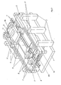
- Fig. 1 shows a machine structure with conveyor belts for clamping the workpieces
- Fig. 2 shows a machine structure for machining long workpieces
- the basic elements of the machine structure according to the invention consist of the base plate 1 with frame supports 2 and guide supports 3. Inside the guide supports 3, the conveyor chains or conveyor belts 4 with the workpiece 13 to be machined are arranged with its front and rear edges 13a, 13b.
- the tool carrier 9a, 9b runs above or below it on the tool carrier guides 7, 8.
- the stop boards 12 on the guides of the transport chains 4 serve for simultaneous machining of the workpiece 13 from above and below.
- the reference numeral 10 denotes the mirror surface of the guide device, while 11 schematically shows the energy supply.
- the basic elements of the machine structure according to the invention also consist of the base plate 1 with frame supports 2 and guide supports 3.
- the tool support guides 8 for the longitudinal guide (X-axis) are on the guide supports 3 above and below.
- the tool carrier guides 7 for the transverse guide (Y axis) are arranged between the longitudinal guides and carry the tool carriers 9a, 9b.
- the clamping devices 5 movable with them are mounted on the tool carriers 9a, 9b.
- the fixed clamping devices 6 are located on the guide supports 3 at both ends of the machine structure.
- Reference numeral 10 denotes the mirror surface of the guide device, while 11 schematically shows the energy supply.
- tensioning devices then advantageously allow the Processing of long, strip-shaped workpieces in such a way that the fixed or the longitudinally movable clamping devices 6, 5 hold the workpiece in the desired position for the tools to be used for the respective processing or, when the fixed clamping device 6 is open, transport it through it to the output-side clamping device or in the movable clamping device 5 of the upper tool carrier.
- the clamping devices 5, 6 are controlled so that at least one fixed clamping device holds the workpiece in relation to the machine structure and thus to the dimensional reference point of the electronic measuring device during machining in the X direction and clamps the movable clamping device 5 before the workpiece is transported before the fixed clamping devices 6 open, the workpiece is always held in a position known to the controller to the reference point.
- the tool carriers can be synchronized with the moving workpiece by actuating the movable clamping devices in the machining positions, as long as machining operations in Z and Y direction take place, or the strip is alternately tensioned and supported by the tensioning device of the one tool carrier and its travel in the X direction is measured while the other is working in the X, Y or Z direction.
Landscapes
- Engineering & Computer Science (AREA)
- Life Sciences & Earth Sciences (AREA)
- Mechanical Engineering (AREA)
- Wood Science & Technology (AREA)
- Forests & Forestry (AREA)
- Manufacturing & Machinery (AREA)
- Feeding Of Workpieces (AREA)
- Milling, Drilling, And Turning Of Wood (AREA)
Applications Claiming Priority (4)
| Application Number | Priority Date | Filing Date | Title |
|---|---|---|---|
| DE19803018760 DE3018760C2 (de) | 1980-05-16 | 1980-05-16 | Maschinenstruktur mit Führungsvorrichtung für numerisch gesteuerte Werkzeugträger |
| DE3018760 | 1980-05-16 | ||
| DE19803046766 DE3046766C2 (de) | 1980-12-12 | 1980-12-12 | Maschinenstruktur mit Führungsvorrichtung für numerisch gesteuerte Werkzeugträger an Bearbeitungsmaschinen für die Möbelindustrie |
| DE3046766 | 1980-12-12 |
Publications (3)
| Publication Number | Publication Date |
|---|---|
| EP0040317A2 true EP0040317A2 (fr) | 1981-11-25 |
| EP0040317A3 EP0040317A3 (en) | 1983-01-12 |
| EP0040317B1 EP0040317B1 (fr) | 1985-11-06 |
Family
ID=25785499
Family Applications (1)
| Application Number | Title | Priority Date | Filing Date |
|---|---|---|---|
| EP81102727A Expired EP0040317B1 (fr) | 1980-05-16 | 1981-04-10 | Structure d'une machine avec un dispositif de transport pour les porte-outils commandés numériquement dans des machines pour la fabrication de meubles |
Country Status (2)
| Country | Link |
|---|---|
| US (1) | US4449986A (fr) |
| EP (1) | EP0040317B1 (fr) |
Cited By (4)
| Publication number | Priority date | Publication date | Assignee | Title |
|---|---|---|---|---|
| EP0292712A3 (en) * | 1987-05-27 | 1990-05-09 | Priess, Horstmann & Co. Maschinenbau Gmbh & Co. Kg | Machine for working plate-like workpieces |
| EP0320624A3 (en) * | 1987-12-12 | 1990-08-16 | Urban Gmbh & Co. Maschinenbau Kg | Apparatus for removing burrs |
| AU639294B2 (en) * | 1990-02-07 | 1993-07-22 | Doorway Mfg. Co. | Method and apparatus for forming holes in wood board or the like |
| CN104526828A (zh) * | 2014-12-22 | 2015-04-22 | 佛山维尚家具制造有限公司 | 一种用于定制家具的板材自动加工设备 |
Families Citing this family (10)
| Publication number | Priority date | Publication date | Assignee | Title |
|---|---|---|---|---|
| DE3331844C1 (de) * | 1983-09-03 | 1991-09-26 | Rolf Dipl.-Ing. 5828 Ennepetal Peddinghaus | Vorrichtung zur Bearbeitung von Profilstaeben |
| JPH0646645B2 (ja) * | 1988-08-25 | 1994-06-15 | 株式会社東芝 | リードフレーム搬送装置 |
| US5653273A (en) * | 1995-08-14 | 1997-08-05 | Bach; Emin Nelson | Universal precision woodworking center |
| AU2002355296A1 (en) * | 2001-07-25 | 2003-02-17 | Lhr Technologies | Processor-controlled carving and multi-purpose shaping device |
| ITRM20040059A1 (it) * | 2004-02-04 | 2004-05-04 | Franco Saccone | Dispositivo per sagomatura, preferibilmente per la sagomatura di elementi sostanzialmente allungati. |
| KR101113252B1 (ko) * | 2004-05-12 | 2012-03-13 | 히노 지도샤 가부시키가이샤 | 물품의 조립대, 조립하는 방법 및 공정 표시장치 |
| US20070267103A1 (en) * | 2006-05-18 | 2007-11-22 | Unique Machine And Tool Co. | Woodworking machine |
| CN106862608A (zh) * | 2017-03-29 | 2017-06-20 | 成都中机盈科科技有限公司 | 一种提高工效的板材钻孔方法 |
| CN107008940A (zh) * | 2017-03-29 | 2017-08-04 | 成都中机盈科科技有限公司 | 一种提高工效的板材钻孔装置 |
| CN111015877B (zh) * | 2019-12-23 | 2022-11-22 | 重庆双羽家俱有限公司 | 异形线条加工用定位结构 |
Family Cites Families (6)
| Publication number | Priority date | Publication date | Assignee | Title |
|---|---|---|---|---|
| DE949007C (de) * | 1954-12-16 | 1956-09-13 | Schenck Gmbh Carl | Aufteilvorrichtung fuer einen aus lose geschuettetem Gut, beispielsweise aus Holzspaenen gebildeten endlosen Strang |
| US2978943A (en) * | 1956-09-17 | 1961-04-11 | Controls & Comm Co Inc | Photoelectric control circuit in combination with a toggle actuated cutter device |
| US3730634A (en) * | 1970-01-08 | 1973-05-01 | Gerber Garment Technology Inc | Apparatus for cutting and drilling sheet material |
| US3732474A (en) * | 1971-05-24 | 1973-05-08 | Square D Co | Positioning control system for a machine that performs work on a moving part |
| US3734153A (en) * | 1971-12-17 | 1973-05-22 | J Reed | Automatic cabinet making tool |
| GB1543381A (en) * | 1975-05-13 | 1979-04-04 | Pritelli Spa | Automatic plant for machining panels sheets or planks of wood or wood derivatives |
-
1981
- 1981-04-10 EP EP81102727A patent/EP0040317B1/fr not_active Expired
- 1981-05-14 US US06/263,566 patent/US4449986A/en not_active Expired - Fee Related
Cited By (5)
| Publication number | Priority date | Publication date | Assignee | Title |
|---|---|---|---|---|
| EP0292712A3 (en) * | 1987-05-27 | 1990-05-09 | Priess, Horstmann & Co. Maschinenbau Gmbh & Co. Kg | Machine for working plate-like workpieces |
| EP0320624A3 (en) * | 1987-12-12 | 1990-08-16 | Urban Gmbh & Co. Maschinenbau Kg | Apparatus for removing burrs |
| AU639294B2 (en) * | 1990-02-07 | 1993-07-22 | Doorway Mfg. Co. | Method and apparatus for forming holes in wood board or the like |
| CN104526828A (zh) * | 2014-12-22 | 2015-04-22 | 佛山维尚家具制造有限公司 | 一种用于定制家具的板材自动加工设备 |
| CN104526828B (zh) * | 2014-12-22 | 2017-01-18 | 佛山维尚家具制造有限公司 | 一种用于定制家具的板材自动加工设备 |
Also Published As
| Publication number | Publication date |
|---|---|
| EP0040317A3 (en) | 1983-01-12 |
| US4449986A (en) | 1984-05-22 |
| EP0040317B1 (fr) | 1985-11-06 |
Similar Documents
| Publication | Publication Date | Title |
|---|---|---|
| EP0184642B1 (fr) | Procédé pour produire des panneaux avec forages, de préférence en bois ou matière similaire, et installation pour exécuter ces procédés | |
| DE69226354T2 (de) | Mehrspindelmaschine zum bearbeiten von werkstücken durch von einander getrennte vorschub- und spanngeräte an jeder seite des werkzeugzusammenbaus | |
| EP0040317A2 (fr) | Structure d'une machine avec un dispositif de transport pour les porte-outils commandés numériquement dans des machines pour la fabrication de meubles | |
| EP1413395A1 (fr) | Machine-outil | |
| EP0130309B1 (fr) | Machines à travailler le bois | |
| DE2033026B2 (de) | NC-gesteueites Bearbeitungszentrum für durch Drehen von beiden Seiten her sowie durch Fräsen und/oder Bohren zu bearbeitende Werkstücke | |
| DE2409773B2 (de) | Kurvenlos programmgesteuerter mehrspindel-drehautomat | |
| DE102005061586A1 (de) | Drehbank, und Bearbeitungssystem mit einer Drehbank | |
| DE2636529A1 (de) | Saegemaschine fuer oberflaechenbeschichtete platten | |
| DE2704415A1 (de) | Bohrmaschine, insbesondere fuer die holzverarbeitung | |
| DE3147422C2 (de) | Holzbearbeitungsmaschine zum Zapfenschlagen und Längsprofilieren von Fensterhölzern | |
| EP3525997A1 (fr) | Procédé et dispositif de division de pièces en forme de plaques | |
| DE3305631C2 (fr) | ||
| DE3046766C2 (de) | Maschinenstruktur mit Führungsvorrichtung für numerisch gesteuerte Werkzeugträger an Bearbeitungsmaschinen für die Möbelindustrie | |
| DE102005020477A1 (de) | Bearbeitungseinheit an einer im Durchlauf arbeitenden Holzbearbeitungsmaschine | |
| DE3707230C2 (fr) | ||
| EP0362833A2 (fr) | Machine de travail du bois, de préférence une moulurière | |
| DE3018760C2 (de) | Maschinenstruktur mit Führungsvorrichtung für numerisch gesteuerte Werkzeugträger | |
| DE10047385C2 (de) | Verfahren und Vorrichtung zur Bearbeitung von fortlaufend bewegten Werkstücken | |
| DE3303162A1 (de) | Endprofiliermaschine | |
| DE2749546A1 (de) | Fensterhoelzer-bearbeitungsmaschine | |
| DE19826342A1 (de) | Plattenbearbeitungsmaschine | |
| EP0218001A1 (fr) | Machine à travailler des pièces à usiner en bois, plastique ou similaires, en particulier de boiseries pour fenêtres ou pièces à usiner similaires | |
| EP2998064A1 (fr) | Dispositif de traitement | |
| DE10356555A1 (de) | Vorrichtung zur Aufnahme von plattenförmigen Werkstücken |
Legal Events
| Date | Code | Title | Description |
|---|---|---|---|
| PUAI | Public reference made under article 153(3) epc to a published international application that has entered the european phase |
Free format text: ORIGINAL CODE: 0009012 |
|
| AK | Designated contracting states |
Designated state(s): FR GB IT SE |
|
| PUAL | Search report despatched |
Free format text: ORIGINAL CODE: 0009013 |
|
| RHK1 | Main classification (correction) |
Ipc: B23Q 7/00 |
|
| AK | Designated contracting states |
Designated state(s): FR GB IT SE |
|
| 17P | Request for examination filed |
Effective date: 19821210 |
|
| ITF | It: translation for a ep patent filed | ||
| GRAA | (expected) grant |
Free format text: ORIGINAL CODE: 0009210 |
|
| AK | Designated contracting states |
Designated state(s): FR GB IT SE |
|
| ET | Fr: translation filed | ||
| PLBE | No opposition filed within time limit |
Free format text: ORIGINAL CODE: 0009261 |
|
| STAA | Information on the status of an ep patent application or granted ep patent |
Free format text: STATUS: NO OPPOSITION FILED WITHIN TIME LIMIT |
|
| 26N | No opposition filed | ||
| ITTA | It: last paid annual fee | ||
| PGFP | Annual fee paid to national office [announced via postgrant information from national office to epo] |
Ref country code: SE Payment date: 19940323 Year of fee payment: 14 |
|
| PGFP | Annual fee paid to national office [announced via postgrant information from national office to epo] |
Ref country code: GB Payment date: 19940331 Year of fee payment: 14 |
|
| PGFP | Annual fee paid to national office [announced via postgrant information from national office to epo] |
Ref country code: FR Payment date: 19940429 Year of fee payment: 14 |
|
| EAL | Se: european patent in force in sweden |
Ref document number: 81102727.5 |
|
| PG25 | Lapsed in a contracting state [announced via postgrant information from national office to epo] |
Ref country code: GB Effective date: 19950410 |
|
| PG25 | Lapsed in a contracting state [announced via postgrant information from national office to epo] |
Ref country code: SE Effective date: 19950411 |
|
| GBPC | Gb: european patent ceased through non-payment of renewal fee |
Effective date: 19950410 |
|
| PG25 | Lapsed in a contracting state [announced via postgrant information from national office to epo] |
Ref country code: FR Effective date: 19951229 |
|
| EUG | Se: european patent has lapsed |
Ref document number: 81102727.5 |
|
| REG | Reference to a national code |
Ref country code: FR Ref legal event code: ST |