EP0040363B1 - Dispositif pour le filtrage adaptatif en temps réel de valeur de mesure de pression prise à l'aide d'un cathéter - Google Patents
Dispositif pour le filtrage adaptatif en temps réel de valeur de mesure de pression prise à l'aide d'un cathéter Download PDFInfo
- Publication number
- EP0040363B1 EP0040363B1 EP81103462A EP81103462A EP0040363B1 EP 0040363 B1 EP0040363 B1 EP 0040363B1 EP 81103462 A EP81103462 A EP 81103462A EP 81103462 A EP81103462 A EP 81103462A EP 0040363 B1 EP0040363 B1 EP 0040363B1
- Authority
- EP
- European Patent Office
- Prior art keywords
- filter
- pressure
- frequency
- output
- center frequency
- Prior art date
- Legal status (The legal status is an assumption and is not a legal conclusion. Google has not performed a legal analysis and makes no representation as to the accuracy of the status listed.)
- Expired
Links
- 230000004044 response Effects 0.000 claims description 25
- 230000005540 biological transmission Effects 0.000 claims description 14
- 239000012530 fluid Substances 0.000 claims description 5
- 239000003990 capacitor Substances 0.000 description 15
- 230000000694 effects Effects 0.000 description 8
- 238000000034 method Methods 0.000 description 8
- 238000010586 diagram Methods 0.000 description 7
- 238000001914 filtration Methods 0.000 description 3
- 230000006870 function Effects 0.000 description 3
- 238000009530 blood pressure measurement Methods 0.000 description 2
- 238000006243 chemical reaction Methods 0.000 description 2
- 230000000994 depressogenic effect Effects 0.000 description 2
- 230000002349 favourable effect Effects 0.000 description 2
- 238000011010 flushing procedure Methods 0.000 description 2
- 230000006978 adaptation Effects 0.000 description 1
- 230000003044 adaptive effect Effects 0.000 description 1
- 230000032683 aging Effects 0.000 description 1
- 230000015572 biosynthetic process Effects 0.000 description 1
- 238000001361 intraarterial administration Methods 0.000 description 1
- 230000009545 invasion Effects 0.000 description 1
- 238000005259 measurement Methods 0.000 description 1
- 230000000474 nursing effect Effects 0.000 description 1
- 230000035755 proliferation Effects 0.000 description 1
Images


Classifications
-
- H—ELECTRICITY
- H03—ELECTRONIC CIRCUITRY
- H03H—IMPEDANCE NETWORKS, e.g. RESONANT CIRCUITS; RESONATORS
- H03H21/00—Adaptive networks
- H03H21/0001—Analogue adaptive filters
-
- A—HUMAN NECESSITIES
- A61—MEDICAL OR VETERINARY SCIENCE; HYGIENE
- A61B—DIAGNOSIS; SURGERY; IDENTIFICATION
- A61B5/00—Measuring for diagnostic purposes; Identification of persons
- A61B5/02—Detecting, measuring or recording for evaluating the cardiovascular system, e.g. pulse, heart rate, blood pressure or blood flow
- A61B5/021—Measuring pressure in heart or blood vessels
- A61B5/0215—Measuring pressure in heart or blood vessels by means inserted into the body
Definitions
- the main object of the present invention is to provide an apparatus for compensating for the wide variations of resonance frequency, various transmission line lengths and system aging.
- the control circuit 50 comprises a start switch 51 which in the portrayed embodiments is a single pulsing switch which can be manually operated to start the compensation process.
- a latch 54 records the pulse from the start switch 51 and applies a signal to the control logic 55 which initiates the pressure step in the line and the switching over of the switch 31 from terminal 31 a and 31 b to the state shown in Fig. 4.
- the control logic also thereafter controls the operation of the tunable filter 40.
- the storing and reproducing circuit 60 is most advantageously carried out by a delta-modulator A/D converter circuit, because of the fact that it inherently provides for both A-D and D-A conversion as will be described.
- the delta-modulator A-D converter includes amplifier 61 which has the positive input thereof attached to the output of amplifier 22 and the output thereof attached to the D input of a D-type flip-flop 65.
- the Q-output of flip-flop 65 is fed back into the negative input of the amplifier 64 through an RC circuit comprising resistor R1 and capacitor C1.
- the flip-flop 65 is clocked by clock signal CLCK which originates from the divider 53 and the relative timing of signal CLCK is shown in Fig. 6.
- the output of amplifier 72 is fed back to the negative input thereof and also applied to the positive input of comparator amplifier 75. Further, the output of amplifier 72 is applied to the input of an analog switch 73 whose output is applied across capacitor C4 connected to ground and to the positive input of amplifier 74.
- the control input of analog switch 73 is controlled by timing signal SHFT which is shown in Fig. 6 and switch 73 is used to shift the voltage across C3 (V c3 ) to C4 and is described in more detail hereinafter.
- the output of amplifier 74 is fed back to the negative input thereof and is also applied to the negative input of comparator amplifier 75.
- the output of amplifier 75 is applied to one input of NAND-gate 76 whose other input is connected to timing signal STRB which is shown in Fig.
- the peak detector 70 is used both for the tuning of the center frequency and the timing of the notch depth and thus for purposes of explaining the operation thereof, it will only be explained with respect to the tuning of the center frequency.
- the binary counter 41a Upon the depression of switch 51, the binary counter 41a is reset at input R to its maximum value such that the D-A 42a provides a maximum voltage value to the coupler 43a such that the active filter is tuned to this maximum frequency, for example 100 Hz.
- the steps signal which has been stored is now reproduced periodically at the input of the active filter 44.
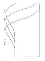
- the peak overshoot response for each successive adjustment of the center frequency is fed to the input of amplifier 71.
- This value is stored in capacitor C3 so that it can be compared to the last received peak overshoot value stored in C4.
- the initial peak overshoot value is shifted to capacitor C4 via analog switch 73, which is effected by the control signal SHFT.
- the capacitor C3 is discharged via analog switch 78 as controlled by timing signal DSCH.
Landscapes
- Health & Medical Sciences (AREA)
- Life Sciences & Earth Sciences (AREA)
- Cardiology (AREA)
- Heart & Thoracic Surgery (AREA)
- Molecular Biology (AREA)
- Physiology (AREA)
- Biophysics (AREA)
- Pathology (AREA)
- Engineering & Computer Science (AREA)
- Biomedical Technology (AREA)
- Vascular Medicine (AREA)
- Medical Informatics (AREA)
- Physics & Mathematics (AREA)
- Surgery (AREA)
- Animal Behavior & Ethology (AREA)
- General Health & Medical Sciences (AREA)
- Public Health (AREA)
- Veterinary Medicine (AREA)
- Measuring Pulse, Heart Rate, Blood Pressure Or Blood Flow (AREA)
- Measuring And Recording Apparatus For Diagnosis (AREA)
- Measuring Fluid Pressure (AREA)
- Arrangements For Transmission Of Measured Signals (AREA)
Claims (6)
Applications Claiming Priority (2)
| Application Number | Priority Date | Filing Date | Title |
|---|---|---|---|
| US06/150,014 US4325382A (en) | 1980-05-15 | 1980-05-15 | Process and apparatus for the real time adaptive filtering of catheter pressure measurements |
| US150014 | 1998-09-09 |
Publications (3)
| Publication Number | Publication Date |
|---|---|
| EP0040363A2 EP0040363A2 (fr) | 1981-11-25 |
| EP0040363A3 EP0040363A3 (en) | 1982-02-10 |
| EP0040363B1 true EP0040363B1 (fr) | 1985-11-27 |
Family
ID=22532748
Family Applications (1)
| Application Number | Title | Priority Date | Filing Date |
|---|---|---|---|
| EP81103462A Expired EP0040363B1 (fr) | 1980-05-15 | 1981-05-07 | Dispositif pour le filtrage adaptatif en temps réel de valeur de mesure de pression prise à l'aide d'un cathéter |
Country Status (5)
| Country | Link |
|---|---|
| US (1) | US4325382A (fr) |
| EP (1) | EP0040363B1 (fr) |
| JP (1) | JPS5717099A (fr) |
| CA (1) | CA1172702A (fr) |
| DE (1) | DE3173049D1 (fr) |
Cited By (1)
| Publication number | Priority date | Publication date | Assignee | Title |
|---|---|---|---|---|
| KR101249622B1 (ko) * | 2004-11-26 | 2013-04-01 | 콘티넨탈 테베스 아게 운트 코. 오하게 | 디스크 브레이크용 캘리퍼 |
Families Citing this family (23)
| Publication number | Priority date | Publication date | Assignee | Title |
|---|---|---|---|---|
| US4576180A (en) * | 1983-08-08 | 1986-03-18 | Taheri Syde A | Method and apparatus for monitoring leg blood pressure of an ambulatory patient |
| US4611601A (en) * | 1984-02-17 | 1986-09-16 | Transamerica Delaval Inc. | Disposable transducer systems |
| US4546775A (en) * | 1984-06-18 | 1985-10-15 | Critikon, Inc. | Detection of blood pressure complexes in automated vital signs monitors |
| US5193547A (en) * | 1984-07-16 | 1993-03-16 | Evans Ii George D | Universal connector means for transducer/monitor systems |
| US4705047A (en) * | 1985-09-30 | 1987-11-10 | Camino Laboratories, Inc. | Output circuit for physiological measuring instruments |
| US4926674A (en) * | 1988-11-03 | 1990-05-22 | Innovex Inc. | Self-zeroing pressure signal generator |
| JPH0714951U (ja) * | 1990-12-29 | 1995-03-14 | デルタ工業株式会社 | 空調シート |
| US5485741A (en) * | 1993-10-19 | 1996-01-23 | Medamicus, Inc. | Vacuum calibration method for an optical fiber pressure transducer |
| US6925328B2 (en) | 2000-04-20 | 2005-08-02 | Biophan Technologies, Inc. | MRI-compatible implantable device |
| US8527046B2 (en) | 2000-04-20 | 2013-09-03 | Medtronic, Inc. | MRI-compatible implantable device |
| DE10049734A1 (de) * | 2000-09-28 | 2002-04-11 | Medserv Gmbh | Verfahren zur Ermittlung, Überwachung und Aktualisierung von Korrekturdaten für flüssigkeitsgefüllte Übertragungssysteme |
| US20020116028A1 (en) * | 2001-02-20 | 2002-08-22 | Wilson Greatbatch | MRI-compatible pacemaker with pulse carrying photonic catheter providing VOO functionality |
| US6829509B1 (en) * | 2001-02-20 | 2004-12-07 | Biophan Technologies, Inc. | Electromagnetic interference immune tissue invasive system |
| US7054686B2 (en) * | 2001-08-30 | 2006-05-30 | Biophan Technologies, Inc. | Pulsewidth electrical stimulation |
| US6731979B2 (en) | 2001-08-30 | 2004-05-04 | Biophan Technologies Inc. | Pulse width cardiac pacing apparatus |
| WO2003037399A2 (fr) * | 2001-10-31 | 2003-05-08 | Biophan Technologies, Inc. | Logement de composant hermetique pour catheter photonique |
| US6968236B2 (en) * | 2002-01-28 | 2005-11-22 | Biophan Technologies, Inc. | Ceramic cardiac electrodes |
| US6711440B2 (en) | 2002-04-11 | 2004-03-23 | Biophan Technologies, Inc. | MRI-compatible medical device with passive generation of optical sensing signals |
| US6725092B2 (en) | 2002-04-25 | 2004-04-20 | Biophan Technologies, Inc. | Electromagnetic radiation immune medical assist device adapter |
| US6925322B2 (en) * | 2002-07-25 | 2005-08-02 | Biophan Technologies, Inc. | Optical MRI catheter system |
| TWI258123B (en) * | 2005-02-03 | 2006-07-11 | Lite On It Corp | Apparatus for positioning a clamper of a disc driver |
| US7738610B2 (en) * | 2005-08-31 | 2010-06-15 | Honeywell International Inc. | Method and apparatus for automatic alignment of notch filters |
| EP1769736A1 (fr) * | 2005-09-29 | 2007-04-04 | Siemens Aktiengesellschaft | Méthode et appareil d'élimination d'artefacts oscillatoires lors de mesures invasives de pression sanguine |
Family Cites Families (5)
| Publication number | Priority date | Publication date | Assignee | Title |
|---|---|---|---|---|
| US2558190A (en) * | 1949-08-25 | 1951-06-26 | Sanborn Company | Electromanometer |
| US3714588A (en) * | 1970-10-13 | 1973-01-30 | Nasa | Self tuning bandpass filter |
| NL7313028A (nl) * | 1973-09-21 | 1975-03-25 | Tno | Werkwijze en inrichting voor het onderzoeken van de werking van een katheter-manometersysteem. |
| US3889108A (en) * | 1974-07-25 | 1975-06-10 | Us Navy | Adaptive low pass filter |
| US4232373A (en) * | 1978-04-14 | 1980-11-04 | Regents For Education Of The State Of Rhode Island | Compensation of fluidic transducers |
-
1980
- 1980-05-15 US US06/150,014 patent/US4325382A/en not_active Expired - Lifetime
-
1981
- 1981-04-30 CA CA000376581A patent/CA1172702A/fr not_active Expired
- 1981-05-07 EP EP81103462A patent/EP0040363B1/fr not_active Expired
- 1981-05-07 DE DE8181103462T patent/DE3173049D1/de not_active Expired
- 1981-05-15 JP JP7241781A patent/JPS5717099A/ja active Granted
Cited By (1)
| Publication number | Priority date | Publication date | Assignee | Title |
|---|---|---|---|---|
| KR101249622B1 (ko) * | 2004-11-26 | 2013-04-01 | 콘티넨탈 테베스 아게 운트 코. 오하게 | 디스크 브레이크용 캘리퍼 |
Also Published As
| Publication number | Publication date |
|---|---|
| EP0040363A2 (fr) | 1981-11-25 |
| DE3173049D1 (en) | 1986-01-09 |
| CA1172702A (fr) | 1984-08-14 |
| EP0040363A3 (en) | 1982-02-10 |
| JPS5717099A (en) | 1982-01-28 |
| US4325382A (en) | 1982-04-20 |
| JPH0145677B2 (fr) | 1989-10-04 |
Similar Documents
| Publication | Publication Date | Title |
|---|---|---|
| US4325382A (en) | Process and apparatus for the real time adaptive filtering of catheter pressure measurements | |
| US4953117A (en) | Method and apparatus for converting sampling frequencies | |
| US3968427A (en) | Group delay measurement apparatus and method | |
| US4279005A (en) | Method and system for automatically providing flat frequency response to audio signals recorded on magnetic tapes | |
| EP0511295A1 (fr) | Procede et appareil de reglage de la modulation de signaux numeriques dans des transmissions a modulation de frequence | |
| US12275635B2 (en) | System and method for fast mode change of a digital microphone using digital cross-talk compensation | |
| US6112125A (en) | Self-tuning method and apparatus for continuous-time filters | |
| US4843390A (en) | Oversampled A/D converter having digital error correction | |
| US5349352A (en) | Analog-to-digital converter having high AC line noise rejection and insensitive to AC line frequency variations | |
| CA1152578A (fr) | filtre eliminateur de bruits coherents | |
| US4649335A (en) | Equipment for locating a signal reflection point in a transmission line | |
| US6111532A (en) | Waveform shaper and sigma-delta D/A converter | |
| US4253155A (en) | Self-compensating measurement system | |
| JPS63199537A (ja) | クロック信号同期装置 | |
| US4367437A (en) | Reference voltage generator | |
| US4417310A (en) | Apparatus for measuring distortion factor | |
| US5151668A (en) | FM modulator for compensating modulation characteristics on each channel | |
| US4394743A (en) | Tone generation method and apparatus using stored reference calibration coefficients | |
| US7636386B2 (en) | Method of continuously calibrating the gain for a multi-path angle modulator | |
| JPH077375A (ja) | 伝送線路の減衰補償方式 | |
| US7146518B2 (en) | Filter circuit with automatic adjustment of cutoff frequency via average signal values | |
| JPS5847331A (ja) | 信号発生器 | |
| JP3125441B2 (ja) | 信号処理装置 | |
| JP3263126B2 (ja) | 超音波診断装置 | |
| JPH0590954A (ja) | 温度補償型発振器 |
Legal Events
| Date | Code | Title | Description |
|---|---|---|---|
| PUAI | Public reference made under article 153(3) epc to a published international application that has entered the european phase |
Free format text: ORIGINAL CODE: 0009012 |
|
| AK | Designated contracting states |
Designated state(s): DE FR GB IT |
|
| PUAL | Search report despatched |
Free format text: ORIGINAL CODE: 0009013 |
|
| AK | Designated contracting states |
Designated state(s): DE FR GB IT |
|
| 17P | Request for examination filed |
Effective date: 19820721 |
|
| RAP1 | Party data changed (applicant data changed or rights of an application transferred) |
Owner name: MEMORIAL HOSPITAL FOR CANCER AND ALLIED DISEASES |
|
| ITF | It: translation for a ep patent filed | ||
| GRAA | (expected) grant |
Free format text: ORIGINAL CODE: 0009210 |
|
| AK | Designated contracting states |
Designated state(s): DE FR GB IT |
|
| REF | Corresponds to: |
Ref document number: 3173049 Country of ref document: DE Date of ref document: 19860109 |
|
| ET | Fr: translation filed | ||
| PLBE | No opposition filed within time limit |
Free format text: ORIGINAL CODE: 0009261 |
|
| STAA | Information on the status of an ep patent application or granted ep patent |
Free format text: STATUS: NO OPPOSITION FILED WITHIN TIME LIMIT |
|
| 26N | No opposition filed | ||
| PGFP | Annual fee paid to national office [announced via postgrant information from national office to epo] |
Ref country code: FR Payment date: 19900410 Year of fee payment: 10 |
|
| PGFP | Annual fee paid to national office [announced via postgrant information from national office to epo] |
Ref country code: GB Payment date: 19900412 Year of fee payment: 10 |
|
| PGFP | Annual fee paid to national office [announced via postgrant information from national office to epo] |
Ref country code: DE Payment date: 19900427 Year of fee payment: 10 |
|
| ITTA | It: last paid annual fee | ||
| PG25 | Lapsed in a contracting state [announced via postgrant information from national office to epo] |
Ref country code: GB Effective date: 19910507 |
|
| GBPC | Gb: european patent ceased through non-payment of renewal fee | ||
| PG25 | Lapsed in a contracting state [announced via postgrant information from national office to epo] |
Ref country code: FR Effective date: 19920131 |
|
| PG25 | Lapsed in a contracting state [announced via postgrant information from national office to epo] |
Ref country code: DE Effective date: 19920303 |
|
| REG | Reference to a national code |
Ref country code: FR Ref legal event code: ST |