EP0040689A1 - Dispositif de réglage et de préréglage d'opérations d'enclenchement et de déclenchement et de gammes de condition - Google Patents
Dispositif de réglage et de préréglage d'opérations d'enclenchement et de déclenchement et de gammes de condition Download PDFInfo
- Publication number
- EP0040689A1 EP0040689A1 EP81102705A EP81102705A EP0040689A1 EP 0040689 A1 EP0040689 A1 EP 0040689A1 EP 81102705 A EP81102705 A EP 81102705A EP 81102705 A EP81102705 A EP 81102705A EP 0040689 A1 EP0040689 A1 EP 0040689A1
- Authority
- EP
- European Patent Office
- Prior art keywords
- arrangement according
- dcu
- control units
- decentralized control
- unit
- Prior art date
- Legal status (The legal status is an assumption and is not a legal conclusion. Google has not performed a legal analysis and makes no representation as to the accuracy of the status listed.)
- Withdrawn
Links
Images

Classifications
-
- G—PHYSICS
- G05—CONTROLLING; REGULATING
- G05B—CONTROL OR REGULATING SYSTEMS IN GENERAL; FUNCTIONAL ELEMENTS OF SUCH SYSTEMS; MONITORING OR TESTING ARRANGEMENTS FOR SUCH SYSTEMS OR ELEMENTS
- G05B19/00—Program-control systems
- G05B19/02—Program-control systems electric
- G05B19/04—Program control other than numerical control, i.e. in sequence controllers or logic controllers
- G05B19/042—Program control other than numerical control, i.e. in sequence controllers or logic controllers using digital processors
- G05B19/0423—Input/output
-
- G—PHYSICS
- G05—CONTROLLING; REGULATING
- G05D—SYSTEMS FOR CONTROLLING OR REGULATING NON-ELECTRIC VARIABLES
- G05D23/00—Control of temperature
- G05D23/19—Control of temperature characterised by the use of electric means
- G05D23/1917—Control of temperature characterised by the use of electric means using digital means
-
- H—ELECTRICITY
- H02—GENERATION; CONVERSION OR DISTRIBUTION OF ELECTRIC POWER
- H02J—ELECTRIC POWER NETWORKS; CIRCUIT ARRANGEMENTS OR SYSTEMS FOR SUPPLYING OR DISTRIBUTING ELECTRIC POWER; SYSTEMS FOR STORING ELECTRIC ENERGY
- H02J13/00—Circuit arrangements for providing remote monitoring or remote control of equipment in a power distribution network
- H02J13/13—Circuit arrangements for providing remote monitoring or remote control of equipment in a power distribution network characterised by the transmission of data to equipment in the power network
- H02J13/1311—Circuit arrangements for providing remote monitoring or remote control of equipment in a power distribution network characterised by the transmission of data to equipment in the power network using the power network as support for the transmission
-
- H—ELECTRICITY
- H02—GENERATION; CONVERSION OR DISTRIBUTION OF ELECTRIC POWER
- H02J—ELECTRIC POWER NETWORKS; CIRCUIT ARRANGEMENTS OR SYSTEMS FOR SUPPLYING OR DISTRIBUTING ELECTRIC POWER; SYSTEMS FOR STORING ELECTRIC ENERGY
- H02J13/00—Circuit arrangements for providing remote monitoring or remote control of equipment in a power distribution network
- H02J13/14—Circuit arrangements for providing remote monitoring or remote control of equipment in a power distribution network the power network being locally controlled, e.g. home energy management systems [HEMS]
-
- H—ELECTRICITY
- H02—GENERATION; CONVERSION OR DISTRIBUTION OF ELECTRIC POWER
- H02J—ELECTRIC POWER NETWORKS; CIRCUIT ARRANGEMENTS OR SYSTEMS FOR SUPPLYING OR DISTRIBUTING ELECTRIC POWER; SYSTEMS FOR STORING ELECTRIC ENERGY
- H02J2105/00—Networks for supplying or distributing electric power characterised by their spatial reach or by the load
- H02J2105/10—Local stationary networks having a local or delimited stationary reach
- H02J2105/12—Local stationary networks having a local or delimited stationary reach supplying households or buildings
-
- Y—GENERAL TAGGING OF NEW TECHNOLOGICAL DEVELOPMENTS; GENERAL TAGGING OF CROSS-SECTIONAL TECHNOLOGIES SPANNING OVER SEVERAL SECTIONS OF THE IPC; TECHNICAL SUBJECTS COVERED BY FORMER USPC CROSS-REFERENCE ART COLLECTIONS [XRACs] AND DIGESTS
- Y02—TECHNOLOGIES OR APPLICATIONS FOR MITIGATION OR ADAPTATION AGAINST CLIMATE CHANGE
- Y02B—CLIMATE CHANGE MITIGATION TECHNOLOGIES RELATED TO BUILDINGS, e.g. HOUSING, HOUSE APPLIANCES OR RELATED END-USER APPLICATIONS
- Y02B90/00—Enabling technologies or technologies with a potential or indirect contribution to GHG emissions mitigation
- Y02B90/20—Smart grids as enabling technology in buildings sector
-
- Y—GENERAL TAGGING OF NEW TECHNOLOGICAL DEVELOPMENTS; GENERAL TAGGING OF CROSS-SECTIONAL TECHNOLOGIES SPANNING OVER SEVERAL SECTIONS OF THE IPC; TECHNICAL SUBJECTS COVERED BY FORMER USPC CROSS-REFERENCE ART COLLECTIONS [XRACs] AND DIGESTS
- Y04—INFORMATION OR COMMUNICATION TECHNOLOGIES HAVING AN IMPACT ON OTHER TECHNOLOGY AREAS
- Y04S—SYSTEMS INTEGRATING TECHNOLOGIES RELATED TO POWER NETWORK OPERATION, COMMUNICATION OR INFORMATION TECHNOLOGIES FOR IMPROVING THE ELECTRICAL POWER GENERATION, TRANSMISSION, DISTRIBUTION, MANAGEMENT OR USAGE, i.e. SMART GRIDS
- Y04S20/00—Management or operation of end-user stationary applications or the last stages of power distribution; Controlling, monitoring or operating thereof
-
- Y—GENERAL TAGGING OF NEW TECHNOLOGICAL DEVELOPMENTS; GENERAL TAGGING OF CROSS-SECTIONAL TECHNOLOGIES SPANNING OVER SEVERAL SECTIONS OF THE IPC; TECHNICAL SUBJECTS COVERED BY FORMER USPC CROSS-REFERENCE ART COLLECTIONS [XRACs] AND DIGESTS
- Y04—INFORMATION OR COMMUNICATION TECHNOLOGIES HAVING AN IMPACT ON OTHER TECHNOLOGY AREAS
- Y04S—SYSTEMS INTEGRATING TECHNOLOGIES RELATED TO POWER NETWORK OPERATION, COMMUNICATION OR INFORMATION TECHNOLOGIES FOR IMPROVING THE ELECTRICAL POWER GENERATION, TRANSMISSION, DISTRIBUTION, MANAGEMENT OR USAGE, i.e. SMART GRIDS
- Y04S40/00—Systems for electrical power generation, transmission, distribution or end-user application management characterised by the use of communication or information technologies, or communication or information technology specific aspects supporting them
- Y04S40/12—Systems for electrical power generation, transmission, distribution or end-user application management characterised by the use of communication or information technologies, or communication or information technology specific aspects supporting them characterised by data transport means between the monitoring, controlling or managing units and monitored, controlled or operated electrical equipment
- Y04S40/121—Systems for electrical power generation, transmission, distribution or end-user application management characterised by the use of communication or information technologies, or communication or information technology specific aspects supporting them characterised by data transport means between the monitoring, controlling or managing units and monitored, controlled or operated electrical equipment using the power network as support for the transmission
Definitions
- the invention relates to an arrangement for setting and presetting switch-on and switch-off processes and status areas in different rooms of buildings.
- Such arrangements are light switches in the simplest form, which enable a lamp to be switched on or off in another room via a line.
- the object of the invention is to provide an arrangement which enables the setting and presetting of switch-on and switch-off processes and of state areas in different rooms of buildings from a room which avoids the disadvantages of the arrangements described above, can be produced at low cost is and can be produced without great effort even after completion of the building.
- this arrangement according to the invention therefore, no separate lines have to be laid from the room from which remote control is to take place to the decentralized control units. On the one hand, this saves a lot of material. On the other hand, this arrangement according to the invention is also particularly cost-effective because it can also be retrofitted into any building or simply used.
- Another very significant advantage of the present invention is that the user does not have to determine where he wants his central control and monitoring unit to be. Even if the entire arrangement or system is already installed, he can convert it in a very simple way. Not only when he moves the entire apartment around, but also at any time he has this opportunity. For this purpose, he only has to pull the plug of the central control and monitor unit out of the socket, take this control and monitor unit to another room, for example in the evening in the bedroom, and then put the plug of this unit back into the next socket.
- the invention also has the advantage that it can be used both in an enclosed space and in single and multi-family houses, as well as in office or factory buildings of any size.
- the more decentralized control units for triggering switching or control steps are to be remotely controlled from the central and the farther away these decentralized control units are arranged from the central, the more the advantage of the material savings and the saving on workload achieved by the invention comes into play.
- the decentralized control units can be connected to switches of electrical devices.
- switches of electrical devices can be lamps, but it can also be, for example, a switch A coffee machine, a radio or an oven.
- motors are provided which can be controlled by the decentralized control units. These motors can be connected to actuators.
- This development of the invention enables its application to the remote control of almost any adjustable objects in the house, e.g. of shutters, blinds or the like.
- the devices to be controlled can either be controlled from one end position to the other end position, or, with the help of the actuators, also into the desired intermediate positions.
- the central control and motor unit, and therefore also the decentralized control units expediently have network interfaces. These interfaces serve to separate the low-voltage electronics from the voltage and at the same time to transmit the signals from the electronics to the network and vice versa to transmit the signals from the network to the central control unit or to the decentralized control units.
- the decentralized control units are connected directly to the actuators. This direct connection can be made via a normal line.
- the heating of the building technology is always a particular problem.
- the heating is controlled by a central thermostat in such a way that the heating water or the heating air in the burner is always heated in such a way that the individual rooms of the house can have certain minimum or maximum temperatures.
- this central control will be set to maximum temperature in order to provide the required heating energy in any desired room at short notice if required.
- Mechanical or thermostatic valves are attached to the radiators in the individual rooms, which must be set individually by the user if he wants to heat the room. It should be noted that in the case of purely mechanical valves, the user generally only sets "open” or "closed”, whereas an approximate temperature range could be set for thermostatic valves.
- the decentralized control units are communicatively connected to sensors.
- These sensors can be temperature sensors which are arranged at a distance from the decentralized control units or which are arranged together with a decentralized control unit in a single structural unit.
- a plurality of temperature sensors can also be arranged in a room, all of which communicate with a decentralized control unit in this room.
- this development of the invention is also in no way limited to the application of heating regulation.
- temperature sensors other sensors can also be provided, for example smoke sensors, which trigger an alarm signal at the central control and monitoring unit if the amount of smoke in a room exceeds a certain threshold value.
- smoke sensors which trigger an alarm signal at the central control and monitoring unit if the amount of smoke in a room exceeds a certain threshold value.
- This development of the invention can thus be used simultaneously as a fire alarm, for example.
- This system can also be used as a fire alarm with alarm signals in the control center.
- the sprinkler system can be put into operation exactly in the desired rooms and at the desired locations.
- the central control and monitor unit comprises a microprocessor and an associated logic circuit.
- the central control and monitor unit comprises a keypad for data entry and a visual display.
- This development of the invention enables the input of desired setpoints into the device, the visual display simultaneously enabling control over the correctness of the input made.
- the states measured by the sensors in the various rooms can also be made visible on the field of view. With the aid of this embodiment, the programming of the entire arrangement is also made possible.
- the control and monitor unit can expediently contain an acoustic alarm unit.
- it also contains an electronic clock, which can either be powered by a battery or can have a battery-powered buffer circuit. With the help of this clock, desired states, which are entered in advance via the keypad, can be established at the desired time. If the watch is either powered by a battery or has a buffer circuit, it continues to measure the time even when the central control unit is disconnected from the mains, e.g. because it should be carried to another room.
- the decentralized control units can also each comprise a microprocessor and an associated logic. This makes the entire arrangement applicable for the control and regulation of the entire building technology. In the case of heating alone, this arrangement according to the invention can save 25 to 50% of the energy required otherwise.
- Said actuating devices can be connected to rotary valves, slide valves, dampers and closing or other mechanical devices, e.g. with motors for operating roller shutters or blinds.
- the display of the heating costs per hour at the current heating output can be shown on the display.
- a sensor connected to a decentralized control unit can advantageously be provided for sensing the amount of fuel flowing through the fuel line per unit of time. Because of the flow rate and thus the flow rate per time, the current consumption in monetary value per unit of time can easily be calculated from the price of the fuel per amount and displayed on the central control and monitoring device.
- the invention also allows the respective over longer time intervals, e.g. save fuel quantities used during a week and display this value, if desired multiplied by the price per quantity, on the central control and monitoring device.
- this arrangement is programmable so that it learns independently how heating costs are saved. Starting from the fact that the temperature of the heating water initially has a certain difference to the outside temperature, it can initially be during a period of e.g. 3 days of fuel consumption measured and this value saved. The temperature gradient between the heating water temperature and the temperature outside the building can then be increased, and after 3 days the value of the amount of fuel used can be compared with the value of the amount of fuel that was used in the previous time interval.
- any suitable algorithms can be specified, which can then be carried out automatically by the arrangement according to the invention with the success that the energy consumption is automatically minimized.
- the mixer of the central heating system can also do so with the present invention be regulated so that the energy requirement is minimized.
- a scanner can be provided which continuously polls the states of the various sensors and / or the positions of the various actuating devices. This ensures constant monitoring.
- Non-volatile memories are advantageously provided. These ensure that the programmed and measured values are not lost, but remain saved even if the power supply to the house network fails.
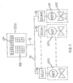
- FIG. 1 shows a central control and monitoring unit CCU, which contains a keypad KB and a visual display DP.
- This central control and monitoring unit CCU is connected via a line 12 to the power grid 14 of the building. This connection is done in the usual way with the help of a line and a plug that is plugged into a power socket.
- This figure also shows n decentralized control units DCU 1 to DCU n, each of which is connected to the power supply system of the building via a line 16.
- Each of these decentralized control units DCU is connected via a line 18 to a motor MOT, which in turn is connected to one of the valves PU 1,... PU n.
- the valves are radiator valves.
- a decentralized control unit DCU (MX) is also provided, which is connected to a motor MOT X, which in turn is connected to a mixing valve MX.
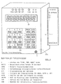
- FIG. 2 various components of the central control and monitoring unit CCU are shown in the shield delimited by dashed lines 20.
- a microcomputer MC is shown in the middle of this field, which essentially consists of a microprocessor MP and a read-only memory (ROM). This microcomputer MC communicates with an electrically changeable read-only memory or read-only memory EAROM.
- An electronic clock CL is also connected to the microprocessor MP.
- a scanner SC which communicates both with a visual display DP and with a keypad KB.
- This scanner can constantly display the DP and the KB via the keypad scan the entered values and send them to the Mikrocom forward computer.
- a modem M is provided in the left area of the field 20.
- the central control and monitoring unit CCU is connected to the mains 12 of the house via this modem M.
- the decentralized control units DCU control electric motors, which can adjust micro valves for heating radiators. All electronics are integrated in the DCU. This electronics includes the address decoder, the temperature sensor and the transmission circuit. For safety reasons, the motor and electronics work with a protective low voltage (below 42 V), which is obtained from the AC network via the network interfaces. The electric motor is able to move the valve not only to the "open” and “closed” end positions, but also to several intermediate positions, i.e. to bring different opening positions.
- the temperature sensor registers the room temperature and reports it to the DCU. This in turn opens or closes, completely or partially, with the microvalve to regulate the set temperature.
- the data transmission takes place via the lines of the power network (110/220 V; 50/60 Hz) by means of frequency-modulated signals.
- the data traffic is set up by the central control and monitoring unit CCU, and the addressed decentralized control unit DCU reports current parameters of your room (e.g. temperature, smoke present, etc.).
- the central control and monitor unit continuously polls all decentralized control units DCU, compares the programmed data with the actual data and controls the decentralized control unit DCU accordingly.
- the decentralized control units are only connected to a socket in the main power network.
- the decentralized control units can either control water valves for hot water central heating or air slides for heating with warm air or air conditioning systems. This does not change their function.
- the decentralized control units DCU can control several of them, one and the same device, but they can also control several external devices at the same time. This option is technically implemented by an "open collector" circuit. Alarm contacts or roller shutter actuation contacts of doors or windows can be connected to these two inputs / outputs. Control system can be expanded to house alarm and locking system without further significant costs. Such addressed window contacts can also be used to save energy. If there is ventilation in a room and the windows are accidentally left open for a long time, the room temperature drops very quickly when the outside temperature is lower. In most heating programs, after such a temperature drop in a room, with a certain time delay due to the measured low temperature, the heating valve is opened and the heating in this room is switched on.
- a further component can be connected to the thermal control arrangement according to the invention.
- This regulates the mixer which regulates the water flow temperature of the heating burner depending on the temperature gradients of the individual rooms in relation to the outside temperature.
- the construction of the mixer MX corresponds to that of the decentralized control unit DCU, however with the difference that a 4-way rotary valve is provided as the valve.
- the temperature sensor controls the water flow temperature.
- the described thermal control system is only one exemplary embodiment of the various possible uses of the arrangement according to the invention.
Landscapes
- Engineering & Computer Science (AREA)
- Physics & Mathematics (AREA)
- General Physics & Mathematics (AREA)
- Automation & Control Theory (AREA)
- Power Engineering (AREA)
- Air Conditioning Control Device (AREA)
- Selective Calling Equipment (AREA)
Applications Claiming Priority (2)
| Application Number | Priority Date | Filing Date | Title |
|---|---|---|---|
| DE3020099 | 1980-05-27 | ||
| DE19803020099 DE3020099A1 (de) | 1980-05-27 | 1980-05-27 | Anordnung zur einstellung und voreinstellung von ein- und ausschaltvorgaengen und von zustandsbereichen |
Publications (1)
| Publication Number | Publication Date |
|---|---|
| EP0040689A1 true EP0040689A1 (fr) | 1981-12-02 |
Family
ID=6103351
Family Applications (1)
| Application Number | Title | Priority Date | Filing Date |
|---|---|---|---|
| EP81102705A Withdrawn EP0040689A1 (fr) | 1980-05-27 | 1981-04-09 | Dispositif de réglage et de préréglage d'opérations d'enclenchement et de déclenchement et de gammes de condition |
Country Status (2)
| Country | Link |
|---|---|
| EP (1) | EP0040689A1 (fr) |
| DE (1) | DE3020099A1 (fr) |
Cited By (9)
| Publication number | Priority date | Publication date | Assignee | Title |
|---|---|---|---|---|
| FR2521320A1 (fr) * | 1982-02-09 | 1983-08-12 | Garret Roger | Dispositif et procede de programmation de regulation et d'autocontrole notamment pour le chauffage |
| FR2536877A1 (fr) * | 1982-11-29 | 1984-06-01 | Encinas Victor | Procede et dispositif de programmation, de regulation, de controle d'economie du fonctionnement d'une installation de chauffage |
| WO1985000064A1 (fr) * | 1983-06-17 | 1985-01-03 | Johnson Service Company | Controleur de condition de zone et son procede d'utilisation |
| GB2174560A (en) * | 1985-04-26 | 1986-11-05 | David William Farley | Electrical supply system |
| FR2587512A1 (fr) * | 1985-09-19 | 1987-03-20 | Kleist Cornelis | Systeme de controle et de regulation pour des dispositifs utilisant de l'energie |
| WO1987002539A1 (fr) * | 1985-10-09 | 1987-04-23 | Kivelae Erkki | Dispositif de commande et de commutation pour chauffage electrique |
| EP0223663A1 (fr) * | 1985-10-15 | 1987-05-27 | Electricite De France | Système de commande sélective d'une série de terminaux périphériques par un dispositif de commande central |
| WO1999043068A1 (fr) * | 1998-02-20 | 1999-08-26 | Merloni Elettrodomestici S.P.A. | Systeme, dispositif et procede de suivi d'une pluralite d'ustensiles electriques, notamment d'appareils electromenagers |
| AT412691B (de) * | 1999-09-17 | 2005-05-25 | Braun Werner | System zur steuerung von räumlich verteilten elektrischen verbrauchern in gebäuden |
Families Citing this family (2)
| Publication number | Priority date | Publication date | Assignee | Title |
|---|---|---|---|---|
| DE3234150C2 (de) * | 1982-09-15 | 1984-09-13 | Samson Ag, 6000 Frankfurt | Einrichtung zum Übertragen von Daten bei einem Sammelheizungssystem |
| DE9312599U1 (de) * | 1993-08-23 | 1993-10-21 | Licentia Patent-Verwaltungs-Gmbh, 60596 Frankfurt | Regler für eine Heizungsanlage |
Citations (4)
| Publication number | Priority date | Publication date | Assignee | Title |
|---|---|---|---|---|
| DE2047725A1 (de) * | 1969-10-08 | 1971-04-22 | Honeywell Inc | System zur zentralen Steuerung und Überwachung |
| DE2819032A1 (de) * | 1978-04-29 | 1979-11-08 | Walther Bueromasch Gmbh | Verfahren und vorrichtungsanordnung eines elektronisch gesteuerten heizkreisthermostaten |
| DE2832942A1 (de) * | 1978-07-27 | 1980-02-07 | Bbc Brown Boveri & Cie | Hausleitsystem |
| EP0019344A1 (fr) * | 1979-05-17 | 1980-11-26 | Bretec Benelux B.V. | Procédé et dispositif de régulation de la température à l'intérieur d'un espace fermé |
-
1980
- 1980-05-27 DE DE19803020099 patent/DE3020099A1/de not_active Withdrawn
-
1981
- 1981-04-09 EP EP81102705A patent/EP0040689A1/fr not_active Withdrawn
Patent Citations (4)
| Publication number | Priority date | Publication date | Assignee | Title |
|---|---|---|---|---|
| DE2047725A1 (de) * | 1969-10-08 | 1971-04-22 | Honeywell Inc | System zur zentralen Steuerung und Überwachung |
| DE2819032A1 (de) * | 1978-04-29 | 1979-11-08 | Walther Bueromasch Gmbh | Verfahren und vorrichtungsanordnung eines elektronisch gesteuerten heizkreisthermostaten |
| DE2832942A1 (de) * | 1978-07-27 | 1980-02-07 | Bbc Brown Boveri & Cie | Hausleitsystem |
| EP0019344A1 (fr) * | 1979-05-17 | 1980-11-26 | Bretec Benelux B.V. | Procédé et dispositif de régulation de la température à l'intérieur d'un espace fermé |
Cited By (12)
| Publication number | Priority date | Publication date | Assignee | Title |
|---|---|---|---|---|
| FR2521320A1 (fr) * | 1982-02-09 | 1983-08-12 | Garret Roger | Dispositif et procede de programmation de regulation et d'autocontrole notamment pour le chauffage |
| FR2536877A1 (fr) * | 1982-11-29 | 1984-06-01 | Encinas Victor | Procede et dispositif de programmation, de regulation, de controle d'economie du fonctionnement d'une installation de chauffage |
| WO1985000064A1 (fr) * | 1983-06-17 | 1985-01-03 | Johnson Service Company | Controleur de condition de zone et son procede d'utilisation |
| GB2149941A (en) * | 1983-06-17 | 1985-06-19 | Johnson Service Co | Zone condition controller and method of using same |
| GB2174560A (en) * | 1985-04-26 | 1986-11-05 | David William Farley | Electrical supply system |
| GB2174560B (en) * | 1985-04-26 | 1989-06-28 | David William Farley | Electrical supply system for a central heating system |
| FR2587512A1 (fr) * | 1985-09-19 | 1987-03-20 | Kleist Cornelis | Systeme de controle et de regulation pour des dispositifs utilisant de l'energie |
| WO1987002539A1 (fr) * | 1985-10-09 | 1987-04-23 | Kivelae Erkki | Dispositif de commande et de commutation pour chauffage electrique |
| US4908498A (en) * | 1985-10-09 | 1990-03-13 | Kivelae Erkki | Control for delivery of power to heating elements |
| EP0223663A1 (fr) * | 1985-10-15 | 1987-05-27 | Electricite De France | Système de commande sélective d'une série de terminaux périphériques par un dispositif de commande central |
| WO1999043068A1 (fr) * | 1998-02-20 | 1999-08-26 | Merloni Elettrodomestici S.P.A. | Systeme, dispositif et procede de suivi d'une pluralite d'ustensiles electriques, notamment d'appareils electromenagers |
| AT412691B (de) * | 1999-09-17 | 2005-05-25 | Braun Werner | System zur steuerung von räumlich verteilten elektrischen verbrauchern in gebäuden |
Also Published As
| Publication number | Publication date |
|---|---|
| DE3020099A1 (de) | 1981-12-03 |
Similar Documents
| Publication | Publication Date | Title |
|---|---|---|
| DE69300687T2 (de) | Regeleinrichtung für Wohnungs-Heizung und -Klimatisierung. | |
| DE69416353T2 (de) | Temperaturregelsystem mit einer Steuerungszentrale für Thermostaten | |
| DE4237845A1 (fr) | ||
| EP0208256B1 (fr) | Dispositif de régulation de la température d'un local | |
| EP0040689A1 (fr) | Dispositif de réglage et de préréglage d'opérations d'enclenchement et de déclenchement et de gammes de condition | |
| DE102014102275B4 (de) | Verfahren zur Regelung einer Heizungs- und/oder Klimaanlage und Heizungs- und/oder Klimaanlage hierzu | |
| DE102007037694A1 (de) | Fernsteuerung für ein Klimagerät | |
| EP0617238B1 (fr) | Dispositif de chauffage et son contrÔle | |
| DE2636195A1 (de) | Anlage zum beheizen eines gebaeudes | |
| EP0982642B1 (fr) | Procédé de commande d'installations électriques dans des bâtiments et dispositif de commande pour la commande d'installations électriques dans des bâtiments | |
| DE202011110079U1 (de) | System zur Ansteuerung eines Thermostatventils | |
| EP0805311A2 (fr) | Dispositif de réglage pour installation de chauffage | |
| DE3147085A1 (de) | Vorrichtung zur energieeinsparung, insbesondere in beheizten oder klimatisierten raeumen | |
| CH672852A5 (fr) | ||
| DE3222213A1 (de) | Einrichtung zur temperatursteuerung der einzelraeume eines gebaeudes | |
| EP3062026B1 (fr) | Systeme de regulation de la temperature | |
| DE3510388A1 (de) | Verfahren und vorrichtung zur regelung der luftdurchsatzmengen in einer zentralen lueftungs- und heizungsanlage | |
| CH705430B1 (de) | Gebäudeautomatisierung. | |
| DE29709716U1 (de) | System zum Steuern und/oder Regeln einer Raum-Temperierungsanlage | |
| EP0670534A1 (fr) | Dispositif de réglage pour plusieurs appareils (uniques) | |
| DE19907337C2 (de) | Zeitsteuereinrichtung für eine Heizungsanlage | |
| EP0273064B1 (fr) | Appareil de réglage et de commande électrique pour une installation délivrant de l'énergie à des radiateurs spacialement répartis, chauffe-eau ou similaire | |
| DE2948637A1 (de) | Heizungssteuerungseinrichtung | |
| DE3042970A1 (de) | Verfahren und vorrichtung zur selektiven absenkung der waermeabgabe von heizkoerpern | |
| EP2858053A2 (fr) | Système de régulation pour chauffages électriques à accumulation, appareil d'interfaces associé et procédé de régulation de chauffages électriques à accumulation |
Legal Events
| Date | Code | Title | Description |
|---|---|---|---|
| PUAI | Public reference made under article 153(3) epc to a published international application that has entered the european phase |
Free format text: ORIGINAL CODE: 0009012 |
|
| AK | Designated contracting states |
Designated state(s): AT DE FR GB IT SE |
|
| STAA | Information on the status of an ep patent application or granted ep patent |
Free format text: STATUS: THE APPLICATION IS DEEMED TO BE WITHDRAWN |
|
| 18D | Application deemed to be withdrawn |
Effective date: 19821108 |
|
| RIN1 | Information on inventor provided before grant (corrected) |
Inventor name: TEICHMANN, MICHAEL F., DIPL.-ING. |