EP0805311A2 - Dispositif de réglage pour installation de chauffage - Google Patents
Dispositif de réglage pour installation de chauffage Download PDFInfo
- Publication number
- EP0805311A2 EP0805311A2 EP96120034A EP96120034A EP0805311A2 EP 0805311 A2 EP0805311 A2 EP 0805311A2 EP 96120034 A EP96120034 A EP 96120034A EP 96120034 A EP96120034 A EP 96120034A EP 0805311 A2 EP0805311 A2 EP 0805311A2
- Authority
- EP
- European Patent Office
- Prior art keywords
- control device
- remote control
- control box
- room
- actuators
- Prior art date
- Legal status (The legal status is an assumption and is not a legal conclusion. Google has not performed a legal analysis and makes no representation as to the accuracy of the status listed.)
- Withdrawn
Links
- 238000010438 heat treatment Methods 0.000 title claims abstract description 15
- 238000009434 installation Methods 0.000 title description 3
- 238000012546 transfer Methods 0.000 claims abstract description 7
- 230000001105 regulatory effect Effects 0.000 claims abstract description 4
- 230000001276 controlling effect Effects 0.000 abstract 1
- 230000005540 biological transmission Effects 0.000 description 5
- 238000013461 design Methods 0.000 description 3
- 230000000694 effects Effects 0.000 description 3
- 238000000034 method Methods 0.000 description 2
- 238000012360 testing method Methods 0.000 description 2
- 239000003990 capacitor Substances 0.000 description 1
- 238000006243 chemical reaction Methods 0.000 description 1
- 238000004891 communication Methods 0.000 description 1
- 230000001419 dependent effect Effects 0.000 description 1
- 238000005516 engineering process Methods 0.000 description 1
- 230000000737 periodic effect Effects 0.000 description 1
- 238000002604 ultrasonography Methods 0.000 description 1
- XLYOFNOQVPJJNP-UHFFFAOYSA-N water Substances O XLYOFNOQVPJJNP-UHFFFAOYSA-N 0.000 description 1
Images
Classifications
-
- F—MECHANICAL ENGINEERING; LIGHTING; HEATING; WEAPONS; BLASTING
- F24—HEATING; RANGES; VENTILATING
- F24D—DOMESTIC- OR SPACE-HEATING SYSTEMS, e.g. CENTRAL HEATING SYSTEMS; DOMESTIC HOT-WATER SUPPLY SYSTEMS; ELEMENTS OR COMPONENTS THEREFOR
- F24D19/00—Details
- F24D19/10—Arrangement or mounting of control or safety devices
- F24D19/1006—Arrangement or mounting of control or safety devices for water heating systems
- F24D19/1009—Arrangement or mounting of control or safety devices for water heating systems for central heating
- F24D19/1015—Arrangement or mounting of control or safety devices for water heating systems for central heating using a valve or valves
- F24D19/1018—Radiator valves
-
- G—PHYSICS
- G05—CONTROLLING; REGULATING
- G05D—SYSTEMS FOR CONTROLLING OR REGULATING NON-ELECTRIC VARIABLES
- G05D23/00—Control of temperature
- G05D23/19—Control of temperature characterised by the use of electric means
- G05D23/1902—Control of temperature characterised by the use of electric means characterised by the use of a variable reference value
- G05D23/1905—Control of temperature characterised by the use of electric means characterised by the use of a variable reference value associated with tele control
Definitions
- the invention relates to a control device for a heating system according to the preamble of claim 1.
- control devices for a heating system are suitable, for example, for operating hot water heaters in apartments and non-residential buildings.
- a control device for a heating system of this type is known (DE-A1 42 21 094), in which a remote control device acts wirelessly on signal receivers assigned to thermostatic valves.
- a large number of heatable objects such as residential and commercial buildings, have weather-compensated heating controls, which at most also include taking into account the temperature of a test room, the test room usually being the main living room.
- the invention has for its object to provide a device with which an existing, permanently installed heating control can be supplemented to a single room control without intervention in the fixed installation being necessary.
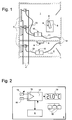
- Fig. 1 means a first living space, while 2 denotes a second living space.
- Each of the living rooms 1, 2 has at least one heat exchanger 3 for delivering thermal energy to the room.
- heat exchangers 3 are designed as radiators, the size and number of which depends on the conditions of the heating system and the rooms.
- Each heat exchanger 3 is connected to a heat generator (not shown) via transport lines 4, for example a flow line and a return line.
- transport lines 4 for example a flow line and a return line.
- a controller for regulating the temperature of a heat transfer medium which is heated by the heat generator and circulates in these transport lines 4.
- An actuator 5 is attached to each of the heat exchangers 3, with the aid of which the flow of the heat transfer medium through the heat exchanger 3 can be influenced.
- These actuators 5 consist of a valve and an actuator influencing this valve.
- the actuator can be, for example, a simple, manually operated rotary knob in heating systems according to the prior art.
- Thermal drives that have a self-regulating effect on temperature are also common. In the prior art, there are valves that are designed so that their drives can be replaced very easily.
- the drives are electrically controllable.
- the drives can have an electric motor or an electrothermal effect.
- a motor is included that can be controlled in the opening or closing direction.
- there can be a thermal drive which automatically controls the flow through the heat exchanger on the one hand, but can also be controlled from the outside on the other hand.
- an electrically controllable heating element can be included.
- a remote control device 6 and a control box 7 are assigned to each room 1, 2.
- the remote control device 6 is battery-powered, for example, so that it can be placed anywhere within the rooms 1, 2 without regard to cabling.
- 1 shows that the remote control device 6 is in room 1 on a table 8, while in room 2 it is attached to the wall of room 2.
- the remote control device 6 has a transmitting device 9, by means of which control signals can be distributed wirelessly.
- the control box 7 assigned to each room 1, 2 has a receiving device 10 with which the control signals sent wirelessly by the remote control device 6 can be received.
- Each control box 7 can be connected to a socket 12 of the usual mains power supply by means of a power cord 11.
- the control box 7 also has connections for wire connections 13, via which the control box 7 acts electrically on the drives of the actuators 5 connected to the control box 7. These wire connections 13 can be freely laid in rooms 1, 2.
- FIG. 2 The structure of a remote control device 6 is shown schematically in FIG. 2.
- This contains a room temperature sensor 14 and a setpoint adjuster 15.
- the user can set the desired setpoint of the room temperature on the setpoint adjuster 15.
- the actual value of the room temperature determined by the room temperature sensor 14 is compared by a comparator 16 with the target value.
- the comparator 16 is, for example, part of a digital system 17 which, in a known manner, consists of a processor and a memory.
- the setpoint adjuster 15 can also be a component of this digital system 17, in which case the setpoint is then set with the aid of control buttons 18, which are present anyway and interact with the digital system 17.
- a display device 19, for example an LCD display, is also connected to the digital system 17.
- the remote control device 6 also contains the transmission device 9 already mentioned in the description of FIG. 1.
- the remote control device 6 contains a battery, not shown, which supplies the electrically functioning parts of the remote control device 6 with the necessary voltage and current. If the use of a battery should be avoided, the use of an external power supply is alternatively conceivable. For example, a power supply unit integrated into a plug could be used, for which the known prior art offers models. Another alternative would be to use solar cells together with a generously sized capacitor.
- the remote control device 6 can contain a receiver for the signals of one of the known long-wave time transmitters, with which an internal clock is controlled which is associated with the expiry of Time programs are needed.
- the remote control device 6 can contain a receiver for the signals of one of the known long-wave time transmitters, with which an internal clock is controlled which is associated with the expiry of Time programs are needed.
- different setpoints of the room temperature can be assigned to different time periods, as is generally known.
- the digital system 17 From the difference between the actual value and the target value of the room temperature, the digital system 17 generates an actuating signal for the drives of the actuators 5. This actuating signal is fed to the transmitting device 9 and transmitted wirelessly by the latter.
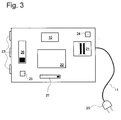
- This signal can be received by the control box 7, the details of which are shown in FIG. 3.
- the control box 7 can be connected to the existing standard mains power supply by means of a mains connection cable 11, which is why the mains connection cable 11 is provided with a mains plug 20 at its free end.
- a transformer 21 which can be switched from 230 V to 115 V, for example with regard to the prevailing mains voltages.
- This transformer 21 generates a low voltage of, for example, 24 V, which is also the operating voltage for the drives of the actuators 5 (FIG. 1).
- the use of low voltage for this purpose has the advantage that no high demands have to be made on the plug connectors and on the wire connections 13 (FIG. 1).
- the control box 7 has the receiving device 10 already mentioned, which is also operated by the low voltage.
- the signal of the receiving device 10 reaches a switching device 22.
- This switching device 22 has outputs which lead to plug sockets 23 to which the wire connections 13 provided with suitable plugs can be connected.
- the control box 7 advantageously also has two control lamps, namely a first control lamp 24 with which the presence of the mains voltage is indicated, and a second control lamp 25 with which the establishment of the wireless connection from the remote control device 6 to the control box 7 can be indicated.
- FIG. 3 also shows a first switch 26, for example a slide switch, which is used to switch the control box 7 on and off.
- a selector switch 27 may also be present. This selector switch 27 is used, for example, to select one of several possible transmission channels and, if this option is provided, is also present in the remote control device 6 (FIG. 2), but is not shown there. With the possibility of being able to set different transmission channels, the problem of influencing devices of the type described which are arranged in adjacent rooms 1, 2 can be solved.
- the switch 26 can alternatively also be designed to switch the remote control effect on and off.
- the control box 7 acts as described above, that is to say it is controlled by the remote control device 6.
- the influence by the remote control device 6 is switched off, so that the control box 7 can be operated autonomously.
- the control box 7 controls the connected actuators 5 continuously in the OPEN position and in the third position in the CLOSED position. This enables manual control by the user.
- room temperature control can be implemented with the device described above in FIGS. 1 to 3.
- the setup described works as follows.
- a control signal for the actuator 5 is generated in the digital system 17 in a known manner.
- This control signal is applied to the transmitting device 9, which then emits a corresponding signal.
- This signal can be received by the control box 7.
- the signal is processed so that the actual control signal for the actuator 5 is recovered.
- a corresponding control command now reaches the control element 5 via the wire connection 13.
- the control element 5 is actuated in accordance with the respective control signal either in the opening direction or in the closing direction.
- Actuation in the opening direction takes place when the actual value of the room temperature is lower than the target value of the room temperature, and accordingly in the closing direction when the actual value of the room temperature is greater than the target value of the room temperature.
- Control algorithms known to those skilled in the art are used here.
- a first package contains a remote control device 6 and a control box 7 with a ready-made power cord 11 and an electric drive for an actuator 5 with wire connection 13.
- a second package contains an electric drive for an actuator 5 with wire connection 13.
- the device according to the invention is shown schematically.
- the person skilled in the art has many different possibilities for the design of the apparatus. This also applies, for example, to the medium for wireless transmission between the remote control device 6 and the control box 7.
- the use of ultrasound or infrared light can be considered as well as the use of radio waves.
- the design can also be different in terms of whether actuators 5 with continuous adjustment options or simple OPEN / CLOSE valves are used. It is advantageous if the remote control device 6 is programmable in such a way that the control buttons 18 can be used to set whether actuators 5 with continuous adjustment or simple OPEN / CLOSE valves are used in connection with the remote control device 6. This programming generates different control signals.
- the digital system 17 contains appropriate program code for both types of control, one of which is activated in each case. It is thereby achieved that no different variants of remote control device 6 and control box 7 are required in order to be able to control throttle bodies 5 of different types.
- the remote control device 6 can be battery-operated, the person skilled in the art will choose an embodiment that is as energy-saving as possible.
- the design of the wireless transmission can also be used with appropriate techniques.
- the latter possibility should be taken into consideration simply because the control box 7 can be placed anywhere in the room 1, 2, that is to say can also be removed. It can therefore also be advantageous to display the switchover and / or decommissioning of the control box 7 on the display device 19 of the remote control device 6 (FIG. 2).
Landscapes
- Engineering & Computer Science (AREA)
- Physics & Mathematics (AREA)
- Thermal Sciences (AREA)
- Chemical & Material Sciences (AREA)
- Combustion & Propulsion (AREA)
- Mechanical Engineering (AREA)
- General Engineering & Computer Science (AREA)
- General Physics & Mathematics (AREA)
- Automation & Control Theory (AREA)
- Selective Calling Equipment (AREA)
- Steam Or Hot-Water Central Heating Systems (AREA)
Applications Claiming Priority (2)
| Application Number | Priority Date | Filing Date | Title |
|---|---|---|---|
| CH109796 | 1996-05-01 | ||
| CH1097/96 | 1996-05-01 |
Publications (2)
| Publication Number | Publication Date |
|---|---|
| EP0805311A2 true EP0805311A2 (fr) | 1997-11-05 |
| EP0805311A3 EP0805311A3 (fr) | 1998-11-04 |
Family
ID=4202413
Family Applications (1)
| Application Number | Title | Priority Date | Filing Date |
|---|---|---|---|
| EP96120034A Withdrawn EP0805311A3 (fr) | 1996-05-01 | 1996-12-13 | Dispositif de réglage pour installation de chauffage |
Country Status (2)
| Country | Link |
|---|---|
| EP (1) | EP0805311A3 (fr) |
| CZ (1) | CZ130297A3 (fr) |
Cited By (9)
| Publication number | Priority date | Publication date | Assignee | Title |
|---|---|---|---|---|
| FR2788842A1 (fr) * | 1999-01-27 | 2000-07-28 | Micrel | Dispositif de regulation de chauffage a circulation d'eau |
| EP1225396A3 (fr) * | 2000-11-15 | 2003-03-19 | Fly S.R.L. | Appareil pour actionnement automatique des valves pour arrêter l'alimentation en fluide d'un élément de chauffage |
| EP1116921A3 (fr) * | 2000-01-14 | 2003-11-12 | ELMOS Semiconductor AG | Système de conditionnement d'air d'un local pour bâtiments |
| EP1460347A1 (fr) * | 2003-03-20 | 2004-09-22 | Buderus Heiztechnik GmbH | Procédé de régulation pour une installation de chauffage |
| DE102006037996A1 (de) * | 2006-08-14 | 2008-02-21 | Andreas Pfister | Sensoreinheit, Heizungssteuerung und Verfahren zur Heizungssteuerung |
| WO2009072758A2 (fr) | 2007-12-04 | 2009-06-11 | Kyungdong Network Co., Ltd. | Procédé de contrôle de système de chauffage |
| DE102008007526A1 (de) * | 2008-02-05 | 2009-08-06 | Robert Bosch Gmbh | Mobile Fernbedienungseinheit |
| DE102011015659A1 (de) | 2011-03-31 | 2012-10-04 | IPcontrols AG | System und Verfahren zur Ansteuerung eines Thermostatventils |
| CN103471162A (zh) * | 2013-09-26 | 2013-12-25 | 王波兰 | 电暖器设备 |
Citations (2)
| Publication number | Priority date | Publication date | Assignee | Title |
|---|---|---|---|---|
| DE3315164A1 (de) | 1983-04-27 | 1984-10-31 | HERWI-Solar GmbH Solar- und Wärmepumpentechnik, 8761 Röllbach | Raumtemperaturregelungs- oder -steuerungseinrichtung fuer eine heizungsanlage |
| DE4221094A1 (de) | 1992-06-26 | 1994-01-05 | Buderus Heiztechnik Gmbh | Verfahren zur Raumtemperaturregelung |
Family Cites Families (3)
| Publication number | Priority date | Publication date | Assignee | Title |
|---|---|---|---|---|
| DE3308099C2 (de) * | 1983-03-08 | 1986-03-13 | Helmut Hund KG, 6330 Wetzlar | Verfahren zur drahtlosen Übertragung eines Parameters zur Regelung der Temperatur eines Raumes sowie eine Vorrichtung zur Durchführung dieses Verfahrens |
| AT396852B (de) * | 1991-07-31 | 1993-12-27 | Vaillant Gmbh | Einrichtung zur regelung der raumtemperatur |
| DE59407281D1 (de) * | 1994-03-01 | 1998-12-17 | Landis & Gyr Tech Innovat | Regeleinrichtung für mehrere Einzelgeräte |
-
1996
- 1996-12-13 EP EP96120034A patent/EP0805311A3/fr not_active Withdrawn
-
1997
- 1997-04-29 CZ CZ971302A patent/CZ130297A3/cs unknown
Patent Citations (2)
| Publication number | Priority date | Publication date | Assignee | Title |
|---|---|---|---|---|
| DE3315164A1 (de) | 1983-04-27 | 1984-10-31 | HERWI-Solar GmbH Solar- und Wärmepumpentechnik, 8761 Röllbach | Raumtemperaturregelungs- oder -steuerungseinrichtung fuer eine heizungsanlage |
| DE4221094A1 (de) | 1992-06-26 | 1994-01-05 | Buderus Heiztechnik Gmbh | Verfahren zur Raumtemperaturregelung |
Cited By (13)
| Publication number | Priority date | Publication date | Assignee | Title |
|---|---|---|---|---|
| FR2788842A1 (fr) * | 1999-01-27 | 2000-07-28 | Micrel | Dispositif de regulation de chauffage a circulation d'eau |
| EP1024330A1 (fr) * | 1999-01-27 | 2000-08-02 | Micrel Société Anonyme | Dispositif de régulation de chauffage à circulation d'eau |
| EP1116921A3 (fr) * | 2000-01-14 | 2003-11-12 | ELMOS Semiconductor AG | Système de conditionnement d'air d'un local pour bâtiments |
| EP1225396A3 (fr) * | 2000-11-15 | 2003-03-19 | Fly S.R.L. | Appareil pour actionnement automatique des valves pour arrêter l'alimentation en fluide d'un élément de chauffage |
| EP1460347A1 (fr) * | 2003-03-20 | 2004-09-22 | Buderus Heiztechnik GmbH | Procédé de régulation pour une installation de chauffage |
| DE102006037996A1 (de) * | 2006-08-14 | 2008-02-21 | Andreas Pfister | Sensoreinheit, Heizungssteuerung und Verfahren zur Heizungssteuerung |
| WO2009072758A2 (fr) | 2007-12-04 | 2009-06-11 | Kyungdong Network Co., Ltd. | Procédé de contrôle de système de chauffage |
| EP2225497A4 (fr) * | 2007-12-04 | 2015-11-11 | Kyungdong One Corp | Procédé de contrôle de système de chauffage |
| DE102008007526A1 (de) * | 2008-02-05 | 2009-08-06 | Robert Bosch Gmbh | Mobile Fernbedienungseinheit |
| EP2088799A3 (fr) * | 2008-02-05 | 2014-04-09 | Robert Bosch GmbH | Unité de télécommande mobile |
| DE102011015659A1 (de) | 2011-03-31 | 2012-10-04 | IPcontrols AG | System und Verfahren zur Ansteuerung eines Thermostatventils |
| DE202011110079U1 (de) | 2011-03-31 | 2012-12-04 | 3U Holding AG | System zur Ansteuerung eines Thermostatventils |
| CN103471162A (zh) * | 2013-09-26 | 2013-12-25 | 王波兰 | 电暖器设备 |
Also Published As
| Publication number | Publication date |
|---|---|
| EP0805311A3 (fr) | 1998-11-04 |
| CZ130297A3 (en) | 1997-11-12 |
Similar Documents
| Publication | Publication Date | Title |
|---|---|---|
| DE3490205C2 (fr) | ||
| DE69416353T2 (de) | Temperaturregelsystem mit einer Steuerungszentrale für Thermostaten | |
| DE102017123560B4 (de) | Selbstregulierende Einstellvorrichtung für ein Durchflussregelventil | |
| EP0729086B1 (fr) | Procédé et dispositif pour réguler un système de chauffage par température basse | |
| EP0208256B1 (fr) | Dispositif de régulation de la température d'un local | |
| EP2702331A2 (fr) | Procédé et système pour l'équilibrage hydraulique automatique de radiateurs | |
| EP0805311A2 (fr) | Dispositif de réglage pour installation de chauffage | |
| EP1640669B1 (fr) | Appareil de chauffage de locaux | |
| AT399218B (de) | Verfahren zur steuerung der aufheizung von räumen eines gebäudes | |
| DE60023079T2 (de) | Steuervorrichtung für Kreislaufanlage für Warmeträgerflüssigkeit | |
| EP0040689A1 (fr) | Dispositif de réglage et de préréglage d'opérations d'enclenchement et de déclenchement et de gammes de condition | |
| DE2636195A1 (de) | Anlage zum beheizen eines gebaeudes | |
| DE102011015659A1 (de) | System und Verfahren zur Ansteuerung eines Thermostatventils | |
| DE2908147C2 (de) | Raumgerät, das über Leitungen mit einem witterungsgeführten Regler zum Regeln der Vorlauftemperatur verbunden ist | |
| DE4309121A1 (de) | Regelvorrichtung für ein Heizkörperventil | |
| DE10312668B3 (de) | Raumtemperaturregelsystem | |
| DE2253511A1 (de) | Anordnung zum selbsttaetigen regeln der temperatur eines raumes | |
| DE3539327C2 (de) | Schaltung zur Steuerung einer Zentralheizungsanlage | |
| DE3045753A1 (de) | Einrichtung zum steuern der ueber raumthermostaten geregelten heizkoerperventile einer zentralheizungsanlage | |
| CH672852A5 (fr) | ||
| DE19716863A1 (de) | Fußbodenheizung mit einer Temperaturregeleinrichtung | |
| DE102023103643A1 (de) | Vorrichtung für ein Heizsystem sowie Heizsystem und Verfahren zu dessen Betrieb | |
| DE2756860C3 (de) | Steuersystem fur die Heizungsanlage eines Mehrfamilienhauses | |
| DE4213072C2 (de) | Verfahren zum Betreiben eines elektrischen Speicherheizgeräts | |
| DE102010049193A1 (de) | Vorrichtung und Verfahren für einen Ventilaufsatz mit bevorzugter Verwendung am Heizkörper |
Legal Events
| Date | Code | Title | Description |
|---|---|---|---|
| PUAI | Public reference made under article 153(3) epc to a published international application that has entered the european phase |
Free format text: ORIGINAL CODE: 0009012 |
|
| AK | Designated contracting states |
Kind code of ref document: A2 Designated state(s): AT CH DE FR GB IT LI |
|
| PUAL | Search report despatched |
Free format text: ORIGINAL CODE: 0009013 |
|
| AK | Designated contracting states |
Kind code of ref document: A3 Designated state(s): AT CH DE FR GB IT LI |
|
| STAA | Information on the status of an ep patent application or granted ep patent |
Free format text: STATUS: THE APPLICATION IS DEEMED TO BE WITHDRAWN |
|
| 18D | Application deemed to be withdrawn |
Effective date: 19990701 |