EP0040995A2 - Optische Aufnahme-Wiedergabe-Vorrichtung für einen Informationsträger - Google Patents
Optische Aufnahme-Wiedergabe-Vorrichtung für einen Informationsträger Download PDFInfo
- Publication number
- EP0040995A2 EP0040995A2 EP81400689A EP81400689A EP0040995A2 EP 0040995 A2 EP0040995 A2 EP 0040995A2 EP 81400689 A EP81400689 A EP 81400689A EP 81400689 A EP81400689 A EP 81400689A EP 0040995 A2 EP0040995 A2 EP 0040995A2
- Authority
- EP
- European Patent Office
- Prior art keywords
- optical
- axis
- recording
- polarization
- reading
- Prior art date
- Legal status (The legal status is an assumption and is not a legal conclusion. Google has not performed a legal analysis and makes no representation as to the accuracy of the status listed.)
- Granted
Links
Images

Classifications
-
- G—PHYSICS
- G11—INFORMATION STORAGE
- G11B—INFORMATION STORAGE BASED ON RELATIVE MOVEMENT BETWEEN RECORD CARRIER AND TRANSDUCER
- G11B7/00—Recording or reproducing by optical means, e.g. recording using a thermal beam of optical radiation by modifying optical properties or the physical structure, reproducing using an optical beam at lower power by sensing optical properties; Record carriers therefor
- G11B7/12—Heads, e.g. forming of the optical beam spot or modulation of the optical beam
Definitions
- the invention relates to an optical device for recording and reading information media.
- the invention relates more particularly to recorder-reader systems in which the information medium is a disc.
- the information medium is a disc.
- These systems can be used as mass storage for digital data processing sets.
- These systems must allow random access to a predetermined part of the recorded data, for example a block of binary words of fixed or variable length.
- the speed of calculation of the information processing units requires numerous exchanges between the peripheral memories and these calculation units. It is therefore necessary that access to a predetermined track of a mobile information medium takes place in the shortest possible time, both for reading prerecorded information and for recording such information, whatever the position. of this track on the disc.
- the average access time must be less than 100 milliseconds.
- the current track access devices are essentially intended for discs on which the recorded information contains a video signal in digital form.
- the access time to information is in the order of a few seconds, which is sufficient for this application.
- the correct radial positioning of an optical recording and / or reading head is achieved by mechanical means ensuring either the movement of this head, or most often the movement of the disc.
- the radial tracking of the circular or helical track on which the information must be (or is) recorded is carried out using '' a galvanometric mirror movable around an axis parallel to the plane of the disc and which reflects a beam produced by at least one radiant energy source comprising a laser.
- the head also includes a device ensuring the vertical slaving of the objective used for recording-reading. In reality two sources are most often provided: one for reading and one for recording.
- the mobile equipment has a mass too large to be compatible with the average access times desired in IT.
- the disc being integral with a rotating mechanism, including in particular the drive motor, a mass of the order of 1 Kg must be put in place. movement.
- the energy source 1 lasers remaining fixed and comprising for example afocal type optical means ensuring the optical coupling between the light energy source and record-read head.
- Such a device comprises a movable assembly comprising a galvanometric mirror and a focusing objective, movable relative to the information medium, and two fixed radiant energy sources each comprising a laser transmitter.
- the magnifying optical means of the afocal type are inserted between the mobile assembly and the radiant energy sources; the magnification being sufficient for the beam emerging from the optical means to completely cover the entrance pupil of the objective.
- the device which has just been described is perfectly suited to the use of gas lasers. It is not the same if one uses the semiconductor laser sources which have been introduced more recently. These lasers requiring collimating optics are equivalent to a source of large useful emission diameter. It is no longer possible to use an afocal.
- the invention proposes a recording-reading device which remains compact, allowing perfect separation of the reflected recording and reading beams, and retaining a satisfactory energy efficiency.
- the object of the invention is also the use of such a device in an optical memory.
- the invention relates to an optical device for recording and reading information media, in particular in the form of discs, it is useful to recall its constituent elements.
- Such discs can be used either to record information at a determined point on a smooth track entered in the to read information entered at any point on this track.
- the disc with a diameter of about 30 cm is driven in a rotational movement which is communicated to it by a drive motor secured to the chassis of the optical recording / reading device.
- the invention relates more particularly to devices of the type comprising a fixed part constituted by the light energy sources and a mobile part constituted by the recording-reading head.
- the latter comprises a microscope type objective, integral with an electromagnetic coil moving in the magnetic field of a permanent magnet ensuring the vertical control and a galvanometric mirror ensuring the radial control.
- FIG. 1 illustrates an exemplary embodiment of an optical recording-reading device of the type described above and using gas laser sources, to produce radiant energy, for example HeNe gas lasers. These lasers emit a polarized parallel beam. As is known, the section of this beam is very small and must therefore be enlarged.
- the device comprises two sources: a source emitting a reading beam f and a source emitting a recording beam f. These sources are not shown in Figure 1.
- the parallel and polarized beam f I is enlarged using an afocal 1 whose magnification is such that the emerging beam, also parallel, covers the entrance pupil of an objective O b of microscope type.
- a galvanometric mirror M is inserted between afocal 1 and objective O b so as to deflect the rays propagating parallel to the optical axis at, along the axis ⁇ z .
- the axes ⁇ x and ⁇ z are respectively parallel to the axes X and Y of the reference trihedron XYZ.
- the objective O b focuses the reading beam at point 3 on the information support disk 5. This disk is driven in a rotation movement symbolized by the arrow 6.
- the objective O b and the mirror M are integral d 'a moving assembly 2 constituting the recording-reading head.
- the advance of this mobile assembly can be obtained by any known means and, for example without limitation, either using a ribbon driven by pulleys (as is the case with curve plotters), or thanks to a nut and a screw causing balls (as on some recorder-players and so-called "Floppy-discs” systems), or again by a linear motor.
- the moving part can move along the axis ⁇ z , driven by servo means so that the reading beam is focused exactly on the tracks 7 carrying the information to be read.
- the mirror M is movable around the axis ⁇ y to ensure a radial control.
- a well-known method for recording information consists in forming microcuvettes or more generally microreliefs on the surface of the disc 5 of variable length along the direction of the tracks 7. These tracks are in the form of a single spiral or of concentric circles .
- the variable length of the microcuvettes or microreliefs is representative of a duration modulation of the information to be recorded.
- the reading is carried out by reflection of the reading beam focused at 3 on a reflecting surface, for example a metallic deposit made on the face of the disc carrying the microcuvettes.
- the reading beam is spatially modulated by the microreliefs, this modulation representing the information recorded on the read side of the disc.
- the reflected beam follows the same path as on the outward journey and is detected by optoelectronic members (not shown in FIG. 1).
- the signals thus detected are used for several purposes: in addition to their use for the reconstitution of the information read from the disk 5, these signals are also used to provide the servo controls previously signaled.
- Such processes have been described, by way of nonlimiting example, in the following two patent applications: French patent application No. 75.29.705, filed on September 29, 1975 and published under No. 2,325,953; and French patent application No. 74.01.283, filed on January 15, 1974 and published under No. 2,271,590.
- the same afocal is used for the recording beam, which having been previously modulated in a conventional manner.
- the recording beam f is very slightly inclined with respect to the reading beam f by an angle u 'at the output of the afocal 1.
- the transverse magnification is given by relationship . This magnification is chosen much more larger than 1, it follows that the angle ratio is less than 1, u being the angle between the axes A and ⁇ 'of the reading beams f l and writing f e at the input of the afocal.
- the shift of the recording spot on the entrance pupil of the lens is therefore very limited. One can also neglect this displacement during a radial displacement of the head.
- the recording beam is focused at the focal point of the objective while ensuring good discrimination, at the output of the afocal , beams of recording f e and of reading f I since, conversely, the ratio is much greater than 1.
- this recording-reading device dissociating the radiant energy sources from the recording-reading head proper, makes it possible to reduce the mass of the mobile assembly to around 200 grams, including 100 grams for the device. slaving along the axis ⁇ z and 30 grams for the galvanometric mirror M and its drive device, the objective having a negligible weight. This reduced mass reduces the inertia of the recording-reading device and allows a sufficiently short access time to information for computer applications.
- the device which has just been described is perfectly suited to the use of gas laser sources. It is not the same if one uses the sources with semiconductor lasers which were introduced more recently. These lasers are in the form of an emissive disc and are characterized by a very divergent emission, in a cone of about 30 °. They require the implementation of a collimator optic. The assembly is equivalent to a large diameter emission source: typically 7 mm.
- the two beams, of recording f e and of reading f l respectively must be focused on the disc 5 in very close locations, so that the recording 4 and reading 3 spots are practically merged to remain in the record-read objective field O b .
- the focal length of this lens is usually very small. It follows that the angle u 'made between them by the two incident beams of reading and writing is very small.
- the section of the emitted beams is therefore sufficient to cover the entrance pupil of the projection objective without intermediate optical means such as afocal 1 and given the short focal distance of the objective recording-reading O b as well as the short distance separating the reading 3 and recording 4 spots, it is then necessary to place the energy detection members of the reflected beams at a very great distance from the objective O b , which leads to bulky devices.
- FIG. 2 If the distance between the reading 3 and recording 4 spots is 1, the focal distance of the objective O b is f, the angle u ′ which make the beams d between them 'recording f e and reading f 1 is given by the relation:
- optical discrimination means making it possible to reduce this bulk.
- these optical means must not be the cause of significant energy losses. This would be the case, for example, of semi-transparent mirrors.
- the invention proposes to meet these needs.
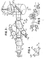
- FIG. 3 illustrates a first alternative embodiment of an optical recording-reading device according to the invention.
- This device includes three subsets.
- a first subset constitutes a composite source of radiant energy. This source is intended to produce a composite beam, comprising two components each in the form of a polarized parallel beam, respectively for reading and recording. These two beams are slightly inclined with respect to one another as it has been recalled previously in connection with FIGS. 1 and 2.
- the two laser sources thus formed emit in directions substantially parallel to the axes ⁇ x and ⁇ l , parallel to the axes X and Y of a reference trihedron XYZ.
- This element illustrated in more detail in FIG. 8 can be a parallelepiped of refractive material. In a preferred variant of the invention, it is a cube 80 consisting of two bonded prisms 81 and 82. The separation surface 83 formed by the hypotenuse of the two prisms is treated so as to be polarization separator. This element has a preferential optical axis 84.
- the incident rays R i having a direction of polarization parallel to this axis are transmitted in full without modification along the direction of emergence R, parallel to the direction of incidence, and the incident rays R ' i having a direction of polarization orthogonal to the previous direction are completely reflected along the direction of emergence R o orthogonal to the direction of incidence.
- the faces of the cube have also undergone a surface treatment to avoid stray reflections. This treatment is known to those skilled in the art.
- optical elements can be used in the context of the invention, this is particularly the case for certain birefringent polarizers such as the GLAN prism.
- a polarizer transmitting the incident rays of a first direction of polarization without modification and totally reflecting the rays of direction of polarization orthogonal to the previous direction.
- the two components whose polarization directions are orthogonal then pass through an optical element 11 constituted by a polarizer whose optical axis makes a determined angle with the polarization directions of the reading and recording components.
- This polarizing element 11 will be explained later in relation to the diagram in FIG. 4.
- the two components emerge from the polarizing element 11 with a common direction of polarization, parallel to that of the polarizer.
- the resulting composite beam then crosses a second cube 20, identical to the cube 10 previously described. If this cube is oriented properly, the two components of the same direction of polarization, respectively of reading and recording, forming the composite beam, will be transmitted entirely by the cube 20.
- This cube 20 in combination with detection members comprising the optics convergent symbolized by the lens L 3 and opto-electronic detection means D as well as a quarter-wave plate 21 placed at the outlet of the cube, constitutes the second subset of the optical recording-reading device of the invention .
- the purpose of the quarter wave plate 21 is to transform the linear polarizations of the two components of the composite beam into a polarization circular, for example in the levogyre direction.
- the optical axis of the blade must make an angle of ⁇ / 4 radians with the direction of polarization of the composite beam. 1
- the composite beam emerging from the quarter-wave plate 21 enters the third sub-assembly of the recording-reading device of the invention constituted by a recording-reading head 2 in all points identical to that of FIG. 1 As for the device described in relation to this figure, only the recording-reading head is movable relative to the tracks carrying the information 7. Les. two components of the composite beam are reflected by a galvanometric mirror M, towards the objective O b to be focused on the face of the disc carrying the information tracks 7, in two spots of reading 3 and recording 4 respectively.
- the two components of the composite beam follow the opposite optical path and are always circularly polarized, but in the dextrorotatory direction.
- the composite beam transmitted from the polarizing cube 20 is again linearly polarized.
- the new direction of polarization, common to the two components of the composite beam after reflection on the disc is orthogonal to that of the original beam. It follows that when crossing the cube 20 the two components of the composite beam will be reflected by the face common to the two prisms of this cube, along the axis ⁇ 2 , orthogonal to the axis O X.
- a focusing optic symbolized by the lens L 3 focuses the two components of the emerging composite beam into two spatially distinct spots, included in a plane containing the optoelectronic detection means D.
- This element can be a simple polarizing filter.
- the two components respectively of recording and of reading have linear polarization directions orthogonal between them. It is therefore necessary to obtain a common polarization direction for these two components are transmitted entirely by the polarizing cube 20 without total parasitic reflection (which would imply the extinction of one of the two components) or partial of at least one of these two components (which can be annoying). It is a first goal of this polarizer. It also makes it possible to measure, the relative intensities of the two components of the emerging composite beam. Indeed, it is necessary to have the maximum energy during recording since the focused beam is used to create within the material constituting the optical disc disturbances by thermal effect. It is sufficient, on the other hand, that at least a fraction of the intensity of the reading beam is transmitted entirely by the polarizing cube 20. The use of a semitransparent mirror transmitting or selectively reflecting two equally polarized components would not have allowed this. dosage.
- the diagram in Figure 4 illustrates this aspect.
- the components of the composite beam emerging from the cube 10 have polarization directions P z and Py, respectively parallel to the reference axes Z and Y.
- the intensities of these components are represented by the vectors Il and 1 2 .
- the polarizer 11 has a direction of polarization P, making an angle a with the direction of polarization Py (that is to say with the axis Y), the resulting intensities of the two reading and recording components are respectively I ' 1 and 1 ' 2 .
- the angle a is chosen to be less than ⁇ / 2 radians so as to favor the component of the composite beam used for recording.
- the rotation of the cube 20 (and of the quarter-wave plate 21 which is linked to it) around the axis ⁇ X brings no disturbance to the emerging composite beam because the latter has a symmetry of revolution since its two components are circularly polarized at the output of the quarter-wave plate 21.
- the angle of inclination of the axes of symmetry of the two components is very small, as has been recalled, these axes being practically coincident with the axis ⁇ X. Conveniently this slight tilt can be obtained by offsetting one of the laser sources, for example by offsetting the laser source La 2 relative to the axis ⁇ l .
- the optoelectronic detection member D can comprise four photodiodes D 1 to D 4 arranged in a plane perpendicular to the axis ⁇ 2 , in the configuration illustrated in FIG. 5.
- the lens L 3 focuses on the plane of the photo-diodes, the two components of the composite beam reflected in two separate spots of reading 3 'and recording 4' respectively.
- the output signals of photodiodes D 1 and D 2 are transmitted to the inputs of two differential amplifiers A 1 and A 2 , the first effecting the sum of the output signals of photodiodes D 1 and D 3 , and the second difference of these same signals.
- the signals present on the output S 1 of the amplifier A 1 can be used to elaborate signals representing the information read on the disc and the signals present on the output S 2 of the amplifier A 2 to elaborate servo signals vertical of the record-read head 2 (figure 3).
- the outputs of photodiodes D 3 and D 4 are connected to a third differential amplifier A 3 carrying out the sum of the signals present on the outputs of these photodiodes.
- the signals present on the output S 3 of the differential amplifier A 3 can be used to generate signals representing the signals being recorded and thus control this recording.
- Radial tracking of the track on the disc can be obtained by using the recording beam, by connecting the outputs of photodiodes D 3 and D 4 to a fourth differential amplifier A 4 , effecting the difference of the output signals of photodiodes D 3 and D 4 .
- the signals present on the output S 4 of this differential amplifier A 4 can be used to generate error signals.
- the optical recording-reading device of the invention therefore allows good discrimination of the respective reading and recording components of the composite beam, while remaining compact and maintaining good energy efficiency, in particular for the component used during recording.
- the device according to the architecture described in relation to FIG. 3 however requires that the two cubes 10 and 20 be movable relative to one another, so as to make the axis of polarization of the polarizer 11 coincide with the optical axis of the cube 20.
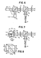
- FIG. 6 illustrates a recording-reading device according to the invention in which the two cubes 10 and 20 are fixed relative to one another.
- the polarizer 11 of FIG. 3 has been replaced by a half-wave plate 11 ', which can be oriented around the axis ⁇ X.
- a half-wave plate whose optical axis makes an angle with the axis of polarization of a polarized beam rotates this axis by an angle 2 a.
- the components of the composite beam emerging from the cube 10 will therefore see their directions of polarization rotate respectively by an angle 2a and by an angle , the angle being expressed in radians.
- the prism 20 plays the role of an analyzer for these components and transmits along the ⁇ X axis the two reading and recording components, the intensity of which is equal to the projection of the vectors representing the intensities of these same components.
- the two components thus transmitted by the cube 20, have the same direction of polarization, that of the optical axis of the cube.
- the other elements are identical to the elements described in relation to FIG. 3 and will not be described again.
- the prism 10 and the laser sources La l -L 1 and La2 L2 can be substituted for a stigmatic optical device for emitting coherent coherent radiation.
- a stigmatic optical device for emitting coherent coherent radiation.
- FIG. 7 This variant of the present invention is illustrated in FIG. 7.
- the element 100 comprises a parallelepiped 101. Unless otherwise stated, in the following description, it is a cube made up of two. bonded prisms.
- the separation surface 102 formed by the hypothesis nuse of the two prisms is treated so as to be polarization separator: it transmits all of the radiation having a given polarization and it reflects all of the radiation having a direction of polarization orthogonal to the previous one.
- a plano-convex lens 10 ", formed of the same material as the cube, is bonded to one of the faces 104 of the cube.
- the first condition gives the relationship between the thickness e of the set and the radius R: .
- this relation is verified, if one places in A a source of radiation polarized in the direction corresponding to a transmission by the face 102, emitting a divergent beam of half-angle at the summit ⁇ o , in air, this angle becomes ⁇ in the cube and the beam emerging from the lens, coming from the virtual point A 1 , has a half-angle at the vertex ⁇ 1 with and .
- the element 101 being cubic, the point B conjugate of A with respect to the face 102 is located on another face of the cube and is also a stigmatic point.
- a beam coming from B with a direction of polarization orthogonal to that of the beam coming from A is reflected by the face 102 and is superimposed on the beam coming from A.
- the optical unit 100-103 can also be produced in such a way that the face 104 is not materialized.
- the element 100 described is intended to be used in association with semiconductor lasers La 1 and La 2 having their phase center at A and B.
- An objective symbolized by the lens L ′ of optical axis coincident with the axis ⁇ X is placed behind the lens 103, so that its focus is at the point At 1 .
- This objective is designed so as not to present spherical aberrations for the maximum beam apertures provided by the lasers placed at A and B, the entire optical system having to remain stigmatic. It may for example be a doublet and the composite parallel beams of the devices previously described in relation to FIGS. 3 and 6 are therefore obtained.
- the elements 10 or 20 can be constituted by any optical element transmitting integrally a beam polarized in a second direction orthogonal to the first direction of polarization, the direction of reflection not necessarily being orthogonal to the direction of transmission.
- the angle made by these two directions must however be large enough to facilitate the practical realization of the device of the invention.
Landscapes
- Physics & Mathematics (AREA)
- Optics & Photonics (AREA)
- Optical Head (AREA)
- Optical Recording Or Reproduction (AREA)
Applications Claiming Priority (2)
| Application Number | Priority Date | Filing Date | Title |
|---|---|---|---|
| FR8011801A FR2483664B1 (fr) | 1980-05-28 | 1980-05-28 | Dispositif optique d'enregistrement-lecture sur un support d'informations et systeme de memoire optique comprenant un tel dispositif |
| FR8011801 | 1980-05-28 |
Publications (3)
| Publication Number | Publication Date |
|---|---|
| EP0040995A2 true EP0040995A2 (de) | 1981-12-02 |
| EP0040995A3 EP0040995A3 (en) | 1981-12-09 |
| EP0040995B1 EP0040995B1 (de) | 1984-04-04 |
Family
ID=9242409
Family Applications (1)
| Application Number | Title | Priority Date | Filing Date |
|---|---|---|---|
| EP81400689A Expired EP0040995B1 (de) | 1980-05-28 | 1981-04-30 | Optische Aufnahme-Wiedergabe-Vorrichtung für einen Informationsträger |
Country Status (6)
| Country | Link |
|---|---|
| US (1) | US4399529A (de) |
| EP (1) | EP0040995B1 (de) |
| JP (1) | JPS5720932A (de) |
| CA (1) | CA1159149A (de) |
| DE (1) | DE3162939D1 (de) |
| FR (1) | FR2483664B1 (de) |
Cited By (8)
| Publication number | Priority date | Publication date | Assignee | Title |
|---|---|---|---|---|
| EP0074115A1 (de) * | 1981-09-08 | 1983-03-16 | Discovision Associates | Vorrichtung zum Feststellen von Defekten mittels eines aussermittigen Lichtstrahles |
| EP0156058A3 (de) * | 1983-08-06 | 1986-01-29 | Brother Kogyo Kabushiki Kaisha | Gerät für magneto-optische Ablesung |
| EP0169991A1 (de) * | 1984-06-28 | 1986-02-05 | International Business Machines Corporation | Optisches Signalaufzeichnungsgerät mit einem Wandler, der einen verstellbaren dichroitischen Spiegel enthält |
| EP0093636B1 (de) * | 1982-04-27 | 1986-06-25 | Societe Nationale D'etude Et De Construction De Moteurs D'aviation, "S.N.E.C.M.A." | Einrichtung zur Fehlerdetektion auf einem Werkstück |
| EP0099123A3 (en) * | 1982-07-15 | 1986-08-20 | Matsushita Electric Industrial Co., Ltd. | Optical recording and reproducing head |
| EP0246899A1 (de) * | 1986-05-21 | 1987-11-25 | Canon Kabushiki Kaisha | Gerät zur optischen Aufzeichnung und Wiedergabe von Informationen |
| EP0167910A3 (en) * | 1984-07-12 | 1988-03-30 | International Business Machines Corporation | Optical signal recorder employing two lasers |
| EP0558052A1 (de) * | 1992-02-27 | 1993-09-01 | Pioneer Electronic Corporation | Optischer Abtastkopf für optisches Wiedergabegerät |
Families Citing this family (29)
| Publication number | Priority date | Publication date | Assignee | Title |
|---|---|---|---|---|
| US4530080A (en) * | 1981-04-07 | 1985-07-16 | Tdk Electronics Co., Ltd. | Optical recording/reproducing system |
| NL8101932A (nl) * | 1981-04-21 | 1982-11-16 | Philips Nv | Inrichting voor het inschrijven en uitlezen van informatiesporen in een optische registratiedrager. |
| JPS58121147A (ja) * | 1982-01-11 | 1983-07-19 | Olympus Optical Co Ltd | 光学的情報記録再生装置 |
| US4574371A (en) * | 1982-02-20 | 1986-03-04 | Olympus Optical Company Limited | Apparatus for recording and reproducing information on an optical disc |
| FR2523351B1 (fr) * | 1982-03-09 | 1989-07-13 | Thomson Csf | Tete optique dans un dispositif d'enregistrement-lecture d'un support d'information |
| JPS5919251A (ja) * | 1982-07-22 | 1984-01-31 | Matsushita Electric Ind Co Ltd | 光学式記録再生装置 |
| US4621353A (en) * | 1982-09-09 | 1986-11-04 | Burroughs Corporation | Optical memory system providing improved focusing control and improved beam combining and separating apparatus |
| US4888759A (en) * | 1982-09-09 | 1989-12-19 | Burroughs Corporation | Laser optical memory system having beam combining and separating apparatus for combining and separating reading and writing laser beams |
| AU3836385A (en) * | 1984-01-30 | 1985-08-09 | Array Technology Inc. | Optical data storage and readout apparatus |
| JPS60234246A (ja) * | 1984-05-04 | 1985-11-20 | Matsushita Electric Ind Co Ltd | 光学ヘツド |
| US4752922A (en) * | 1984-07-06 | 1988-06-21 | Storage Technology Partners 11 | Optical disk recording and readout system having read, write and coarse light beams |
| JPS6371945A (ja) * | 1986-09-13 | 1988-04-01 | Omron Tateisi Electronics Co | 光カ−ド記録再生装置 |
| US4998011A (en) * | 1989-11-17 | 1991-03-05 | Applied Magnetics Corporation | Flat plate focus sensing apparatus |
| DE4026875A1 (de) * | 1990-08-25 | 1992-02-27 | Thomson Brandt Gmbh | Optische abtastvorrichtung |
| GB2248989B (en) * | 1990-10-15 | 1995-05-24 | Applied Magnetics Corp | Focus sensing apparatus and method |
| US5245174A (en) * | 1990-10-15 | 1993-09-14 | Applied Magnetics Corporation | Focus sensing apparatus utilizing a reflecting surface having variable reflectivity |
| US5617402A (en) * | 1990-12-21 | 1997-04-01 | Art Tech Gigadisc "Atg" | Access and tracking device for an optical disc |
| US5331622A (en) * | 1991-05-28 | 1994-07-19 | Applied Magnetics Corporation | Compact optical head |
| US5646778A (en) * | 1991-05-28 | 1997-07-08 | Discovision Associates | Optical beamsplitter |
| US6266314B1 (en) * | 1996-10-01 | 2001-07-24 | Matsushita Electric Industrial Co., Ltd. | Optical pickup device |
| TW342493B (en) * | 1997-04-29 | 1998-10-11 | Ind Tech Res Inst | Digital video disc (DVD) optical head with dual-wavelength laser |
| US20010050892A1 (en) * | 1997-07-11 | 2001-12-13 | Yoshitaka Takahashi | Optical disk apparatus compatible with different types of mediums |
| US6195315B1 (en) * | 1997-07-11 | 2001-02-27 | Ricoh Company, Ltd. | Optical disk apparatus compatible with different types of mediums |
| KR100478559B1 (ko) * | 1997-08-29 | 2005-07-21 | 삼성전자주식회사 | 기록및재생가능형디스크를위한광픽업 |
| US6466528B1 (en) | 1999-03-31 | 2002-10-15 | Cirrus Logic, Inc. | Flexible interface signal for use in an optical disk system and systems and methods using the same |
| US6204787B1 (en) | 1999-03-31 | 2001-03-20 | Cirrus Logic, Inc. | Circuits and methods for gain ranging in an analog modulator and systems using the same |
| EP1462206A1 (de) * | 2003-03-26 | 2004-09-29 | Lasag Ag | Laservorrichtung zum Bohren von Löchern in Bauteilen einer Flüssigkeitsinjektionsvorrichtung |
| JP2007035204A (ja) * | 2005-07-29 | 2007-02-08 | Hitachi Media Electoronics Co Ltd | 光ピックアップ及び光ディスク装置 |
| JP2007072087A (ja) * | 2005-09-06 | 2007-03-22 | Fujinon Sano Kk | 光学素子及び光ピックアップ |
Family Cites Families (14)
| Publication number | Priority date | Publication date | Assignee | Title |
|---|---|---|---|---|
| DE1155615B (de) * | 1957-02-06 | 1963-10-10 | Wilhelmus Johannes Biessels | Refraktionsgeraet zur subjektiven Bestimmung der sphaerischen und astigmatischen Seheigenschaften des Auges |
| US4027330A (en) * | 1973-03-27 | 1977-05-31 | Ted-Bildplatten Aktiengesellschaft, Aeg-Telefunken, Teldec | Disc recording |
| FR2271590B1 (de) | 1974-01-15 | 1978-12-01 | Thomson Brandt | |
| NL176314C (nl) * | 1974-02-15 | 1985-03-18 | Philips Nv | Inrichting voor het uitlezen van een registratiedrager waarop informatie is aangebracht in een optisch uitleesbare structuur. |
| FR2306495A1 (fr) * | 1975-04-04 | 1976-10-29 | Thomson Brandt | Systeme de lecture d'un enregistrement par exploration optique ponctuelle d'une piste diffractante |
| FR2325953A1 (fr) * | 1975-09-29 | 1977-04-22 | Thomson Brandt | Senseur optique de focalisation et dispositif de focalisation comportant un tel senseur |
| JPS5922289B2 (ja) * | 1975-11-20 | 1984-05-25 | ソニー株式会社 | ジヨウホウケンシユツソウチ |
| US4074085A (en) * | 1976-03-31 | 1978-02-14 | Eli S. Jacobs | Multiple beam optical record playback apparatus for simultaneous scan of plural data tracks |
| DE2634243A1 (de) * | 1976-07-30 | 1978-02-02 | Bosch Gmbh Robert | System zur aufzeichnung und/oder wiedergabe von signalen mittels strahlen |
| JPS5476108A (en) * | 1977-11-29 | 1979-06-18 | Canon Inc | Optical device |
| NL186205C (nl) * | 1977-12-17 | 1990-10-01 | Victor Company Of Japan | Inrichting voor het optisch registreren van signalen op een registratiemedium. |
| JPS5558832A (en) * | 1978-10-24 | 1980-05-01 | Mitsubishi Electric Corp | Signal recording and reproducing unit of optical type |
| FR2462758A1 (fr) * | 1979-08-03 | 1981-02-13 | Thomson Csf | Dispositif optique d'acces a une piste portee par un support d'information et systeme de memoire optique comportant un tel dispositif |
| FR2470391A1 (fr) * | 1979-11-21 | 1981-05-29 | Thomson Csf | Dispositif optique stigmatique d'emission-reception de rayonnements coherents et tete optique d'enregistrement-lecture comprenant un tel dispositif |
-
1980
- 1980-05-28 FR FR8011801A patent/FR2483664B1/fr not_active Expired
-
1981
- 1981-04-30 DE DE8181400689T patent/DE3162939D1/de not_active Expired
- 1981-04-30 EP EP81400689A patent/EP0040995B1/de not_active Expired
- 1981-05-26 CA CA000378288A patent/CA1159149A/en not_active Expired
- 1981-05-27 US US06/268,078 patent/US4399529A/en not_active Expired - Lifetime
- 1981-05-28 JP JP8023481A patent/JPS5720932A/ja active Granted
Cited By (9)
| Publication number | Priority date | Publication date | Assignee | Title |
|---|---|---|---|---|
| EP0074115A1 (de) * | 1981-09-08 | 1983-03-16 | Discovision Associates | Vorrichtung zum Feststellen von Defekten mittels eines aussermittigen Lichtstrahles |
| EP0093636B1 (de) * | 1982-04-27 | 1986-06-25 | Societe Nationale D'etude Et De Construction De Moteurs D'aviation, "S.N.E.C.M.A." | Einrichtung zur Fehlerdetektion auf einem Werkstück |
| EP0099123A3 (en) * | 1982-07-15 | 1986-08-20 | Matsushita Electric Industrial Co., Ltd. | Optical recording and reproducing head |
| EP0156058A3 (de) * | 1983-08-06 | 1986-01-29 | Brother Kogyo Kabushiki Kaisha | Gerät für magneto-optische Ablesung |
| EP0169991A1 (de) * | 1984-06-28 | 1986-02-05 | International Business Machines Corporation | Optisches Signalaufzeichnungsgerät mit einem Wandler, der einen verstellbaren dichroitischen Spiegel enthält |
| EP0167910A3 (en) * | 1984-07-12 | 1988-03-30 | International Business Machines Corporation | Optical signal recorder employing two lasers |
| EP0246899A1 (de) * | 1986-05-21 | 1987-11-25 | Canon Kabushiki Kaisha | Gerät zur optischen Aufzeichnung und Wiedergabe von Informationen |
| US5163034A (en) * | 1986-05-21 | 1992-11-10 | Canon Kabushiki Kaisha | Tracking device to effect tracking pull-in in an optical recording and reproducing apparatus by vibrating a light spot |
| EP0558052A1 (de) * | 1992-02-27 | 1993-09-01 | Pioneer Electronic Corporation | Optischer Abtastkopf für optisches Wiedergabegerät |
Also Published As
| Publication number | Publication date |
|---|---|
| EP0040995B1 (de) | 1984-04-04 |
| FR2483664B1 (fr) | 1985-06-28 |
| JPS5720932A (en) | 1982-02-03 |
| CA1159149A (en) | 1983-12-20 |
| EP0040995A3 (en) | 1981-12-09 |
| JPS6149731B2 (de) | 1986-10-30 |
| US4399529A (en) | 1983-08-16 |
| DE3162939D1 (en) | 1984-05-10 |
| FR2483664A1 (fr) | 1981-12-04 |
Similar Documents
| Publication | Publication Date | Title |
|---|---|---|
| EP0040995B1 (de) | Optische Aufnahme-Wiedergabe-Vorrichtung für einen Informationsträger | |
| EP0033052B1 (de) | Optische Vorrichtung zur Aufnahme-Wiedergabe von Informationsträgern und optisches Speichersystem mit einer solchen Vorrichtung | |
| EP0029755B1 (de) | Stigmatische optische Emitter/Empfänger-Vorrichtung für kohärente Strahlung und optischer Schreib/Lesekopf mit einer solchen Vorrichtung | |
| EP0088671B1 (de) | Optischer Kopf in einer Schreib-Lese-Einrichtung für einen Informationsträger | |
| EP0023868B1 (de) | Optische Vorrichtung zum Spurzugriff eines Informationsträgers und optisches Speichersystem mit einer solchen Vorrichtung | |
| FR2504300A1 (fr) | Dispositif d'enregistrement et de lecture d'information dans des pistes d'information d'un porteur d'enregistrement optique | |
| EP0055646B1 (de) | Optische Vorrichtung für den Zugriff zu Spuren eines beweglichen Informationsträgers | |
| FR2566953A1 (fr) | Dispositif de tete optique | |
| FR2466787A1 (fr) | Systeme optique pour la detection de defauts de focalisation | |
| FR2498340A1 (fr) | Procede et appareil de detection d'un signal d'erreur de focalisation d'un objectif | |
| FR2601174A1 (fr) | Dispositif formant tete de type optique, notamment pour l'enregistrement et la lecture de donnees. | |
| FR2575838A1 (fr) | Objectif a distance focale variable | |
| FR2639460A1 (fr) | Appareil d'enregistrement/reproduction optique | |
| EP0077693B1 (de) | Opto-elektronische Vorrichtung zum Auslesen der Information eines magnetischen Aufzeichnungsträgers | |
| EP0022682B1 (de) | Optischer Lesekopf mit Halbleiter-Laserquelle und eine mit optischer Reflexion arbeitende Lesevorrichtung zum Lesen eines Informationsträgers, die einen solchen optischen Lesekopf enthält | |
| FR2459991A1 (fr) | Procede et dispositif de detection d'un signal d'erreur de focalisation | |
| FR2524158A1 (fr) | Dispositif de correction de l'astigmatisme d'un appareil optique utilisant comme source de lumiere un laser semi-conducteur | |
| EP0056920A1 (de) | Optische Einrichtung zur Aufzeichnung und Wiedergabe von einem Informationsträger mit zwei Laserquellen verschiedener Wellenlängen | |
| FR2830364A1 (fr) | Systeme optique d'objectif pour un dispositif de lecture optique | |
| FR2664394A1 (fr) | Systeme optique utilisant une lumiere polarisee. | |
| EP0789907B1 (de) | Fokussierungssteuersystem | |
| EP0057339B1 (de) | Optischer Fokussierungsfehlerdetektor und damit ausgerüsteter optischer Aufnehmer-Leser | |
| FR2489574A1 (fr) | Systeme opto-electronique de detection de mise au point et de reglage exact de piste | |
| KR20050046105A (ko) | 집적형 광픽업 및 이를 채용한 광 기록 및/또는 재생기기 | |
| FR2798200A1 (fr) | Organe de fractionnement optique de rayons pour la separation par polarisation de lumiere monochromatique |
Legal Events
| Date | Code | Title | Description |
|---|---|---|---|
| PUAI | Public reference made under article 153(3) epc to a published international application that has entered the european phase |
Free format text: ORIGINAL CODE: 0009012 |
|
| PUAL | Search report despatched |
Free format text: ORIGINAL CODE: 0009013 |
|
| AK | Designated contracting states |
Designated state(s): DE GB IT NL SE |
|
| AK | Designated contracting states |
Designated state(s): DE GB IT NL SE |
|
| 17P | Request for examination filed |
Effective date: 19811223 |
|
| ITF | It: translation for a ep patent filed | ||
| GRAA | (expected) grant |
Free format text: ORIGINAL CODE: 0009210 |
|
| AK | Designated contracting states |
Designated state(s): DE GB IT NL SE |
|
| REF | Corresponds to: |
Ref document number: 3162939 Country of ref document: DE Date of ref document: 19840510 |
|
| PLBE | No opposition filed within time limit |
Free format text: ORIGINAL CODE: 0009261 |
|
| STAA | Information on the status of an ep patent application or granted ep patent |
Free format text: STATUS: NO OPPOSITION FILED WITHIN TIME LIMIT |
|
| 26N | No opposition filed | ||
| ITTA | It: last paid annual fee | ||
| EAL | Se: european patent in force in sweden |
Ref document number: 81400689.6 |
|
| PGFP | Annual fee paid to national office [announced via postgrant information from national office to epo] |
Ref country code: NL Payment date: 20000313 Year of fee payment: 20 |
|
| PGFP | Annual fee paid to national office [announced via postgrant information from national office to epo] |
Ref country code: GB Payment date: 20000315 Year of fee payment: 20 |
|
| PGFP | Annual fee paid to national office [announced via postgrant information from national office to epo] |
Ref country code: SE Payment date: 20000316 Year of fee payment: 20 Ref country code: DE Payment date: 20000316 Year of fee payment: 20 |
|
| PG25 | Lapsed in a contracting state [announced via postgrant information from national office to epo] |
Ref country code: SE Free format text: THE PATENT HAS BEEN ANNULLED BY A DECISION OF A NATIONAL AUTHORITY Effective date: 20010429 Ref country code: GB Free format text: LAPSE BECAUSE OF EXPIRATION OF PROTECTION Effective date: 20010429 |
|
| PG25 | Lapsed in a contracting state [announced via postgrant information from national office to epo] |
Ref country code: NL Free format text: LAPSE BECAUSE OF EXPIRATION OF PROTECTION Effective date: 20010430 |
|
| REG | Reference to a national code |
Ref country code: GB Ref legal event code: PE20 Effective date: 20010429 |
|
| NLV7 | Nl: ceased due to reaching the maximum lifetime of a patent |
Effective date: 20010430 |
|
| EUG | Se: european patent has lapsed |
Ref document number: 81400689.6 |