EP0041086B1 - Schleuderstrahlvorrichtung - Google Patents
Schleuderstrahlvorrichtung Download PDFInfo
- Publication number
- EP0041086B1 EP0041086B1 EP80301825A EP80301825A EP0041086B1 EP 0041086 B1 EP0041086 B1 EP 0041086B1 EP 80301825 A EP80301825 A EP 80301825A EP 80301825 A EP80301825 A EP 80301825A EP 0041086 B1 EP0041086 B1 EP 0041086B1
- Authority
- EP
- European Patent Office
- Prior art keywords
- wheel
- blades
- discharge opening
- opening
- rotation
- Prior art date
- Legal status (The legal status is an assumption and is not a legal conclusion. Google has not performed a legal analysis and makes no representation as to the accuracy of the status listed.)
- Expired
Links
- 239000011236 particulate material Substances 0.000 claims description 20
- 238000004891 communication Methods 0.000 claims description 5
- 230000003247 decreasing effect Effects 0.000 claims description 3
- 230000000630 rising effect Effects 0.000 claims 2
- 239000000463 material Substances 0.000 claims 1
- 230000004048 modification Effects 0.000 description 5
- 238000012986 modification Methods 0.000 description 5
- 230000000694 effects Effects 0.000 description 3
- 230000009471 action Effects 0.000 description 2
- 230000004044 response Effects 0.000 description 2
- 230000008859 change Effects 0.000 description 1
- 238000002485 combustion reaction Methods 0.000 description 1
- 230000002950 deficient Effects 0.000 description 1
- 230000003467 diminishing effect Effects 0.000 description 1
- 239000000428 dust Substances 0.000 description 1
- 230000005484 gravity Effects 0.000 description 1
- 239000006148 magnetic separator Substances 0.000 description 1
- 238000000034 method Methods 0.000 description 1
- 230000008569 process Effects 0.000 description 1
- 230000009467 reduction Effects 0.000 description 1
- 230000008439 repair process Effects 0.000 description 1
- 238000007789 sealing Methods 0.000 description 1
- 238000005480 shot peening Methods 0.000 description 1
Images



Classifications
-
- B—PERFORMING OPERATIONS; TRANSPORTING
- B24—GRINDING; POLISHING
- B24C—ABRASIVE OR RELATED BLASTING WITH PARTICULATE MATERIAL
- B24C5/00—Devices or accessories for generating abrasive blasts
- B24C5/06—Impeller wheels; Rotor blades therefor
- B24C5/064—One-piece wheels; Integral impeller units, e.g. made by casting
Definitions
- This invention relates to airless abrasive blast wheels for projecting metallic and non-metallic particulate media for impact upon surfaces in such processes as shot peening, descaling, de- burring, and other abrasive blast applications.
- blast wheels comprise a simple wheel formed of two blades extending diametrically in opposite directions from a central hub mounted on a motor driven, belt driven, or the like shaft for rotational movement about a central axis of the shaft.
- a centrifugal two-bladed airless blast wheel of the type described is marketed under the name Delta type wheel (R.T.M.).
- Certain aspects of the invention also have application to other types of single or multiple bladed wheels, wherein the particulate media is introduced for engagement with the inner portion of the blade surface for projecting from the ends thereof in response to centrifugal force imparted by rotation of the blades at high speed about the central axis.
- Delta type wheels of the type heretofore produced have been found to be deficient in a number of respects. Blade change to replace worn out blades has been awkward and sometimes very difficult, and the mounted blades are inadequately supported on the central shaft. Further, the assembly is subject to vibrations, which bring about increased wear and reduction in strength of the assembly.
- the feed from the tubes used to introduce the particulate media into the path of the blades provides for an erratic flow rate which not only reduces the output efficiency of the wheel but results in lack of control of the blast pattern.
- a device for airless blast with particulate material comprising a wheel having wheel blades which extend outwardly from an axial portion of the wheel, means for driving the wheel in rotational movement at high speed, and feed means having one or more supply inlets each in communication with a discharge opening aligned with and closely adjacent to the inner end portions of the blades for feeding particulate material to the inner end portions of the wheel blades for engagement by the blades during rotational movement of the wheel whereby said engaged particulate material is displaced outwardly over the surfaces of the blades for projection at high velocity from the outer ends of the blades, said discharge openings collectively having a dimension in the direction of rotation of the wheel which is greater than the transverse dimension, characterized in that between each supply inlet and discharge opening of the feed means the feed means is tubular and has a decreasing cross-section from said inlet toward said discharge opening.
- US-A-2 204 637 and US-A-2 363 437 disclose airless blast devices having the features of the pre-characterizing part of Claim 1. Preferred embodiments of the invention are defined in Claims 2 to 10.
- the density of the particulate media at the discharge end is at substantially maximum density which assures a smooth feed at a uniform rate.
- the pattern thrown by the blades can be markedly lengthened to provide for greater coverage and more efficient operation by configuration of the discharge from the feed means to lengthen the discharge of particulate media somewhat in the direction of rotation of the blades.
- This has the effect of increasing the time flow of particulate media onto the face of the blade with a resultant longer particulate blast pattern.
- the same inner area of the blade is adapted to engage successive amounts of particulate media during its rotational movement thereby to increase the length of the blade covered by particulate media during any one instant, with corresponding increase in the angle for projection of the particulate media from the blade.
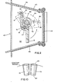
- the two-bladed wheel comprising a central hub 10 and a pair of blades 12 and 14 extending outwardly in parallel relation in opposite directions from the hub 10, from portions of the hub on opposite sides of the axis and spaced from the axis by an equal amount to provide a balanced wheel.
- the two-bladed wheel is mounted for movement about an axis by means of a bushing 16 which is received in fitting relation within an axial bore 18 through a portion of the hub and which, in turn, is mounted on the end of a motor driven shaft 20 which extends through an axial opening 22 in the hub in contiguous relation with the bore 18.
- the bushing is provided with a key 24 adapted to be received in fitting relationship within a keyway 26 in the hub for replaceably mounting the two-bladed wheel on the bushing for rotational movement therewith.
- each blade 12 and 14 is formed with a rib 30 which projects from the front face along the lower edge substantially throughout the length thereof.
- a similar rib 32 of lesser depth extends from the upper edge of the front face substantially throughout the length thereof except for a short inner section adjacent the hub 10 in circumferential alignment with the outlet from the feed tube through which particulate media flow into the path of the inner end portion of the blades for engagement thereby during rotational movement of the wheel.
- the two-bladed wheel is formed in one piece to enable easier assembly while providing a stronger wheel which remains well balanced -during use and thereby to provide for greater stability and less vibration during operation.
- the blades 12 and 14 are usually straight members of rectangular shape having a width within the range of 1.5-4 inches (3.81-10.2 cm) and a length within the range of 3-10 inches (7.62-25.4 cm).
- the ribs or flanges 30 and 32 operate to confine the particulate media for travel along the face of the blade and to minimize stray of particulate media over the edges of the blades.
- the two-bladed wheel is mounted within a shroud 40 having an open side 42 through which particulate media is projected by the wheel.
- the shroud is of trapezoidal shape with a back wall 44, angularly extending side walls 46 and 48 and trapezoidally shaped top and bottom walls 50 and 52.
- a bracket 54 mounts an electric motor 56 from the bottom wall 520fthe shroud with the shaft 20 of the motor extending through the bottom wall for receipt of the bushing 16 on the through extending portion thereof and which is adapted to be secured thereon, as by means of a cap screw 60.
- a rubber seal 62 is provided between the motor housing and the wall 52 of the shroud and a sealing gasket 64 is provided about the shaft portion extending through the wall 52 for protection from the abrasive media.
- one preferred configuration for the particulate feed means comprises a feed tube 66 which tapers inwardly from the entrance end 68 to the discharge end 70 with the discharge end defining an orifice of crescent shape arranged to extend circumferentially to the axis of rotation of the wheel or to extend lengthwise in the direction of rotation of the blade.
- a feed tube 66 of the type shown in Figure 9 in which the feed tube tapers inwardly from the inlet end 72 to the discharge end 74 with the outlet opening at the discharge end being of oblong or other geometric shape with the major dimension extending in the direction circumferentially of the axis or in the direction of rotation of the blade.
- the feed means can be formed of two or more separate tubular members 76 and 78 of circular or polygonal cross section, each of which tapers inwardly from their inlet end 80 to the discharge 82 with the tubular members arranged circumferentially with respect to the axis of the wheel to discharge particulate media at variable distances from the blade for continuous engagement by the blade over a period of time during its rotational movement.
- the feed tube 66 extends through an opening in the top plate of the shroud to a level immediately above the upper inner edge of the blade.
- the feed tube 66 is supported by a plate 84 that is fastened to the top wall 50 by means of lock washers 86 held down by cap screws 88.
- Particulate media is fed to the inlet of the feed tube 66 from a hopper (not shown) in communication therewith for gravity flow of particulate media from the hopper into the feed tube.
- the wheel In operation, the wheel is rotated at high speed.
- the article to be treated by particulate media thrown from the wheel is positioned in front of the open side 42 of the shroud.
- Particulate media which falls from the discharge end of the tube 66 is engaged by the face of the blades rotating at high speed.
- the particulate media Upon engagement with the face of the rotating blades, the particulate media is centrifugally displaced over the face of the blade and is thrown with high centrifugal force from the ends thereof, through the open side 42 onto the article in front thereof.
- the wheel shaft can be driven in rotational movement by convention means other than an electrical motor, for example, as by an internal combustion engine, magnetic drive, or by indirect belt or gear drive.
- the shroud can vary in shape as long as it substantially encloses the wheel except for the open side wall for projection of the particulate media therethrough.
- the wheel can be mounted for rotational movement about a vertical axis or a horizontal axis or any angle in between.
- the wheel assembly described constitutes a low cost airless blast device which is easy to operate and which utilizes minimum space and supporting equipment.
- the spent abrasive or other particulate media can be recovered in the usual manner for reuse, preferably after removing dust and dirt as by means of a screen, air wash, and/or magnetic separator.
- the described features are not restricted to a vertical feed to wheel blades mounted for rotational movement in a horizontal plane. It has been found that similar results can be obtained with a wheel mounted to rotate about a substantially horizontally disposed axis or along any angle between vertical and horizontal. It is required, however, to divert the vertical flow of particulate material from downward flow through the tubular member and through a hollow member which extends crosswise and which includes the concept of decreasing cross sections to a discharge opening of the type described which faces laterally in the direction towards the adjacent outer edge of the blades to feed the particulate material onto the blades in circular alignment with the inner end portions of the blades.
- Figures 11 and 12 illustrate a two-bladed wheel of the latter type mounted for rotational movement of the wheel about a horizontal axis for rotation of the blades in a vertical plane.
- the blades 12, 14 extend radially outwardly from the hub 10, are mounted on shaft 20 for rotational movement by the electrical driving motor 56 about their horizontal axis.
- the angle of the wheel can be varied for rotation about a . vertical or horizontal axis or any angle therebetween.
- the particulate material is fed into the funnel 100 which directs the particulate material into the open end 104 of a feed tube 102, in the form of a tubular member having a circular opening 106 in the inner side wall in crosswise alignment and in full communication with an outer open end 108 of a conically shaped hollow body 110 having a discharge opening 112 at its inner apex end in facing relation with the blades 14. At least a portion of the hollow body 110 leading into the discharge opening is of the diminishing cross section, as heretofore described for maintaining uniform flow and control of the particulate material fed onto the blades 12, 14.
- the discharge opening 112 is of a configuration of the type heretofore described to prolong the feed of particulate material onto the inner end portions of the blades 12, 14.
- the blades 12, 14 engage successive portions of the particulate material issuing from the feed opening 112 during rotational movement of the blades 12, 14 thereby to enlarge the pattern of particulate material projected from the ends of the blades.
- the various shapes of the feed openings elongated in the direction of rotational movement of the blades are illustrated in Figures 8, 9 and 10.
- the conically shaped hollow body 110 is preferably mounted on the tubular member for rotational adjustment relative thereto about an axis substantially in alignment with the axis of the wheel with the outlet opening 112 offset for crosswise alignment with the inner end portions of the blades 12, 14 to feed the particulate material onto the inner end portions of the blades 12, 14.
- the conically shaped hollow body 110 can be adjusted for rotational movement about its axis to locate the feed opening 112 in any desired circumferential relation relative to the wheel thereby to enable substantially precise control over the direction of the particulate material thrown from the ends of the blades 12, 14.
- the conically shaped hollow body when the conically shaped hollow body is rotated to position the feed opening 112 at the location shown in Figure 12, the particulate material will be thrown in a spread pattern in a lateral direction.
- the pattern of particulate material thrown from the ends of the blades 12, 14 will be in a downward direction.
- the hollow body 110 can be rotated to vary the direction which will normally be in a direction about diametrically opposite the radial direction of offset of the feed opening 112 from the axis of the wheel.
- the outlet opening 106 of the tubular member 102 and the inlet opening 108 of the hollow body 110 are formed of circular cross section with an annular flange 114 about the inlet in telescoping relation with an annular shroud 116 about the outlet opening 106 to support the hollow body 110 on the tubular member 102.
- the telescoping portions can be provided with openings (not shown) through which locking pins (not shown) can be inserted when aligned to interlock the members in their assembled and adjusted relation.
- the elements may be secured in the assembled relation by suitable clamps or other locking means.
Landscapes
- Engineering & Computer Science (AREA)
- Mechanical Engineering (AREA)
- Crushing And Pulverization Processes (AREA)
Claims (10)
Priority Applications (2)
| Application Number | Priority Date | Filing Date | Title |
|---|---|---|---|
| DE8080301825T DE3070266D1 (en) | 1980-06-02 | 1980-06-02 | Airless centrifugal blast device |
| EP80301825A EP0041086B1 (de) | 1980-06-02 | 1980-06-02 | Schleuderstrahlvorrichtung |
Applications Claiming Priority (1)
| Application Number | Priority Date | Filing Date | Title |
|---|---|---|---|
| EP80301825A EP0041086B1 (de) | 1980-06-02 | 1980-06-02 | Schleuderstrahlvorrichtung |
Publications (2)
| Publication Number | Publication Date |
|---|---|
| EP0041086A1 EP0041086A1 (de) | 1981-12-09 |
| EP0041086B1 true EP0041086B1 (de) | 1985-03-13 |
Family
ID=8187182
Family Applications (1)
| Application Number | Title | Priority Date | Filing Date |
|---|---|---|---|
| EP80301825A Expired EP0041086B1 (de) | 1980-06-02 | 1980-06-02 | Schleuderstrahlvorrichtung |
Country Status (2)
| Country | Link |
|---|---|
| EP (1) | EP0041086B1 (de) |
| DE (1) | DE3070266D1 (de) |
Families Citing this family (1)
| Publication number | Priority date | Publication date | Assignee | Title |
|---|---|---|---|---|
| FI72907C (fi) * | 1984-07-06 | 1987-08-10 | Tampella Oy Ab | Anordning foer rengoering av arbetsstyckets yta med rengoeringspartiklar. |
Citations (7)
| Publication number | Priority date | Publication date | Assignee | Title |
|---|---|---|---|---|
| CH117608A (de) * | 1925-08-20 | 1926-11-16 | Rudolf Geiger | Sandschleudermaschine. |
| US2131143A (en) * | 1935-09-23 | 1938-09-27 | Horace B Fay | Abrasive projecting apparatus |
| US2204637A (en) * | 1938-06-09 | 1940-06-18 | American Foundry Equip Co | Abrasive projecting machine |
| US2295926A (en) * | 1938-08-03 | 1942-09-15 | W W Sly Mfg Company | Abrasive throwing machine |
| US2363437A (en) * | 1943-06-14 | 1944-11-21 | Rolland E Peterson | Centrifugal blasting machine |
| DE1673091U (de) * | 1953-12-17 | 1954-03-04 | Badische Maschinenfabrik A G S | Schleuderrad zum putzen von guss- und stahlwerkserzeugnissen, zum mattieren von glas od. dgl. |
| CH446944A (de) * | 1965-07-19 | 1968-03-15 | Giessereianlagen Veb | Schleudervorrichtung für Putz- oder Entzunderungsmaschinen |
Family Cites Families (1)
| Publication number | Priority date | Publication date | Assignee | Title |
|---|---|---|---|---|
| CH207111A (de) * | 1938-11-04 | 1939-09-30 | Grocholl Karl | Schleudervorrichtung für Körniges Gut, für Putz- und entzunderungsanlagen. |
-
1980
- 1980-06-02 EP EP80301825A patent/EP0041086B1/de not_active Expired
- 1980-06-02 DE DE8080301825T patent/DE3070266D1/de not_active Expired
Patent Citations (7)
| Publication number | Priority date | Publication date | Assignee | Title |
|---|---|---|---|---|
| CH117608A (de) * | 1925-08-20 | 1926-11-16 | Rudolf Geiger | Sandschleudermaschine. |
| US2131143A (en) * | 1935-09-23 | 1938-09-27 | Horace B Fay | Abrasive projecting apparatus |
| US2204637A (en) * | 1938-06-09 | 1940-06-18 | American Foundry Equip Co | Abrasive projecting machine |
| US2295926A (en) * | 1938-08-03 | 1942-09-15 | W W Sly Mfg Company | Abrasive throwing machine |
| US2363437A (en) * | 1943-06-14 | 1944-11-21 | Rolland E Peterson | Centrifugal blasting machine |
| DE1673091U (de) * | 1953-12-17 | 1954-03-04 | Badische Maschinenfabrik A G S | Schleuderrad zum putzen von guss- und stahlwerkserzeugnissen, zum mattieren von glas od. dgl. |
| CH446944A (de) * | 1965-07-19 | 1968-03-15 | Giessereianlagen Veb | Schleudervorrichtung für Putz- oder Entzunderungsmaschinen |
Also Published As
| Publication number | Publication date |
|---|---|
| DE3070266D1 (en) | 1985-04-18 |
| EP0041086A1 (de) | 1981-12-09 |
Similar Documents
| Publication | Publication Date | Title |
|---|---|---|
| US4333278A (en) | Bladed centrifugal blasting wheel | |
| EP2501522B1 (de) | Vorrichtung mit einer schleuderradvorrichtung | |
| US4126280A (en) | Impact crusher | |
| CA1091646A (en) | Fluid entrained surface impacting comminuter and mixer | |
| US3888426A (en) | Machine and method for comminuting products | |
| US4329819A (en) | Centrifugal blasting apparatus | |
| US4480413A (en) | Bladed centrifugal blasting wheel | |
| EP0041086B1 (de) | Schleuderstrahlvorrichtung | |
| EP0210729B1 (de) | Sichter zum Sortieren von Materialpartikeln | |
| US2295926A (en) | Abrasive throwing machine | |
| US2204635A (en) | Centrifugal abrading machine | |
| US4378662A (en) | Airless centrifugal blast device | |
| US2254234A (en) | Abrasive equipment | |
| US4941297A (en) | Flared vane for abrasive blasting wheel | |
| CA1119812A (en) | Airless centrifugal blast device | |
| CA1313311C (en) | Abrading apparatus and process for making the same | |
| EP0518102B1 (de) | Schleuderstrahlvorrichtung | |
| USRE20538E (en) | Abrasive throwing machine | |
| US2108005A (en) | Abrading apparatus | |
| US2204587A (en) | Centrifugal abrasive blasting machine | |
| CA1242586A (en) | Flared vane for abrasive blasting wheel | |
| KR850000007B1 (ko) | 원심 송풍장치 | |
| JPS6014671B2 (ja) | 粒状材料による無気噴射加工装置 | |
| JPS58181573A (ja) | 遠心投射機のインペラ−装置 | |
| US2162139A (en) | Centrifugal abrasive projecting machine |
Legal Events
| Date | Code | Title | Description |
|---|---|---|---|
| PUAI | Public reference made under article 153(3) epc to a published international application that has entered the european phase |
Free format text: ORIGINAL CODE: 0009012 |
|
| AK | Designated contracting states |
Designated state(s): BE CH DE FR GB |
|
| 17P | Request for examination filed |
Effective date: 19820504 |
|
| GRAA | (expected) grant |
Free format text: ORIGINAL CODE: 0009210 |
|
| AK | Designated contracting states |
Designated state(s): BE CH DE FR GB LI |
|
| REF | Corresponds to: |
Ref document number: 3070266 Country of ref document: DE Date of ref document: 19850418 |
|
| ET | Fr: translation filed | ||
| PLBE | No opposition filed within time limit |
Free format text: ORIGINAL CODE: 0009261 |
|
| STAA | Information on the status of an ep patent application or granted ep patent |
Free format text: STATUS: NO OPPOSITION FILED WITHIN TIME LIMIT |
|
| PG25 | Lapsed in a contracting state [announced via postgrant information from national office to epo] |
Ref country code: DE Effective date: 19860303 |
|
| 26N | No opposition filed | ||
| PG25 | Lapsed in a contracting state [announced via postgrant information from national office to epo] |
Ref country code: LI Effective date: 19860630 Ref country code: CH Effective date: 19860630 Ref country code: BE Effective date: 19860630 |
|
| BERE | Be: lapsed |
Owner name: WHEELABRATOR-FRYE INC. Effective date: 19860630 |
|
| PG25 | Lapsed in a contracting state [announced via postgrant information from national office to epo] |
Ref country code: FR Free format text: LAPSE BECAUSE OF NON-PAYMENT OF DUE FEES Effective date: 19870227 |
|
| REG | Reference to a national code |
Ref country code: CH Ref legal event code: PL |
|
| GBPC | Gb: european patent ceased through non-payment of renewal fee | ||
| REG | Reference to a national code |
Ref country code: FR Ref legal event code: ST |
|
| PG25 | Lapsed in a contracting state [announced via postgrant information from national office to epo] |
Ref country code: GB Effective date: 19881118 |