EP0041156A2 - Chauffe-eau - Google Patents
Chauffe-eau Download PDFInfo
- Publication number
- EP0041156A2 EP0041156A2 EP81103630A EP81103630A EP0041156A2 EP 0041156 A2 EP0041156 A2 EP 0041156A2 EP 81103630 A EP81103630 A EP 81103630A EP 81103630 A EP81103630 A EP 81103630A EP 0041156 A2 EP0041156 A2 EP 0041156A2
- Authority
- EP
- European Patent Office
- Prior art keywords
- boiler
- rotating body
- hollow rotating
- fuel
- inlet
- Prior art date
- Legal status (The legal status is an assumption and is not a legal conclusion. Google has not performed a legal analysis and makes no representation as to the accuracy of the status listed.)
- Withdrawn
Links
Images
Classifications
-
- F—MECHANICAL ENGINEERING; LIGHTING; HEATING; WEAPONS; BLASTING
- F23—COMBUSTION APPARATUS; COMBUSTION PROCESSES
- F23K—FEEDING FUEL TO COMBUSTION APPARATUS
- F23K3/00—Feeding or distributing of lump or pulverulent fuel to combustion apparatus
- F23K3/22—Controlling thickness of fuel bed
-
- F—MECHANICAL ENGINEERING; LIGHTING; HEATING; WEAPONS; BLASTING
- F23—COMBUSTION APPARATUS; COMBUSTION PROCESSES
- F23K—FEEDING FUEL TO COMBUSTION APPARATUS
- F23K3/00—Feeding or distributing of lump or pulverulent fuel to combustion apparatus
- F23K3/16—Over-feed arrangements
Definitions
- the invention relates to a boiler for coal according to the preamble of claim 1.
- the fuel reservoir as a whole is part of the boiler and is formed by a space within the boiler jacket.
- This fuel reservoir is connected to the combustion chamber via a passage slot for the fuel, the slot height of which can be regulated by means of a metering slide which can be moved up and down.
- the invention has for its object to provide a boiler that can be supplied with fuel in a particularly simple manner from an external main fuel storage container or the like. Forth, can be operated reliably with different fuels and, in terms of combustion technology, can cause congestion in the boiler Avoids fuel run-on and can also be used for domestic fire purposes if the fire protection system is in good condition.
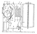
- the boiler 1 shown has a boiler jacket 2 through which water flows, the walls of which delimit a combustion chamber 3 which can be fed from an external fuel storage container or the like which is not shown and which extends essentially over the boiler depth.
- the combustion chamber 3 is delimited on the underside by an ash support plate 4, which can also have water flowing through it.
- a slag slide 5 is arranged closely above it, which can be moved to the left in the drawing by means of a drive mechanism 6 from its initial position shown.
- the ash support plate 4 and the slag slide 5 extend practically over the entire depth of the combustion chamber 3.
- the boiler 1 there is also a flue gas collecting space 7, to which secondary heating surfaces in the form of water pockets 8 can be assigned.
- an inlet connection 11 which also extends approximately over the boiler depth, is arranged in the left side of the boiler wall above the combustion chamber 3 and penetrates a corresponding recess in the side wall of the boiler.
- a guide wall 12 offset downwards for a fuel layer migrating to the ember bed on the ash support plate 4.
- the height of the layer is limited by a metering slide 14 which is arranged above the guide wall 12 and which defines a through-slot 13, which is guided along guides 15 and whose distance from the guide wall 12 can be adjusted by means of a drive rod 16.
- the inlet connector 11 is provided with an external peripheral connection flange 17 which is intended for simple connection of the inlet connector 11 to an inlet channel 19, not shown, which establishes the connection with the main fuel storage container.
- a metering and fire protection lock 18 is arranged in a free space forming a built-in intermediate storage space above the guide wall 12, which comprises a hollow rotating body 19 with a drum shell 20 closed at the end, which has an axial inlet and outlet slot 21 over its entire length.
- the hollow rotating body 19 can be rotated by a motorized drive, not shown, for a full revolution from its illustrated starting position, in which the inlet and outlet slot 21 faces the inlet connector 11, the lower longitudinal edge of the slot running close to and along the bottom edge of the inlet connector 11.
- the hollow rotating body 19, which in its starting position is filled with fuel from the inlet connection 11, reaches a position in which the amount of fuel contained in it falls out into the corner region between the metering slide 14 and the guide wall 12, while the drum jacket 20 takes the fuel wake out of the inlet connection 11 locks.
- Behind the metering and fire protection lock 18 is e.g. Level indicator designed as a pivot sensor 22 is provided, which forms a switching device for driving the hollow rotating body 19.
- the swivel sensor is arranged behind the metering slide in the example shown, but can also be found in front of this arrangement. If the swivel sensor 22 is no longer swiveled out by fuel and it can therefore move into its downward-facing position, it sets the drive for the hollow rotating body 19 into operation for one revolution each. This process can be repeated until the pivot sensor 22 has reached the pivoted-out position by fuel in which it switches off the drive.
- the slag slide 5 can also experience a working movement in the drawing a little to the left, this working stroke being repeated several times, for example in accordance with the number of revolutions of the hollow rotating body 19.
- a bar 23 on the free longitudinal edge of the ash support plate 4 in the ash box this bar 23 being a light one Has a slope and defines a break-off edge for the slag on its outer longitudinal edge.
- the inlet connector can also open into the free space from the boiler cover wall, which then extends up to the boiler cover wall and has a somewhat larger intermediate storage volume.
- the starting position of the hollow rotating body for the rotation is arbitrary, but preferably also such that the inlet and outlet slots face the inlet connector.
Landscapes
- Engineering & Computer Science (AREA)
- Chemical & Material Sciences (AREA)
- Combustion & Propulsion (AREA)
- Mechanical Engineering (AREA)
- General Engineering & Computer Science (AREA)
- Solid-Fuel Combustion (AREA)
- Feeding And Controlling Fuel (AREA)
Applications Claiming Priority (2)
| Application Number | Priority Date | Filing Date | Title |
|---|---|---|---|
| DE19803020324 DE3020324A1 (de) | 1980-05-29 | 1980-05-29 | Heizkessel |
| DE3020324 | 1980-05-29 |
Publications (2)
| Publication Number | Publication Date |
|---|---|
| EP0041156A2 true EP0041156A2 (fr) | 1981-12-09 |
| EP0041156A3 EP0041156A3 (fr) | 1982-01-27 |
Family
ID=6103460
Family Applications (1)
| Application Number | Title | Priority Date | Filing Date |
|---|---|---|---|
| EP81103630A Withdrawn EP0041156A3 (fr) | 1980-05-29 | 1981-05-12 | Chauffe-eau |
Country Status (2)
| Country | Link |
|---|---|
| EP (1) | EP0041156A3 (fr) |
| DE (1) | DE3020324A1 (fr) |
Cited By (2)
| Publication number | Priority date | Publication date | Assignee | Title |
|---|---|---|---|---|
| EP0245173A1 (fr) * | 1986-05-07 | 1987-11-11 | CHARBONNAGES DE FRANCE, Etablissement public dit: | Dispositif de sécurité automatique pour chaudière à grille mécanique utilisant un combustible solide |
| WO2009021255A3 (fr) * | 2007-08-14 | 2009-07-16 | Peter Winkler | Dispositif de combustion d'éléments combustibles solides |
Families Citing this family (1)
| Publication number | Priority date | Publication date | Assignee | Title |
|---|---|---|---|---|
| CN104930536A (zh) * | 2015-05-26 | 2015-09-23 | 德清赛众换热器制造有限公司 | 一种一体式生物燃料壁炉的进料斗结构 |
Family Cites Families (8)
| Publication number | Priority date | Publication date | Assignee | Title |
|---|---|---|---|---|
| FR444584A (fr) * | 1912-06-04 | 1912-10-21 | Franz Ekl | Foyer fumivore à chargement mécanique de la grille |
| FR781237A (fr) * | 1934-11-14 | 1935-05-11 | Cie Parisienne De Distrib De C | Chargeur-conducteur automatique de chaudières pour chauffage central |
| US2438407A (en) * | 1944-04-13 | 1948-03-23 | John A Kreuser | Heating plant and furnace |
| GB728650A (en) * | 1953-12-17 | 1955-04-20 | Johannes Martinus Haslinghuis | A plant for stoking shavings, chips or similar light and inflammable waste |
| AT208558B (de) * | 1958-10-03 | 1960-04-11 | Jan Severa | Kombinierte Rost- und Schachtfeuerung für gußeiserne Zentralheizungs - Gliederkessel |
| FR1357072A (fr) * | 1963-02-21 | 1964-04-03 | Perfectionnement aux chaudières à charbon à alimentation automatique | |
| DE1556614B1 (de) * | 1968-02-14 | 1970-04-02 | Peter Langen | Anlage zur Beschickung von Kesseln mit fein- und grobstueckiger Kohle |
| AT316718B (de) * | 1971-11-09 | 1974-07-25 | Fritz Mielacher | Einrichtung an Säge- oder Hobelspanfeuerungsanlagen |
-
1980
- 1980-05-29 DE DE19803020324 patent/DE3020324A1/de not_active Ceased
-
1981
- 1981-05-12 EP EP81103630A patent/EP0041156A3/fr not_active Withdrawn
Cited By (3)
| Publication number | Priority date | Publication date | Assignee | Title |
|---|---|---|---|---|
| EP0245173A1 (fr) * | 1986-05-07 | 1987-11-11 | CHARBONNAGES DE FRANCE, Etablissement public dit: | Dispositif de sécurité automatique pour chaudière à grille mécanique utilisant un combustible solide |
| FR2598489A1 (fr) * | 1986-05-07 | 1987-11-13 | Charbonnages De France | Dispositif de securite automatique pour chaudiere a grille mecanique utilisant un combustible solide |
| WO2009021255A3 (fr) * | 2007-08-14 | 2009-07-16 | Peter Winkler | Dispositif de combustion d'éléments combustibles solides |
Also Published As
| Publication number | Publication date |
|---|---|
| EP0041156A3 (fr) | 1982-01-27 |
| DE3020324A1 (de) | 1981-12-03 |
Similar Documents
| Publication | Publication Date | Title |
|---|---|---|
| DE69101692T2 (de) | Aquarienfilter. | |
| DE3212316C2 (de) | Filtrationsapparat | |
| DE7633758U1 (de) | Ofen | |
| DE2732119A1 (de) | Dampfbuegeleisen | |
| DE3540164A1 (de) | Filtervorrichtung fuer die neutralisation saurer kondensate aus abgasen | |
| EP0673601A1 (fr) | Filtre pour aquariums | |
| EP0041156A2 (fr) | Chauffe-eau | |
| DE69405894T2 (de) | Schirm für Aquarium-Behälter | |
| DE2356062C3 (de) | Elektrisches Dampfbügeleisen | |
| DE2612255A1 (de) | Verfahren und anlage zur reinigung von abwasser nach dem belebtschlammverfahren | |
| DE3127268A1 (de) | "vorrichtung zum austauschen des wassers in aquarien" | |
| DE3915190C2 (fr) | ||
| DE659784C (de) | Vorrichtung zum Entaschen und Entschlacken von Fahrzeuggaserzeugern | |
| EP0016999B1 (fr) | Dispositif de filtrage biologique pour aquariums | |
| AT346033B (de) | Fuellschachtverbrennungsanlage | |
| DE3137522A1 (de) | "grillgeraet" | |
| DE503217C (de) | Drehrost-Gaserzeuger mit Wasserverschluss und Einfuehrung der Vergasungsluft durch das Wasser der Aschenschuessel | |
| DE20682C (de) | Neuerungen an Dampfmotoren mit eigenartiger Steuerung und Speisevorrichtung | |
| DE3443761A1 (de) | Zum vermischen von warmwasser und kaltwasser dienendes mischventil | |
| DE393243C (de) | Vorrichtung fuer chemische Reaktionen aller Art | |
| DE637319C (de) | Filter, insbesondere fuer Kesselspeisewasser | |
| DE412830C (de) | Vorrichtung zur Reinigung von Generatorgasen | |
| DE876132C (de) | Vorrichtung zum Anzuenden und Anfachen von Gaserzeugern, insbesondere fuer Kraftfahrzeuge | |
| DE2640114B2 (de) | Anlage für die Zucht von Pflanzen in mit einer Flüssigkeit berieselten Behältern | |
| DE2801544B2 (de) | Einrichtung zur Kühlung von körnigem oder staubförmigem Gut |
Legal Events
| Date | Code | Title | Description |
|---|---|---|---|
| PUAI | Public reference made under article 153(3) epc to a published international application that has entered the european phase |
Free format text: ORIGINAL CODE: 0009012 |
|
| PUAL | Search report despatched |
Free format text: ORIGINAL CODE: 0009013 |
|
| AK | Designated contracting states |
Designated state(s): AT BE CH DE FR GB IT NL SE |
|
| AK | Designated contracting states |
Designated state(s): AT BE CH DE FR GB IT NL SE |
|
| STAA | Information on the status of an ep patent application or granted ep patent |
Free format text: STATUS: THE APPLICATION IS DEEMED TO BE WITHDRAWN |
|
| 18D | Application deemed to be withdrawn |
Effective date: 19830103 |
|
| RIN1 | Information on inventor provided before grant (corrected) |
Inventor name: SCHALLENBERG, EMIL |