EP0041285A2 - Sicherheitsvorrichtung für den Brenner einer Kohlevergasungsanlage - Google Patents
Sicherheitsvorrichtung für den Brenner einer Kohlevergasungsanlage Download PDFInfo
- Publication number
- EP0041285A2 EP0041285A2 EP81200521A EP81200521A EP0041285A2 EP 0041285 A2 EP0041285 A2 EP 0041285A2 EP 81200521 A EP81200521 A EP 81200521A EP 81200521 A EP81200521 A EP 81200521A EP 0041285 A2 EP0041285 A2 EP 0041285A2
- Authority
- EP
- European Patent Office
- Prior art keywords
- channel
- inlet
- safety device
- outlet
- fluid
- Prior art date
- Legal status (The legal status is an assumption and is not a legal conclusion. Google has not performed a legal analysis and makes no representation as to the accuracy of the status listed.)
- Granted
Links
- 239000003245 coal Substances 0.000 title claims abstract description 50
- 238000002309 gasification Methods 0.000 title claims abstract description 13
- 239000012530 fluid Substances 0.000 claims abstract description 51
- 239000002245 particle Substances 0.000 claims abstract description 42
- 239000000203 mixture Substances 0.000 claims abstract description 37
- 239000007787 solid Substances 0.000 abstract description 4
- 239000011343 solid material Substances 0.000 abstract 1
- 238000000034 method Methods 0.000 description 7
- IJGRMHOSHXDMSA-UHFFFAOYSA-N Atomic nitrogen Chemical compound N#N IJGRMHOSHXDMSA-UHFFFAOYSA-N 0.000 description 3
- 239000011362 coarse particle Substances 0.000 description 3
- 239000007789 gas Substances 0.000 description 2
- XLYOFNOQVPJJNP-UHFFFAOYSA-N water Substances O XLYOFNOQVPJJNP-UHFFFAOYSA-N 0.000 description 2
- QVGXLLKOCUKJST-UHFFFAOYSA-N atomic oxygen Chemical compound [O] QVGXLLKOCUKJST-UHFFFAOYSA-N 0.000 description 1
- 230000015572 biosynthetic process Effects 0.000 description 1
- 238000007664 blowing Methods 0.000 description 1
- 238000002485 combustion reaction Methods 0.000 description 1
- 239000007788 liquid Substances 0.000 description 1
- 229910052757 nitrogen Inorganic materials 0.000 description 1
- 231100000989 no adverse effect Toxicity 0.000 description 1
- 239000001301 oxygen Substances 0.000 description 1
- 229910052760 oxygen Inorganic materials 0.000 description 1
- 238000003786 synthesis reaction Methods 0.000 description 1
- 239000004753 textile Substances 0.000 description 1
Images


Classifications
-
- C—CHEMISTRY; METALLURGY
- C10—PETROLEUM, GAS OR COKE INDUSTRIES; TECHNICAL GASES CONTAINING CARBON MONOXIDE; FUELS; LUBRICANTS; PEAT
- C10J—PRODUCTION OF PRODUCER GAS, WATER-GAS, SYNTHESIS GAS FROM SOLID CARBONACEOUS MATERIAL, OR MIXTURES CONTAINING THESE GASES; CARBURETTING AIR OR OTHER GASES
- C10J3/00—Production of combustible gases containing carbon monoxide from solid carbonaceous fuels
- C10J3/46—Gasification of granular or pulverulent flues in suspension
- C10J3/48—Apparatus; Plants
- C10J3/50—Fuel charging devices
-
- B—PERFORMING OPERATIONS; TRANSPORTING
- B65—CONVEYING; PACKING; STORING; HANDLING THIN OR FILAMENTARY MATERIAL
- B65G—TRANSPORT OR STORAGE DEVICES, e.g. CONVEYORS FOR LOADING OR TIPPING, SHOP CONVEYOR SYSTEMS OR PNEUMATIC TUBE CONVEYORS
- B65G53/00—Conveying materials in bulk through troughs, pipes or tubes by floating the materials or by flow of gas, liquid or foam
- B65G53/34—Details
- B65G53/52—Adaptations of pipes or tubes
- B65G53/521—Adaptations of pipes or tubes means for preventing the accumulation or for removal of deposits
-
- C—CHEMISTRY; METALLURGY
- C10—PETROLEUM, GAS OR COKE INDUSTRIES; TECHNICAL GASES CONTAINING CARBON MONOXIDE; FUELS; LUBRICANTS; PEAT
- C10J—PRODUCTION OF PRODUCER GAS, WATER-GAS, SYNTHESIS GAS FROM SOLID CARBONACEOUS MATERIAL, OR MIXTURES CONTAINING THESE GASES; CARBURETTING AIR OR OTHER GASES
- C10J3/00—Production of combustible gases containing carbon monoxide from solid carbonaceous fuels
- C10J3/02—Fixed-bed gasification of lump fuel
- C10J3/20—Apparatus; Plants
- C10J3/30—Fuel charging devices
-
- C—CHEMISTRY; METALLURGY
- C10—PETROLEUM, GAS OR COKE INDUSTRIES; TECHNICAL GASES CONTAINING CARBON MONOXIDE; FUELS; LUBRICANTS; PEAT
- C10J—PRODUCTION OF PRODUCER GAS, WATER-GAS, SYNTHESIS GAS FROM SOLID CARBONACEOUS MATERIAL, OR MIXTURES CONTAINING THESE GASES; CARBURETTING AIR OR OTHER GASES
- C10J3/00—Production of combustible gases containing carbon monoxide from solid carbonaceous fuels
- C10J3/46—Gasification of granular or pulverulent flues in suspension
- C10J3/48—Apparatus; Plants
- C10J3/50—Fuel charging devices
- C10J3/506—Fuel charging devices for entrained flow gasifiers
-
- F—MECHANICAL ENGINEERING; LIGHTING; HEATING; WEAPONS; BLASTING
- F23—COMBUSTION APPARATUS; COMBUSTION PROCESSES
- F23K—FEEDING FUEL TO COMBUSTION APPARATUS
- F23K3/00—Feeding or distributing of lump or pulverulent fuel to combustion apparatus
- F23K3/02—Pneumatic feeding arrangements, i.e. by air blast
-
- C—CHEMISTRY; METALLURGY
- C10—PETROLEUM, GAS OR COKE INDUSTRIES; TECHNICAL GASES CONTAINING CARBON MONOXIDE; FUELS; LUBRICANTS; PEAT
- C10J—PRODUCTION OF PRODUCER GAS, WATER-GAS, SYNTHESIS GAS FROM SOLID CARBONACEOUS MATERIAL, OR MIXTURES CONTAINING THESE GASES; CARBURETTING AIR OR OTHER GASES
- C10J2200/00—Details of gasification apparatus
- C10J2200/36—Moving parts inside the gasification reactor not otherwise provided for
-
- C—CHEMISTRY; METALLURGY
- C10—PETROLEUM, GAS OR COKE INDUSTRIES; TECHNICAL GASES CONTAINING CARBON MONOXIDE; FUELS; LUBRICANTS; PEAT
- C10J—PRODUCTION OF PRODUCER GAS, WATER-GAS, SYNTHESIS GAS FROM SOLID CARBONACEOUS MATERIAL, OR MIXTURES CONTAINING THESE GASES; CARBURETTING AIR OR OTHER GASES
- C10J2300/00—Details of gasification processes
- C10J2300/09—Details of the feed, e.g. feeding of spent catalyst, inert gas or halogens
- C10J2300/0913—Carbonaceous raw material
- C10J2300/093—Coal
-
- C—CHEMISTRY; METALLURGY
- C10—PETROLEUM, GAS OR COKE INDUSTRIES; TECHNICAL GASES CONTAINING CARBON MONOXIDE; FUELS; LUBRICANTS; PEAT
- C10J—PRODUCTION OF PRODUCER GAS, WATER-GAS, SYNTHESIS GAS FROM SOLID CARBONACEOUS MATERIAL, OR MIXTURES CONTAINING THESE GASES; CARBURETTING AIR OR OTHER GASES
- C10J2300/00—Details of gasification processes
- C10J2300/09—Details of the feed, e.g. feeding of spent catalyst, inert gas or halogens
- C10J2300/0953—Gasifying agents
- C10J2300/0956—Air or oxygen enriched air
-
- C—CHEMISTRY; METALLURGY
- C10—PETROLEUM, GAS OR COKE INDUSTRIES; TECHNICAL GASES CONTAINING CARBON MONOXIDE; FUELS; LUBRICANTS; PEAT
- C10J—PRODUCTION OF PRODUCER GAS, WATER-GAS, SYNTHESIS GAS FROM SOLID CARBONACEOUS MATERIAL, OR MIXTURES CONTAINING THESE GASES; CARBURETTING AIR OR OTHER GASES
- C10J2300/00—Details of gasification processes
- C10J2300/09—Details of the feed, e.g. feeding of spent catalyst, inert gas or halogens
- C10J2300/0953—Gasifying agents
- C10J2300/0959—Oxygen
-
- C—CHEMISTRY; METALLURGY
- C10—PETROLEUM, GAS OR COKE INDUSTRIES; TECHNICAL GASES CONTAINING CARBON MONOXIDE; FUELS; LUBRICANTS; PEAT
- C10J—PRODUCTION OF PRODUCER GAS, WATER-GAS, SYNTHESIS GAS FROM SOLID CARBONACEOUS MATERIAL, OR MIXTURES CONTAINING THESE GASES; CARBURETTING AIR OR OTHER GASES
- C10J2300/00—Details of gasification processes
- C10J2300/09—Details of the feed, e.g. feeding of spent catalyst, inert gas or halogens
- C10J2300/0953—Gasifying agents
- C10J2300/0973—Water
- C10J2300/0976—Water as steam
-
- C—CHEMISTRY; METALLURGY
- C10—PETROLEUM, GAS OR COKE INDUSTRIES; TECHNICAL GASES CONTAINING CARBON MONOXIDE; FUELS; LUBRICANTS; PEAT
- C10J—PRODUCTION OF PRODUCER GAS, WATER-GAS, SYNTHESIS GAS FROM SOLID CARBONACEOUS MATERIAL, OR MIXTURES CONTAINING THESE GASES; CARBURETTING AIR OR OTHER GASES
- C10J2300/00—Details of gasification processes
- C10J2300/18—Details of the gasification process, e.g. loops, autothermal operation
- C10J2300/1807—Recycle loops, e.g. gas, solids, heating medium, water
- C10J2300/1823—Recycle loops, e.g. gas, solids, heating medium, water for synthesis gas
-
- Y—GENERAL TAGGING OF NEW TECHNOLOGICAL DEVELOPMENTS; GENERAL TAGGING OF CROSS-SECTIONAL TECHNOLOGIES SPANNING OVER SEVERAL SECTIONS OF THE IPC; TECHNICAL SUBJECTS COVERED BY FORMER USPC CROSS-REFERENCE ART COLLECTIONS [XRACs] AND DIGESTS
- Y10—TECHNICAL SUBJECTS COVERED BY FORMER USPC
- Y10T—TECHNICAL SUBJECTS COVERED BY FORMER US CLASSIFICATION
- Y10T137/00—Fluid handling
- Y10T137/4238—With cleaner, lubrication added to fluid or liquid sealing at valve interface
- Y10T137/4245—Cleaning or steam sterilizing
- Y10T137/4259—With separate material addition
-
- Y—GENERAL TAGGING OF NEW TECHNOLOGICAL DEVELOPMENTS; GENERAL TAGGING OF CROSS-SECTIONAL TECHNOLOGIES SPANNING OVER SEVERAL SECTIONS OF THE IPC; TECHNICAL SUBJECTS COVERED BY FORMER USPC CROSS-REFERENCE ART COLLECTIONS [XRACs] AND DIGESTS
- Y10—TECHNICAL SUBJECTS COVERED BY FORMER USPC
- Y10T—TECHNICAL SUBJECTS COVERED BY FORMER US CLASSIFICATION
- Y10T137/00—Fluid handling
- Y10T137/8593—Systems
- Y10T137/86493—Multi-way valve unit
- Y10T137/86558—Plural noncommunicating flow paths
-
- Y—GENERAL TAGGING OF NEW TECHNOLOGICAL DEVELOPMENTS; GENERAL TAGGING OF CROSS-SECTIONAL TECHNOLOGIES SPANNING OVER SEVERAL SECTIONS OF THE IPC; TECHNICAL SUBJECTS COVERED BY FORMER USPC CROSS-REFERENCE ART COLLECTIONS [XRACs] AND DIGESTS
- Y10—TECHNICAL SUBJECTS COVERED BY FORMER USPC
- Y10T—TECHNICAL SUBJECTS COVERED BY FORMER US CLASSIFICATION
- Y10T137/00—Fluid handling
- Y10T137/8593—Systems
- Y10T137/86493—Multi-way valve unit
- Y10T137/86558—Plural noncommunicating flow paths
- Y10T137/86566—Rotary plug
Definitions
- the invention relates to a safety device for protecting against blockage a burner of a coal gasification plant fed with a mixture of coal particles and fluid.
- the mixture of coal particles and fluid sometimes contains foreign solid particles having larger dimensions than those of the coal particles and than those of the passages of the burner.
- said foreign particles for example particles with a specific weight lower than that of the coal particles, non-ferro particles, textile particles, plastic particles, etc.
- Blockage of a burner causes serious disruptions of the coal gasification process and often necessitates disassembly of the blocked burner.
- the object of the invention is to provide a safety, device by means of which it is possible to prevent blockage of a burner of a coal gasification plant by said foreign particles.
- the safety device comprises an inlet and an outlet for the mixture of coal particles and fluid, an inlet and an outlet for a fluid for removing blockages, and a movable element provided with at least two channels, each channel consisting of a wide and a narrow part, wherein the channels and the inlets and outlets are so arranged that, in a certain position of the movable element, a channel forms a communication between the inlet and outlet for the mixture of coal particles and fluid, in such a way that in the direction from inlet to outlet the narrow part is located after the wide part of the channel, and that another channel forms a communication between the inlet and outlet for the fluid for removing blockages, in such a way that in the direction from inlet to outlet the wide part is located after the narrow part of the channel, wherein the movable element can be displaced from said position to another position so that one channel takes the place of another channel.
- the movable element is movably arranged in a housing.
- the movable element is rotatably arranged.
- the movable element is so arranged that it is linearly displaceable.
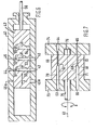
- a movable cylindrical element 2 is so arranged in a housing 1 that the element 2 is rotatable around its central longitudinal axis, as indicated by arrow A.
- the housing 1 is provided with an inlet 3 and an outlet 4 for the mixture of coal particles and fluid.
- the housing 1 is also provided with an inlet 5 and an outlet 6 for a fluid for removing blockages.
- two channels 7 and 8 are present, which channels 7 and 8 are parallel to each other and perpendicular to the central longitudinal axis of the element 2.
- the channel 7 connects the inlet 3 to the outlet 4 in such a manner that in the direction from inlet 3 to outlet 4, a narrow part 9 of the channel 7 is located after a wide part 10 of the channel 7.
- the channel 8 connects the inlet 5 to outlet 6 in such a manner that in the direction from inlet 5 to outlet 6 a wide part 11 of the channel 8 is located after a narrow part 12 of the channel 8.
- a movable element 22 is so arranged in a housing 21 that the element 22 is linearly displaceable in the direction of its longitudinal axis, as indicated by arrow B.
- the housing 21 is provided with an inlet 23 and an outlet 24 for the mixture of coal particles and fluid.
- the housing 21 is also provided with a double set of inlets 25 and 25a and outlets 26 and 26a for a fluid for removing blockages.
- two channels 27 and 28 are present.
- channel 27 connects inlet 23 to outlet 24 in such a way that, in the direction from inlet 23 to outlet 24, a narrow part 29 of channel 27 is located after a wide part 30 of channel 27.
- channel 28 connects inlet 25 to outlet 26 in such a way that, in the direction from inlet 25 to outlet 26, a wide part 31 of channel 28 is located after a narrow part 32 of channel 28.
- the channel 28 connects the inlet 23 to the outlet 24 and the channel 27 connects the inlet 25a to the outlet 26a.
- the narrow part 32 of the channel 28 is located after the wide part 31 of the channel 28 and, in the direction from inlet 25a to outlet 26a, the wide part 30 of the channel 27 is located after the narrow part 29 of the channel 27.
- one end of the element 22 is provided with a driving rod 33 passing through the wall of the housing 21.
- a movable element 42 is so arranged in a housing 41 that the element 42 is linearly displaceable in the direction of its longitudinal axis, as indicated by arrow C.
- the housing 41 is provided with an inlet 43 and an outlet 44 for the mixture of coal particles and fluid.
- the housing 41 is also provided with a double set of inlets 45 and 45a and outlets 46 and 46a for a fluid for removing blockages.
- the movable element 42 is provided with three channels 47, 48 and 49.
- the channel 47 connects the inlet 45a to the outlet 46a in such a way that, in the direction from inlet 45a to outlet 46a, a wide part 50 of channel 47 is located after a narrow part 51 of channel 47.
- the channel 48 connects the inlet 43 to the outlet 44 and the channel 49 connects the inlet 45 to the outlet 46.
- a narrow part 52 of channel 48 is located after a wide part 53 of channel 48 and, in the direction from inlet 45 to outlet 46, a wide part 54 of channel 49 is located after a narrow part 55 of channel 49.
- channel 49 has taken the place of channel 48 and channel 48 has taken the place of channel 47. In this position of element 42 channel 47 is out of operation.
- channel 47 has taken the place of channel 48 and channel 48 has taken the place of channel 49. In this position of the element 42 channel 49 is out of operation.
- one end of element 42 is provided with a driving rod 56 passing through the wall of the housing 41.
- a movable cylindrical element 61 is rotatably connected to a first body 73 by a shaft 75 and to a second body 74 by a pivot 76, so that the cylindrical element 61 is rotatable around its central longitudinal axis 62 relative to the bodies 73 and 74 in the directions as indicated by arrow D.
- the cylindrical element 61 is provided with two channels 67 and 68 which are parallel to the central axis 62.
- the first body 73 is provided with an inlet 63 for the mixture - of coal particles and fluid and with an outlet 66 for the fluid for removing blockages.
- the second body 74 is provided with an outlet 64 for the mixture of coal particles and fluid and with an inlet 65 for the fluid for removing blockages.
- the channel 67 connects the inlet 63 to the outlet 64 in such a manner that in the direction from inlet 63 to outlet 64, a narrow part 69 of the channel 67 is located after a wide part 70 of the channel 67.
- the channel 68 connects the inlet 65 to the outlet 66 in such a manner that in the direction from inlet 65 to outlet 66 a wide part 71 of the channel 68 is located after a narrow part 72 of the channel 68.
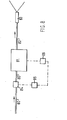
- reference numeral 80 indicates a line for feeding the mixture of coal particles and fluid to a safety device 81 of the kind as described hereinbefore. From the safety device 81 extends a line 82 for the mixture of coal particles and fluid to a burner 83 of a coal gasification plant (not shown).
- a flow meter 84 is arranged in the line 80 for determining the flow rate of the mixture of coal particles and fluid in the line 80.
- This flow meter 84 is connected to a controller 85 that is connected in turn to a servomotor 86 which is capable of adjusting the movable element of the safety device.
- the flow meter 84 is arranged in line 80. In an alternative arrangement (not shown), the flow meter may be placed in line 82, if desired.
- the operation of the system according to figure 8 is as follows: Assume that the safety device 81 used, is the embodiment according to figure 1.
- the line 80 is then connected to the inlet 3 and the line 82 to the outlet 4. If there are no coarse particles in the mixture of coal particles and fluid, the mixture will freely flow to the burner 83 through line 80, channel 7 and line 82. If coarse particles are present in said mixture, they will completely or partly block the narrow part 9 of the channel 7, with the result that the flow meter 84 indicates a fall in the passing quantity of mixture.
- the flow meter 84 then issues a signal to the controller 85 which compares the signal with a predetermined desired value.
- a signal is passed to the servomotor 86, which adjusts the movable element 2 of the safety device 81 in such a way that channels 7 and 8 interchange places. Since the clean, i.e. the non-blocked, channel 8 now forms the connection between inlet 3 and outlet 4, the mixture of coal particles and fluid can again freely flow to the burner 83.
- the blocked channel 7, which now forms the connection between inlet 5 and outlet 6, can now be blown out, since inlet 5 is connected to a line (not shown) supplying pressurized fluid that removes the blockage from the narrow part 9 and entrains it through the wide part 10 and through the outlet 6.
- a blockage occurs in the channel 8, which is now located between inlet 3 and outlet 4, the above-mentioned process is repeated, i.e. the channels 7 and 8 again interchange places.
- the line 80 is connected to the inlet 23 and the line 82 is connected to the outlet 24.
- the mixture of coal particles and fluid then flows to the burner 83 through line 80, channel 27 and line 82 (see figure 2).
- the element 22 is displaced to the position as shown in figure 3 by the servomotor 86.
- the clean, non-blocked channel 28 then takes the place of the blocked channel 27 and the channel 27 is then located between the inlet 25a and the outlet 26a. In this position of the element 22, the mixture of coal particles and fluid can freely flow to the burner 83, namely through line 80, channel 28 and line 82.
- inlet 25a is connected to a line (not shown) supplying pressurized fluid
- the blockage in the narrow part 29 of channel 27 will be entrained by the fluid and be discharged through the wide part 30 and the outlet 26a.
- the element 22 is returned to the position according to figure 2 by servomotor 86.
- the blown- out channel 27 is then again between inlet 23 and outlet 24, so that the mixture of coal particles and fluid can again freely flow to the burner 83, and the blocked channel 28 is then located between the inlet 25 and the outlet 26.
- the safety device 81 used is the embodiment according to figures 4, 5 and 6, line 80 is connected to the inlet 43 and line 82 is connected to the outlet 44.
- the mixture of coal particles and fluid then flows to the burner 83 through line 80, channel 48 and line 82 (see figure 4).
- the servomotor 86 displaces the movable element 42 either to the position according to figure 5 or to that according " to figure 6.
- the non-blocked channel 49 takes the place of channel 48
- the non-blocked channel 47 takes the place of channel 48.
- the mixture of coal particles and fluid can again freely flow to the burner.
- channel 48 Since both the inlet 45 and the inlet 45a are connected to a line supplying pressurized fluid, channel 48 will be blown out, both in the position according to figure 5 and in the position according to figure 6.
- the element 42 can be returned to the position according to figure 4, after which the whole process is repeated.
- line 80 is connected to the inlet 63 and line 82 to the outlet 64. If there are no coarse particles in the mixture of coal particles and fluid, the mixture will freely flow through line 80, inlet 63, channel 67, outlet 64 and line 82 to the burner . 83. As soon as a blockage occurs in the narrow part 69 of the channel 67, the servomotor 86 rotates the movable element 61 of the safety device 81 in such a way that the channels 67 and 68 interchange places. Since the non-blocked channel 68 now forms the connection between inlet 63 and outlet 64, the mixture of coal particles and fluid can again freely flow to the burner 83.
- the blocked channel 67 which now forms the connection between inlet 65 and outlet 66, can now be blown out, since inlet 65.is connected to a line (not shown) supplying pressurized fluid that removes the blockage from the narrow part 69 and entrains it through the wide part 70 and through the outlet 66.
- a blockage occurs in channel 68, which is now located between inlet 63 and outlet 64, the above-mentioned process is repeated, so that the channels 67 and 68 again interchange places.
- the diameters of the narrow parts 9, 12, 29, 32, 51, 52, 55, 69 and 72 of the respective channels 7, 8, 27, 28, 47, 48, 49, 67 and 68 are smaller than the diameters of the burner passages, so that it is ensured that the safety device will not allow the passage of particles that could block the burner passages.
- the fluid used in the mixture of coal particles and fluid is, for example, a gas such as nitrogen (N 2 ), synthesis gas (CO + H 2 ) or steam.
- the fluid used in the mixture of coal particles and fluid can also be a liquid, for example oil, water or a mixture of water and oil.
- the fluid used for blowing out the channels in the movable element is, for example, air or nitrogen.
- each burner is provided with an appertaining safety device as described in the above.
Landscapes
- Chemical & Material Sciences (AREA)
- Engineering & Computer Science (AREA)
- Combustion & Propulsion (AREA)
- Oil, Petroleum & Natural Gas (AREA)
- Organic Chemistry (AREA)
- Mechanical Engineering (AREA)
- General Engineering & Computer Science (AREA)
- Feeding And Controlling Fuel (AREA)
Applications Claiming Priority (2)
| Application Number | Priority Date | Filing Date | Title |
|---|---|---|---|
| NL8003093 | 1980-05-29 | ||
| NL8003093 | 1980-05-29 |
Publications (3)
| Publication Number | Publication Date |
|---|---|
| EP0041285A2 true EP0041285A2 (de) | 1981-12-09 |
| EP0041285A3 EP0041285A3 (en) | 1982-03-17 |
| EP0041285B1 EP0041285B1 (de) | 1984-01-25 |
Family
ID=19835377
Family Applications (1)
| Application Number | Title | Priority Date | Filing Date |
|---|---|---|---|
| EP81200521A Expired EP0041285B1 (de) | 1980-05-29 | 1981-05-14 | Sicherheitsvorrichtung für den Brenner einer Kohlevergasungsanlage |
Country Status (6)
| Country | Link |
|---|---|
| US (1) | US4365563A (de) |
| EP (1) | EP0041285B1 (de) |
| JP (1) | JPS5728904A (de) |
| CA (1) | CA1168049A (de) |
| DE (1) | DE3162015D1 (de) |
| ZA (1) | ZA813596B (de) |
Cited By (1)
| Publication number | Priority date | Publication date | Assignee | Title |
|---|---|---|---|---|
| FR2610657A1 (fr) * | 1987-02-07 | 1988-08-12 | Hochtief Ag Hoch Tiefbauten | Dispositif pour l'application d'une couche de beton projete |
Families Citing this family (11)
| Publication number | Priority date | Publication date | Assignee | Title |
|---|---|---|---|---|
| AU3066684A (en) * | 1983-06-24 | 1985-01-25 | Ruhrkohle Aktiengesellschaft | Sampling valve for a coal gasification plant with fly ash or fluidization pressure reactor |
| US4602657A (en) * | 1985-02-11 | 1986-07-29 | Anderson-Greenwood & Co. | Valve manifold for a differential pressure transmitter |
| US4676435A (en) * | 1986-04-01 | 1987-06-30 | Nesland Nickolas B | Sprayer head |
| JPS63103951A (ja) * | 1986-10-20 | 1988-05-09 | Nec Yamagata Ltd | ゴミ検査装置 |
| JPH0194246A (ja) * | 1987-10-07 | 1989-04-12 | Meidensha Corp | 濁度計 |
| JPH02206688A (ja) * | 1989-02-06 | 1990-08-16 | Hitachi Ltd | 粉末固体燃料噴出バーナ |
| US5704548A (en) * | 1996-05-01 | 1998-01-06 | Graves Spray Supply, Inc. | Spray nozzle having air shaping orifices and reversing structure for cleaning |
| CA2332943C (en) * | 1998-05-22 | 2008-05-20 | Charles L. Gray, Jr. | Fast valve and actuator |
| US6170524B1 (en) * | 1999-05-21 | 2001-01-09 | The United States Of America As Represented By The Administrator Of The Environmental Protection Agency | Fast valve and actuator |
| US6647983B2 (en) * | 2000-03-17 | 2003-11-18 | The Johns Hopkins University | Low-pressure valve |
| DE102008034112A1 (de) | 2008-07-21 | 2010-01-28 | Uhde Gmbh | Schlackerinne an Brennern zum Schutz vor herabfließender Schlacke |
Family Cites Families (7)
| Publication number | Priority date | Publication date | Assignee | Title |
|---|---|---|---|---|
| DE89715C (de) * | ||||
| GB233696A (de) * | 1924-05-07 | 1926-07-08 | "Kohlenstaub" G.M.B.H. | |
| GB693381A (en) * | 1950-11-02 | 1953-07-01 | Incandescent Heat Co Ltd | Improvements in mechanism for feeding granular or powdered material from a relatively low pressure to a higher pressure |
| FR1569573A (de) * | 1967-06-05 | 1969-06-06 | ||
| GB1200012A (en) * | 1968-01-10 | 1970-07-29 | Delavan Watson Ltd | Improvements in or relating to spray head or nozzle assemblies for spray guns |
| GB1199873A (de) * | 1968-05-31 | 1970-07-22 | Delavan Watson Ltd | |
| US4116386A (en) * | 1976-02-23 | 1978-09-26 | A.S.M. Company | Spray nozzle head |
-
1981
- 1981-03-24 CA CA000375159A patent/CA1168049A/en not_active Expired
- 1981-05-04 US US06/259,888 patent/US4365563A/en not_active Expired - Fee Related
- 1981-05-14 EP EP81200521A patent/EP0041285B1/de not_active Expired
- 1981-05-14 DE DE8181200521T patent/DE3162015D1/de not_active Expired
- 1981-05-27 JP JP7947281A patent/JPS5728904A/ja active Pending
- 1981-05-27 ZA ZA00813596A patent/ZA813596B/xx unknown
Cited By (1)
| Publication number | Priority date | Publication date | Assignee | Title |
|---|---|---|---|---|
| FR2610657A1 (fr) * | 1987-02-07 | 1988-08-12 | Hochtief Ag Hoch Tiefbauten | Dispositif pour l'application d'une couche de beton projete |
Also Published As
| Publication number | Publication date |
|---|---|
| EP0041285A3 (en) | 1982-03-17 |
| CA1168049A (en) | 1984-05-29 |
| ZA813596B (en) | 1982-06-30 |
| DE3162015D1 (en) | 1984-03-01 |
| EP0041285B1 (de) | 1984-01-25 |
| JPS5728904A (en) | 1982-02-16 |
| US4365563A (en) | 1982-12-28 |
Similar Documents
| Publication | Publication Date | Title |
|---|---|---|
| EP0041285A2 (de) | Sicherheitsvorrichtung für den Brenner einer Kohlevergasungsanlage | |
| US5593131A (en) | Variable orifice plate for coal pipes | |
| US4413935A (en) | Flow splitter for dividing a stream of pulverulent material into multiple streams | |
| US3898308A (en) | Venturi scrubber | |
| US20080173174A1 (en) | Continuous pressure letdown system | |
| DE236334T1 (de) | Zyklonverbrennungsverfahren unter druck und brenner fuer feste brennstoffteilchen. | |
| US4936870A (en) | Process for determination and control of fuel mass flow in partial oxidation and gasification of a fine-grained to powdery fuel | |
| US4491442A (en) | Method and device for pneumatic feeding of materials | |
| SE452413B (sv) | Medieblandande dysa, avsedd att utnyttjas i en kontaktreaktor | |
| CN87103895A (zh) | 由固体燃料制造含氢和一氧化碳气体的方法 | |
| GB2147397A (en) | Feeding particulate material | |
| US4486101A (en) | Apparatus for blending particulate materials | |
| GB2095123A (en) | Apparatus for introducing a gas into a liquid or a liquid-solids mixture | |
| EP0087205B1 (de) | Verfahren und Vorrichtung zur Abtrennung von Teilchen aus einem Gasstrom | |
| US4971600A (en) | Arrangement for gasifying fuel | |
| SE449057B (sv) | Dysa for atomisering av ett vetskeformigt medium | |
| CA1250427A (en) | Method of operating a metallurgical furnace and a metallurgical furnace apparatus | |
| US2648572A (en) | Fly ash feeder | |
| CA1315991C (en) | Process for injecting, by pneumatic means, metered quantities of pulverulent material into a chamber which is under variable pressure | |
| KR830008143A (ko) | 샤프트에 괴상물을 연속 공급하는 방법 및 장치 | |
| EP0076020A3 (de) | Brenner für Kunststoffe | |
| SE458924B (sv) | Transportanordning foer pneumatisk transport med tryckreduceringsorgan innefattande strypning | |
| CZ294669B6 (cs) | Zařízení k vlhčení volně tekoucích sypkých materiálů, zejména popílku z elektrárenských filtrů | |
| SU829905A1 (ru) | Устройство дл смазки бурильнойуСТАНОВКи | |
| SU1558512A1 (ru) | Классификатор |
Legal Events
| Date | Code | Title | Description |
|---|---|---|---|
| PUAI | Public reference made under article 153(3) epc to a published international application that has entered the european phase |
Free format text: ORIGINAL CODE: 0009012 |
|
| AK | Designated contracting states |
Designated state(s): BE DE FR GB IT NL |
|
| PUAL | Search report despatched |
Free format text: ORIGINAL CODE: 0009013 |
|
| AK | Designated contracting states |
Designated state(s): BE DE FR GB IT NL |
|
| 17P | Request for examination filed |
Effective date: 19820125 |
|
| ITF | It: translation for a ep patent filed | ||
| GRAA | (expected) grant |
Free format text: ORIGINAL CODE: 0009210 |
|
| AK | Designated contracting states |
Designated state(s): BE DE FR GB IT NL |
|
| REF | Corresponds to: |
Ref document number: 3162015 Country of ref document: DE Date of ref document: 19840301 |
|
| ET | Fr: translation filed | ||
| PLBE | No opposition filed within time limit |
Free format text: ORIGINAL CODE: 0009261 |
|
| STAA | Information on the status of an ep patent application or granted ep patent |
Free format text: STATUS: NO OPPOSITION FILED WITHIN TIME LIMIT |
|
| 26N | No opposition filed | ||
| PGFP | Annual fee paid to national office [announced via postgrant information from national office to epo] |
Ref country code: FR Payment date: 19890322 Year of fee payment: 9 |
|
| PGFP | Annual fee paid to national office [announced via postgrant information from national office to epo] |
Ref country code: GB Payment date: 19890331 Year of fee payment: 9 |
|
| PGFP | Annual fee paid to national office [announced via postgrant information from national office to epo] |
Ref country code: BE Payment date: 19890529 Year of fee payment: 9 |
|
| ITTA | It: last paid annual fee | ||
| PGFP | Annual fee paid to national office [announced via postgrant information from national office to epo] |
Ref country code: NL Payment date: 19890531 Year of fee payment: 9 |
|
| PGFP | Annual fee paid to national office [announced via postgrant information from national office to epo] |
Ref country code: DE Payment date: 19890612 Year of fee payment: 9 |
|
| PG25 | Lapsed in a contracting state [announced via postgrant information from national office to epo] |
Ref country code: GB Effective date: 19900514 |
|
| PG25 | Lapsed in a contracting state [announced via postgrant information from national office to epo] |
Ref country code: BE Effective date: 19900531 |
|
| BERE | Be: lapsed |
Owner name: SHELL INTERNATIONALE RESEARCH MAATSCHAPPIJ B.V. Effective date: 19900531 |
|
| PG25 | Lapsed in a contracting state [announced via postgrant information from national office to epo] |
Ref country code: NL Effective date: 19901201 |
|
| GBPC | Gb: european patent ceased through non-payment of renewal fee | ||
| NLV4 | Nl: lapsed or anulled due to non-payment of the annual fee | ||
| PG25 | Lapsed in a contracting state [announced via postgrant information from national office to epo] |
Ref country code: FR Effective date: 19910131 |
|
| PG25 | Lapsed in a contracting state [announced via postgrant information from national office to epo] |
Ref country code: DE Effective date: 19910201 |
|
| REG | Reference to a national code |
Ref country code: FR Ref legal event code: ST |