EP0041499B1 - Système pour l'allumage instantané et le fonctionnement de longue durée de lampes à décharge - Google Patents
Système pour l'allumage instantané et le fonctionnement de longue durée de lampes à décharge Download PDFInfo
- Publication number
- EP0041499B1 EP0041499B1 EP19810890092 EP81890092A EP0041499B1 EP 0041499 B1 EP0041499 B1 EP 0041499B1 EP 19810890092 EP19810890092 EP 19810890092 EP 81890092 A EP81890092 A EP 81890092A EP 0041499 B1 EP0041499 B1 EP 0041499B1
- Authority
- EP
- European Patent Office
- Prior art keywords
- ignition
- fact
- voltage
- discharge
- electrodes
- Prior art date
- Legal status (The legal status is an assumption and is not a legal conclusion. Google has not performed a legal analysis and makes no representation as to the accuracy of the status listed.)
- Expired
Links
Images



Classifications
-
- H—ELECTRICITY
- H05—ELECTRIC TECHNIQUES NOT OTHERWISE PROVIDED FOR
- H05B—ELECTRIC HEATING; ELECTRIC LIGHT SOURCES NOT OTHERWISE PROVIDED FOR; CIRCUIT ARRANGEMENTS FOR ELECTRIC LIGHT SOURCES, IN GENERAL
- H05B41/00—Circuit arrangements or apparatus for igniting or operating discharge lamps
- H05B41/02—Details
- H05B41/04—Starting switches
Definitions
- the present invention relates to a system for igniting by cold starting a discharge lamp, preferably fluorescent lamps, by means of an ignition voltage which is higher than the mains voltage, an ignition device for briefly applying an ignition voltage which causes an immediate arc discharge to the lamp electrodes before the discharge lamp is switched on to the mains voltage is provided.
- the electrodes In the fluorescent lamps commonly used today, the electrodes must first be heated. The ignition of the lamps is only initiated after the electrodes have heated up. In most cases, an ignition voltage that is greater than the operating voltage and is often generated by induction is applied to the electrodes for ignition.
- the discharge lamp according to the present invention can be ignited by simple means.
- Special ignitors which have a very special ignition voltage, e.g. B. generate a high-frequency high voltage are not required.
- the ignition voltage is generated by simply transforming the supply voltage.
- the translation converter required for this purpose is briefly formed using the current limiting winding which is necessary anyway in that a starter winding is connected to this current limiting winding.
- incandescent filaments coated with activating agents were used almost entirely.
- the ion-generating phosphor is applied by dipping or spraying.
- the electrodes are heated and preactivated with a special shunt circuit. Despite an order that is perfect per se, these electrodes are easily dismantled and blacken the electrode chambers of the tube.
- fluorescent tubes which are ignited as so-called cold starters, the resistance is far too low and the electrodes are therefore quickly removed.
- the activation substances cannot offer sufficient resistance before the electron impact of the increased ignition voltage.
- a cup aligned with the discharge path and made of highly heat-resistant metal material is then provided with slightly electron-emitting tips at its edge, the heating will occur immediately at the slightest impact of electrons generated with high voltage, the ignition is excited or initiated and the transition to mains voltage operation is carried out.
- the cup-shaped metal part is filled with sinterable material, such as tungsten powder, rare earth oxides and oxides with low electrical conductivity, which are pressed under high pressure and sintered after pressing.
- the edge of the cup-shaped metal part is designed in such a way that the cup takes the form of a tulip and the individual tips are suitable for emitting enough electrons at the slightest discharge pulse to easily make the transition from high-voltage discharge current to mains voltage current and to conduct heat to produce, which has the property of quickly bringing the arc to normal operating temperature.
- the pre-activated substances preferentially support the ignition process in order to prevent wear.
- the ignitability of each electrode depends on whether the electrode has easily heatable points. This is because in the present case achieved by giving the edge of the metal part the shape of leaves, such as. B. the shape of petals, tulips, daisies and the like. In this way, electrodes of a previously unknown construction are obtained, which ensure a cold starter ignition.
- the hard impact of the electrons takes place as briefly as possible, so that the filling which supplies the electrodes in a very short time cannot damage.
- the cups, e.g. B. made separately from thorium-containing material and used to keep the first electron impact so low that it allows practically no material degradation.
- an ignition time of a few alternating current periods is aimed for, be it with a manually operated switch or with a somewhat limited automatic, such as. B. with an electronic switching element, which even regulates the time period within the ignition moment, such as. B. a predetermined phase section electronics. It has proven to be extremely favorable if the switching time is placed in the zero crossing of the AC periods.
- 1 denotes a discharge lamp which has a gas-filled discharge vessel 2, in the interior of which a negative pressure prevails.
- two electrodes 3 and 4 are arranged in the interior of the discharge vessel 2 and are preferably preactivated in a manner known per se.
- the discharge lamp 1 can be of any design per se, but in the present exemplary embodiment is a fluorescent lamp.
- One electrode 3 is connected to the center conductor O of the feed network.
- the other electrode 4 is connected to one end of the current limiting winding 6 of a current limiting element 5. 7 with the iron core of the current limiting element 5 is designated.
- This current limiting element 5, which is connected in series with the discharge lamp 1, is used in a known manner to limit the current when the lamp 1 is ignited, in order to operate the discharge lamp 1 stably.
- the other end of the current limiting winding 6 is connected to the phase conductor Ph of the feed network via a main switch 8, which is only shown schematically.
- the supply or mains voltage U between the two connections 0 and Ph of the supply network is 220 volts in the present exemplary embodiment.
- a starting winding 9 which can be connected to the supply voltage U after the main switch 8 has been closed by means of a switching element 10 which is only indicated schematically. If the switching element 10 is closed in a manner still to be described, a current converter is formed from the current limiting winding 6 and the starter winding 9. Preferably, as indicated in FIG. 1 by means of the points, the two winding ends of the windings 6, 9 of the same direction are connected to one another.
- the ratio of the number of turns of the windings 6 and 9 is selected such that the ignition voltage applied to the electrodes 3, 4 is at least twice as large as the supply voltage U. This means that the number of turns of the start winding 9 is at most half the number of turns of the current limiting winding 6 is. For example, it was found that with a ratio of the number of turns of the windings 6 and 9 of 3: and a nominal supply voltage U of 220 volts, a phosphor lamp 1 of conventional design can be ignited properly. At rated voltage U, the switching element 10 is preferably opened again within 10 periods of the supply voltage U in order, as already mentioned, to disconnect the starting winding 9.
- This switching off of the start winding 9 after a relatively short time is possible because, as already mentioned, the increased ignition voltage after the arc has been ignited between the electrodes 3 and 4 is no longer required.
- the start winding 9 only has to be designed for short-term loading and not for continuous operation.
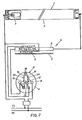
- FIG. 2 A design of the ignition device according to FIG. 1 will now be described with reference to FIG. 2.
- the same reference numerals are used for corresponding elements.
- coiled electrodes are used, as is shown with reference to the electrode 3.
- the start winding 9 superimposed on the current-limiting winding 6 has a zigzag shape; this gives a high absolute resistance.
- the start winding 9 can consist of thin wire or stamped thin sheet metal.
- the main switch 8 and the switching element 10 are combined in this embodiment to form a switching unit 11 of mechanical design.
- the main switch 8 has a Z-shaped contact knife (wiping contact) 12 which can be rotated from the switch-off to the switch-on position by means of a rotatable actuating member 13.
- the contact knife 12 interacts with two contacts 14, 15 (FIGS. 3 and 4), of which one contact 14 is connected to the phase conductor Ph.
- one end of the current limiting winding 6 and a contact spring 16 are connected, which together with a contact spring 17, which is connected to one end of the starting winding 9, forms the switching element 10.
- Both contact springs 16, 17 are provided with contacts 18 and rest on fixed supports 34.
- An actuating shaft of rectangular or square cross section connected to the actuating member 13 runs between the two contact springs 16, 17.
- the switching element 10 is of electronic design.
- the switching element 10 is not arranged as an ignition pulse generator between the phase conductor Ph and the start winding 9. 5
- the two ends of the coiled electrodes 3, 4 are connected to one another.
- a two-way rectifier 20 is connected in a bridge circuit between one end of the start winding 9 and the connection 0.
- a thyristor 21 is connected to the rectifier bridge 20.
- the positive connection of the rectifier 20 and the anode A of the thyristor 21 are connected to a capacitor 24 via a diode 22 and a resistor 23.
- a resistor 25 is connected in parallel with this capacitor 24.
- the control electrode (gate) G of the thyristor 21 is connected to the capacitor 24 via a zener diode 26.
- Two resistors 27 and 28 are connected to the cathode K and the negative connection of the rectifier 21, each of which is connected to one of the electrode connections of the Zener diode 26.
- the operation of the ignition device according to FIG. 5 corresponds to the operation explained on the basis of the circuit diagram according to FIG. 1.
- the switching element 10 works as follows:
- the capacitor 24 Before the main switch 8 is closed, the capacitor 24 is discharged.
- the supply voltage U When the supply voltage U is applied by closing the main switch 8, the capacitor 24 charges up, which results in the generation of ignition pulses for the thyristor 21, which are applied to the control electrode G.
- the thyristor 21 is ignited by these ignition pulses, whereby a discharge of the capacitor 24 is initiated.
- the supply voltage U crosses zero, the thyristor 21 extinguishes again, as a result of which the discharge process at the condenser gate 24 is interrupted.
- the process described above ie the capacitor 24 charges again until the thyristor 21 is triggered again by ignition pulses.
- This alternating firing and extinguishing of the thyristor 21 and the charging and discharging of the capacitor 24 takes place until the voltage across the capacitor 24 has reached a certain value.
- the size of this value depends on the one hand on the characteristic (Zener voltage) of the Zener diode 26 and on the other hand on the size of the supply voltage U.
- the time until the capacitor 24 is charged to the above-mentioned threshold value thus determines the on-time of the start winding 9. Since the size of this value, as mentioned, depends, among other things, on the size of the supply voltage U, the on-time of the start winding 9 changes with the supply voltage U. With the circuit described, however, it is ensured that the rated duration of the starter winding 9 is at most 10 periods of the supply voltage U at rated supply voltage. However, this dependence of the switch-on time of the starter winding 9 on the mains voltage U can be eliminated by a corresponding additional expenditure in terms of circuitry. In contrast to the embodiment shown in FIG. 2, in the embodiment according to FIG. 5 the switching element 10 is independent of the main switch 8 and can therefore be spatially separated from it. be classified. This allows the switching element 10 to be accommodated in the lamp fitting, preferably adjacent to the current limiting element 5. It is thus readily possible to switch a plurality of lamps 1 on and off using a main switch 8 in the manner described.
- the switching element 10 can also be of a suitable electromechanical type and can be formed, for example, by a relay circuit.
- a relay circuit also has the advantage that it can be spatially separated from the main switch 8.
- lamps 1 with coiled electrodes 3, 4 can also be safely ignited in this way.
- the preheating of the electrodes is preferably used to ignite the discharge, but there are many shortcomings here that have mostly been neglected.
- the main disadvantage lies in the great time between electrode heating and electron emission, in which the discharge lamp is ignited.
- Another disadvantage of preheating is that the corresponding circuit is arranged as a shunt, so that after switching off the shunt circuit, the two double-sided current feedthroughs necessary for heating the electrodes through the squeeze foot of the discharge vessel or when switching to stationary operation, the electrodes are only on one side be fed. The arc then takes the shortest path after ignition, i.e. H.
- the electrode designated 29 has a metal cup 30 which is provided with discharge or emission peaks 31 on its edge.
- the connections 32 are fastened to the bottom of the metal cup 30.
- a filling 33 which consists of an electron-emitting material, preferably rare earth metal oxides.
- the discharge tips 31 are curved outwards in their longitudinal direction, as is shown in FIG. 6 with the dashed lines discharge tip 31 'is shown.
- the discharge tips 31 are not directed parallel to one another, but diverge like tulips.
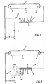
- FIGS. 7 and 8 show further embodiments of the present invention and a possibility of reducing the circuit complexity for forming the current limiting element that generates the ignition voltage.
- the circuits correspond essentially to those of FIG. 1, but here the current limiting winding 6 is provided with a tap T through which the current limiting winding 6 is divided into two winding parts 6a and 6b.
- This tap T makes it possible, in a manner to be described below, to form a converter in the economy circuit from the current limiting winding 6.
- the tap T is connected to the mains connection 0 via the switching element 10.
- the tap T can be connected to the phase conductor Ph via a switch contact 10a of a switching element 10, whereas the end of the winding part 6a via a changeover contact 10b, which also forms part of the switching element 10, either to the one mains connection 0 or to the other network connection Ph can be connected.
- an ignition voltage is generated, which results in an immediate arc discharge between the electrodes 3 and 4.
- the switching element 10 is opened again, whereby the transformer circuit of the current limiting winding 6 is canceled and this now takes over its function of stabilizing the operation of the ignited discharge lamp 1.
- FIG. 8 works in a similar manner, however, when the main switch 8 is closed, the switch contact 10a is also closed and the changeover contact 10b is brought into the position shown. As a result, the winding part 6a is connected to the two network connections 0 and Ph. A voltage is now induced in the winding part 6b and the secondary voltage generated by the economy circuit of the current limiting winding 6, which is higher than the supply voltage U, is applied as an ignition voltage to the electrodes 3 and 4. In this case, too, an ignition voltage is generated by appropriate selection of the number of turns of the winding parts 6a and 6b, which is sufficient to cause an immediate arc discharge between the electrodes 3 and 4.
- the switching element 10 is actuated again after a short time, i. H. the switch contact 10a is opened and the switch contact 10b is switched to the dashed position. As a result, the circuit of the current limiting winding 6 as an autotransformer is canceled and the current limiting winding 6 is connected in series with the discharge lamp 1.
- the embodiment according to FIG. 7 has the advantage over that of FIG. 8 that the switching element 10 can be made simpler.
- the switching elements 10 can be of mechanical, electromechanical or electronic type. 7 and 8, the switching elements 10 can be designed in accordance with FIGS. 2 and 5.
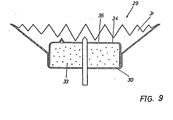
- FIG. 9 Another embodiment of the electrode is shown in FIG. 9. This electrode is even easier to manufacture and has a much longer life.
- the electrode 29 also has a metal cup 30 here, which is provided with discharge or emission tips 31 at its edge.
- a cover 34 is provided which prevents the powder material forming the filling 33 from escaping.
- small openings 36 which are aligned with the discharge path. This means that the electron current is filtered like through a sieve and the arc can emerge like a soft water jet.
- the invention allows a cold start with spiral electrodes, which has not been the case up to now.
- the inventive measures increase the service life of the electrodes extremely, the reasons being that no direct impact of ions and electrons occurs on the emission substances, since the first impact on the easily and immediately heatable emission tips of the metal cup, which is preferably made of molybdenum exists, takes place. There is also no overheating and no degradation at individual points on the helix electrodes, since the number of electrons is determined by the need and not by a preheating system which can only be adapted inaccurately. Because the front of the electrode runs transversely to the lamp axis, there is no preference given to certain points originating from production. Finally, the heat conduction of the electrodes produced according to the invention is ideal, so that the first ignition voltage surge immediately prepares the continuous operating state.
Landscapes
- Circuit Arrangements For Discharge Lamps (AREA)
Claims (11)
Priority Applications (4)
| Application Number | Priority Date | Filing Date | Title |
|---|---|---|---|
| AT81890092T ATE7982T1 (de) | 1980-05-30 | 1981-05-29 | System zur sofortzuendung und zum langlebigen betrieb von entladungslampen. |
| AU77369/81A AU541339B2 (en) | 1980-11-18 | 1981-11-11 | System for the ignition of discharge lamps |
| HU337081A HU185154B (en) | 1980-11-18 | 1981-11-11 | Arrangement for firing of discharge lamp |
| ES507173A ES507173A0 (es) | 1980-11-18 | 1981-11-16 | Perfeccionamientos en los sistemas para el encendido de lam paras de descarga. |
Applications Claiming Priority (6)
| Application Number | Priority Date | Filing Date | Title |
|---|---|---|---|
| CH4204/80 | 1980-05-30 | ||
| CH420480A CH635968A5 (en) | 1980-05-30 | 1980-05-30 | Method and circuit arrangement for immediate starting of a discharge lamp |
| DE19803043526 DE3043526A1 (de) | 1980-05-30 | 1980-11-18 | Verfahren und vorrichtung zum zuenden von niederdruck-entladungslampen, vorzugsweise leuchtstofflampen |
| DE3043526 | 1980-11-18 | ||
| DE19803045971 DE3045971A1 (de) | 1980-12-05 | 1980-12-05 | Verfahren und vorrichtung zum zuenden von niederdruck-entladungslampen, vorzugsweise leuchtstofflampen |
| DE3045971 | 1980-12-05 |
Publications (2)
| Publication Number | Publication Date |
|---|---|
| EP0041499A1 EP0041499A1 (fr) | 1981-12-09 |
| EP0041499B1 true EP0041499B1 (fr) | 1984-06-13 |
Family
ID=27174755
Family Applications (1)
| Application Number | Title | Priority Date | Filing Date |
|---|---|---|---|
| EP19810890092 Expired EP0041499B1 (fr) | 1980-05-30 | 1981-05-29 | Système pour l'allumage instantané et le fonctionnement de longue durée de lampes à décharge |
Country Status (1)
| Country | Link |
|---|---|
| EP (1) | EP0041499B1 (fr) |
Families Citing this family (2)
| Publication number | Priority date | Publication date | Assignee | Title |
|---|---|---|---|---|
| JPS59500030A (ja) * | 1982-01-15 | 1984-01-05 | ブ−ザ−.ヨハン | 不眩性螢光灯光の形成 |
| CH642775A5 (de) * | 1982-05-13 | 1984-04-30 | Johann Buser | Entladungsgefaess mit hochstromdurchfuehrungen. |
Family Cites Families (9)
| Publication number | Priority date | Publication date | Assignee | Title |
|---|---|---|---|---|
| CH144136A (fr) * | 1928-10-06 | 1930-12-15 | Capello Lamberto | Tube luminescent. |
| AT183479B (de) * | 1953-03-07 | 1955-10-10 | Joseph Carl Dr Pole | Elektrode für Entladungsröhren |
| CH468140A (de) * | 1968-04-04 | 1969-01-31 | Knobel Dubs Fritz | Starterlose Schaltungsanordnung für den Betrieb einer oder mehrerer Niederspannungs-Fluoreszenzlampen |
| DE2060473A1 (de) * | 1970-12-09 | 1972-06-15 | Bbc Brown Boveri & Cie | Schaltungsanordnung zum Zuenden und zum Betrieb von elektrischen Entladungslampen,insbesondere Dampfentladungslampen |
| DE2060474C3 (de) * | 1970-12-09 | 1974-11-28 | Brown, Boveri & Cie Ag, 6800 Mannheim | Zündgerät für eine mit Vorschaltgerät betriebene Entladungslampe |
| US3699385A (en) * | 1970-12-30 | 1972-10-17 | Sylvania Electric Prod | Control circuit for starting, sustaining and operating arc lamps |
| CH561498A5 (fr) * | 1973-02-16 | 1975-04-30 | Leuenberger H | |
| HU173720B (hu) * | 1976-04-08 | 1979-07-28 | Egyesuelt Izzolampa | Ehlektroskhema dlja ehskpluatacii gazorazrjadnoj lampi |
| US4184103A (en) * | 1978-05-04 | 1980-01-15 | Universal Manufacturing Corporation | Gas discharge lamp ballast with equally spaced windings |
-
1981
- 1981-05-29 EP EP19810890092 patent/EP0041499B1/fr not_active Expired
Also Published As
| Publication number | Publication date |
|---|---|
| EP0041499A1 (fr) | 1981-12-09 |
Similar Documents
| Publication | Publication Date | Title |
|---|---|---|
| DE2552981C3 (de) | Schaltungsanordnung zum Zünden und zum Betrieb wenigstens einer Gas- und/oder Dampfentladungslampe | |
| DE2925691C2 (de) | Schaltungsanordnung zum Zünden und Speisen mindestens einer Gas- und/oder Dampfentladungslampe | |
| DE2913525A1 (de) | Vorschaltgeraet fuer aus dem wechselstromnetz gespeiste gasentladungslampen | |
| DE69322931T2 (de) | Vorschaltgerät für eine Hochleistungsentladungslampe | |
| DE2948539A1 (de) | Leuchtstoffleuchte | |
| DE3021209A1 (de) | Beleuchtungseinheit | |
| EP0111373B1 (fr) | Dispositif de circuit pour mise en marche et fonctionnement de lampes de décharge à gaz et à haute pression | |
| EP0178735B1 (fr) | Dispositif de circuit pour enflammer et mettre en marche des lampes à décharge au gaz | |
| EP2025208A1 (fr) | Lampe à décharge à haute pression avec aptitude à l'allumage améliorée et générateur d'impulsions à haute tension | |
| EP0041499A1 (fr) | Système pour l'allumage instantané et le fonctionnement de longue durée de lampes à décharge | |
| DE3536385C2 (fr) | ||
| DE3106201A1 (de) | Hochdruck-gasentladungslampe | |
| DE961123C (de) | Elektrische Hochdruckentladungslampe | |
| DE3043526A1 (de) | Verfahren und vorrichtung zum zuenden von niederdruck-entladungslampen, vorzugsweise leuchtstofflampen | |
| DE1809455A1 (de) | Schaltungsanordnung zum Steuern der Helligkeit einer Gasentladungslampe | |
| DE3149311A1 (de) | "gasentladungslampeneinheit mit mehreren helligkeiten" | |
| DE478736C (de) | Entladungsroehre mit eingeschlossener Bogenentladung zwischen feststehenden Elektroden in einer Edelgasfuellung | |
| DE966001C (de) | Dampf- oder/und gasgefuellte Entladungslampe, insbesondere Leuchtstoffroehre | |
| DE552060C (de) | Einrichtung zum Zuenden von elektrischen Leuchtroehren | |
| DE1128920B (de) | Zuendschaltung fuer Hochdruck-Gasentladungslampen | |
| AT206990B (de) | Zünd- und Betriebseinrichtung für elektrische Entladungsröhren | |
| AT100113B (de) | Entladungsröhre. | |
| DE1589229A1 (de) | Zuendschaltung fuer eine Gasentladungslampe | |
| DE679073C (de) | Einrichtung zum Abschalten eines elektrischen Stromkreises bei Unter- oder UEberschreiten von Sollwerten der Stromstaerke | |
| DE1199399B (de) | Schaltungsanordnung zum starterlosen Zuenden von Gasentladungslampen |
Legal Events
| Date | Code | Title | Description |
|---|---|---|---|
| PUAI | Public reference made under article 153(3) epc to a published international application that has entered the european phase |
Free format text: ORIGINAL CODE: 0009012 |
|
| AK | Designated contracting states |
Designated state(s): AT CH FR GB IT LI NL SE |
|
| 17P | Request for examination filed |
Effective date: 19811027 |
|
| GRAA | (expected) grant |
Free format text: ORIGINAL CODE: 0009210 |
|
| AK | Designated contracting states |
Designated state(s): AT CH FR GB IT LI NL SE |
|
| PG25 | Lapsed in a contracting state [announced via postgrant information from national office to epo] |
Ref country code: SE Effective date: 19840613 Ref country code: NL Effective date: 19840613 Ref country code: IT Free format text: LAPSE BECAUSE OF FAILURE TO SUBMIT A TRANSLATION OF THE DESCRIPTION OR TO PAY THE FEE WITHIN THE PRESCRIBED TIME-LIMIT;WARNING: LAPSES OF ITALIAN PATENTS WITH EFFECTIVE DATE BEFORE 2007 MAY HAVE OCCURRED AT ANY TIME BEFORE 2007. THE CORRECT EFFECTIVE DATE MAY BE DIFFERENT FROM THE ONE RECORDED. Effective date: 19840613 |
|
| REF | Corresponds to: |
Ref document number: 7982 Country of ref document: AT Date of ref document: 19840615 Kind code of ref document: T |
|
| ET | Fr: translation filed | ||
| NLV1 | Nl: lapsed or annulled due to failure to fulfill the requirements of art. 29p and 29m of the patents act | ||
| PLBE | No opposition filed within time limit |
Free format text: ORIGINAL CODE: 0009261 |
|
| STAA | Information on the status of an ep patent application or granted ep patent |
Free format text: STATUS: NO OPPOSITION FILED WITHIN TIME LIMIT |
|
| PGFP | Annual fee paid to national office [announced via postgrant information from national office to epo] |
Ref country code: AT Payment date: 19850530 Year of fee payment: 5 |
|
| 26N | No opposition filed | ||
| PG25 | Lapsed in a contracting state [announced via postgrant information from national office to epo] |
Ref country code: AT Effective date: 19860529 |
|
| PG25 | Lapsed in a contracting state [announced via postgrant information from national office to epo] |
Ref country code: LI Effective date: 19860531 Ref country code: CH Effective date: 19860531 |
|
| GBPC | Gb: european patent ceased through non-payment of renewal fee | ||
| REG | Reference to a national code |
Ref country code: CH Ref legal event code: PL |
|
| PG25 | Lapsed in a contracting state [announced via postgrant information from national office to epo] |
Ref country code: FR Free format text: LAPSE BECAUSE OF NON-PAYMENT OF DUE FEES Effective date: 19880129 |
|
| REG | Reference to a national code |
Ref country code: FR Ref legal event code: ST |
|
| PG25 | Lapsed in a contracting state [announced via postgrant information from national office to epo] |
Ref country code: GB Effective date: 19881118 |