EP0042020A1 - Konvergenzeinheit für Kathodenstrahlröhre - Google Patents
Konvergenzeinheit für Kathodenstrahlröhre Download PDFInfo
- Publication number
- EP0042020A1 EP0042020A1 EP80301992A EP80301992A EP0042020A1 EP 0042020 A1 EP0042020 A1 EP 0042020A1 EP 80301992 A EP80301992 A EP 80301992A EP 80301992 A EP80301992 A EP 80301992A EP 0042020 A1 EP0042020 A1 EP 0042020A1
- Authority
- EP
- European Patent Office
- Prior art keywords
- pole
- windings
- magnetic fields
- turns
- convergence unit
- Prior art date
- Legal status (The legal status is an assumption and is not a legal conclusion. Google has not performed a legal analysis and makes no representation as to the accuracy of the status listed.)
- Granted
Links
- 238000004804 winding Methods 0.000 claims abstract description 29
- 238000010894 electron beam technology Methods 0.000 description 1
- 238000000465 moulding Methods 0.000 description 1
- 229910000595 mu-metal Inorganic materials 0.000 description 1
- 230000035945 sensitivity Effects 0.000 description 1
- 230000003068 static effect Effects 0.000 description 1
- 229910000859 α-Fe Inorganic materials 0.000 description 1
Images

Classifications
-
- H—ELECTRICITY
- H01—ELECTRIC ELEMENTS
- H01J—ELECTRIC DISCHARGE TUBES OR DISCHARGE LAMPS
- H01J29/00—Details of cathode-ray tubes or of electron-beam tubes of the types covered by group H01J31/00
- H01J29/46—Arrangements of electrodes and associated parts for generating or controlling the ray or beam, e.g. electron-optical arrangement
- H01J29/70—Arrangements for deflecting ray or beam
- H01J29/701—Systems for correcting deviation or convergence of a plurality of beams by means of magnetic fields at least
- H01J29/702—Convergence correction arrangements therefor
-
- H—ELECTRICITY
- H01—ELECTRIC ELEMENTS
- H01J—ELECTRIC DISCHARGE TUBES OR DISCHARGE LAMPS
- H01J2229/00—Details of cathode ray tubes or electron beam tubes
- H01J2229/56—Correction of beam optics
- H01J2229/568—Correction of beam optics using supplementary correction devices
- H01J2229/5681—Correction of beam optics using supplementary correction devices magnetic
- H01J2229/5687—Auxiliary coils
Definitions
- This invention relates to a convergence unit for an in-line gun shadow mask cathode-ray tube.
- a quadrupole magnetic field influences the beams generated by the three in-line guns by moving the outer beams in opposite directions and that a six-pole magnetic field moves the outer beams in the same direction.
- British Patent Specification 1466732 describes the use of quadrupole and six-pole fields in converging in-line beams.
- the quadrupole unit consists of two concentric magnetic rings each with four poles distributed about its periphery.
- the two rings are relatively rotatable and can also be rotated together as a unit.
- the strength of the quadrupole field is adjusted by adjusting the relative angular position of the two rings.
- the direction of the quadrupole field is determined by the angular position of the unit.
- a similar arrangement is provided for adjusting the six-pole field.
- British Patent Specification 1532462 describes how, for more accurate convergence, the six-pole two concentric magnetic ring arrangement should be replaced by two such arrangements each mounted asymmetrically of the in-line beams.
- the specification also describes how each six-pole structure can be replaced by a twelve-pole electromagnet connected as two six-pole electromagnets angularly separated by 30°.
- the disadvantage of this proposal is that very careful adjustment is required not to lead to shift of the centre beam. This excludes use as a dynamic convergence unit.
- a convergence unit for use with an in-line gun shadow mask cathode-ray tube comprises means for generating six-pole and four-pole magnetic fields centred on the central axis of the tube neck, wherein the means for generating the six-pole magnetic fields includes a pair of six-pole windings on a common core and arranged when energised to generate respective six-pole magnetic fields differing in angular position by 30°, characterised in that the means for generating the four-pole magnetic fields includes a pair of four-pole windings on a common core and arranged when energised to generate respective four-pole magnetic fields differing in angular position by 45°, and in that the six-pole and four-pole windings are on the same common toroidal core.
- the unit according to the invention is preferably a dynamic convergence unit but its use as a static convergence unit is possible.
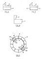
- a mu-metal or ferrite toroid 10 has one annular face divided into twelve equal segments by non-magnetic ribs 11 (see also Figure 2).
- Each rib is provided with a projection 12 which extends so as to form a peg or hook about which the wire of the winding can be secured, as will be explained below.
- Figure 3 shows an alternative design.
- the projections 12 are studs and the ribs 11 extend outwardly from a circular band 13 of such size as to fit closely within the inner circumference of toroid 10.
- the design of Figure 3 has the advantage that the ribs 11 do not need to be secured to the toroid 10, as is necessary with the design of Figure 2.
- Another design of projection 12, which makes moulding of the ribs easier, is shown in Figure 4.
- Figure 1 shows schematically the locations and connections of the four windings.
- all turns are wound in the same direction and, since it is required to have current flowing in opposite directions in successive sets of turns in order to minimise the inductance, alternate sets of turns are wound in one operation and connections are made after the winding operation.
- the twelve ribs 11 are referenced according to their positions on the toroid 10, in the manner of the hours of a clockface, using roman numerals.
- each winding is shown separately on toroid 10.
- the first four-pole winding has sets of turns 14A to 14D. Turns 14A are between ribs XI and I and are continued as turns 14B between ribs V and VII.
- the windings 14A, 14B terminate at A1.
- Turns 14C are between ribs VIII and X and are continued as turns 14D between ribs II and IV.
- the end Bl of turns 14D is connected to end Al of turns 14B.
- Drive currents are supplied to ends A and B of turns 14A and 14C, respectively.
- the second four-pole winding winding comprises turns 15A to 15D between ribs X and XI, IV and V, VII and VIII, and I and II, respectively.
- the windings 15A, 15B and 15C, 15D are, respectively, continuous.
- the ends C1 and D1 of turns 15B and 15C are connected and power is supplied to ends C and D of turns 15A and 15D.
- the first six-pole winding comprises sets of turns 16A to 16F of which windings 16A to 16C and 16D to 16F are, respectively, continuous.
- the sets of turns 16A to 16F are respectively between ribs XII and I, IV and V, VIII and IX, X and XI, II and III and VI and VII.
- the end El of turns 16C is connected to the end Fl of turns 16F. Power is supplied to the ends E and F of turns 16A and 16D, respectively.
- the second six-pole winding occupies the segments of toroid 10 not occupied by the first six-pole winding and comprises the six sets of turns 17A to 17F, of which 17A to 17C and 17D to 17F are, respectively, continuous, and of which the end Gl of turns 17C is connected to the end H1 of turns 17F. Power is supplied to the ends G and H of turns 17A and 17D.
- Figure 5 shows the use of the projections 12.
- sets of turns 15A and 15B are shown.
- the wire is taken about projection 18 of rib 10, the desired number of turns is made and the wire taken about projection 19 of rib XI.
- the wire is then taken to projection 20 of rib IV, engaging the projections 12 of the intervening ribs.
- the turns 15B are then made and the wire taken about projections 21 of rib V, leaving the end C1 free.
- the stored value appropriate to the current position of the beams is retrieved, converted to its analogue current equivalent and supplied to the convergence unit. Since there are four windings on the convergence unit, there will, in fact, be four digital values corresponding to any given position of the beams.
Landscapes
- Video Image Reproduction Devices For Color Tv Systems (AREA)
- Coils Of Transformers For General Uses (AREA)
Priority Applications (4)
| Application Number | Priority Date | Filing Date | Title |
|---|---|---|---|
| EP80301992A EP0042020B1 (de) | 1980-06-13 | 1980-06-13 | Konvergenzeinheit für Kathodenstrahlröhre |
| DE8080301992T DE3067822D1 (en) | 1980-06-13 | 1980-06-13 | Convergence unit for cathode-ray tube |
| JP5638781A JPS5715346A (en) | 1980-06-13 | 1981-04-16 | Braun tube converging unit |
| US06/271,739 US4339736A (en) | 1980-06-13 | 1981-06-08 | Convergence unit for cathode-ray tube |
Applications Claiming Priority (1)
| Application Number | Priority Date | Filing Date | Title |
|---|---|---|---|
| EP80301992A EP0042020B1 (de) | 1980-06-13 | 1980-06-13 | Konvergenzeinheit für Kathodenstrahlröhre |
Publications (2)
| Publication Number | Publication Date |
|---|---|
| EP0042020A1 true EP0042020A1 (de) | 1981-12-23 |
| EP0042020B1 EP0042020B1 (de) | 1984-05-16 |
Family
ID=8187188
Family Applications (1)
| Application Number | Title | Priority Date | Filing Date |
|---|---|---|---|
| EP80301992A Expired EP0042020B1 (de) | 1980-06-13 | 1980-06-13 | Konvergenzeinheit für Kathodenstrahlröhre |
Country Status (4)
| Country | Link |
|---|---|
| US (1) | US4339736A (de) |
| EP (1) | EP0042020B1 (de) |
| JP (1) | JPS5715346A (de) |
| DE (1) | DE3067822D1 (de) |
Cited By (1)
| Publication number | Priority date | Publication date | Assignee | Title |
|---|---|---|---|---|
| DE3235614A1 (de) * | 1981-09-25 | 1983-04-14 | Denki Onkyo Co., Ltd., Tokyo | Konvergenzeinrichtung fuer farbkathodenstrahlroehren |
Families Citing this family (4)
| Publication number | Priority date | Publication date | Assignee | Title |
|---|---|---|---|---|
| JPS58184978U (ja) * | 1982-05-31 | 1983-12-08 | 株式会社村田製作所 | カラ−陰極線管用コンバ−ジエンス装置 |
| US4405910A (en) * | 1981-09-25 | 1983-09-20 | Denki Onkyo Company Limited | Convergence apparatus for color cathode-ray tube |
| JPS58218290A (ja) * | 1982-06-11 | 1983-12-19 | Denki Onkyo Co Ltd | インライン型カラ−陰極線管用コンバ−ジエンス装置 |
| DE19707069A1 (de) * | 1997-02-22 | 1998-08-27 | Thomson Brandt Gmbh | Vorrichtung zur Elektronenstrahlablenkung in einer Kathodenstrahlröhre |
Citations (9)
| Publication number | Priority date | Publication date | Assignee | Title |
|---|---|---|---|---|
| DE2318465A1 (de) * | 1972-04-13 | 1973-10-18 | Gen Electric | Ablenk- und konvergenzanordnung fuer eine farbkatodenstrahlroehre mit in einer linie nebeneinanderliegenden elektronenstrahlen |
| US3806757A (en) * | 1971-06-23 | 1974-04-23 | Denki Onkyo Co Ltd | In-line gun type color television picture tube apparatus |
| DE2459477A1 (de) * | 1974-02-08 | 1975-08-14 | Videon Sa | Vorrichtung zur verbesserung der konvergenz von zeilen oben und unten am bildschirm einer farbkatodenstrahlroehre mit in-line-kanonen |
| DE2549054A1 (de) * | 1974-11-14 | 1976-05-26 | Philips Nv | Anordnung zum wiedergeben von farbfernsehbildern |
| GB1466732A (en) * | 1973-04-09 | 1977-03-09 | Philips Electronic Associated | Magnetic corerection device for a cathode ray tube |
| GB1467475A (en) * | 1973-07-13 | 1977-03-16 | Videon Sa | Device for the deflection and convergence correction of electron beams |
| GB1517119A (en) * | 1976-12-22 | 1978-07-12 | Ibm | Cathode ray tube control apparatus |
| GB1532462A (en) * | 1975-03-13 | 1978-11-15 | Philips Electronic Associated | Static convergence unit |
| DE2827458A1 (de) * | 1977-06-23 | 1979-01-25 | Matsushita Electric Ind Co Ltd | Konvergenzvorrichtung fuer projektions- farbfernsehsystem |
Family Cites Families (3)
| Publication number | Priority date | Publication date | Assignee | Title |
|---|---|---|---|---|
| IT1050924B (it) * | 1975-11-21 | 1981-03-20 | Indesit | Dispositivo per la regolazione dei fasci elettronici di un cinescopio |
| US4128824A (en) * | 1977-09-29 | 1978-12-05 | Rca Corporation | Multilayered deflection yoke |
| US4228413A (en) * | 1978-12-11 | 1980-10-14 | Rca Corporation | Saddle-toroid deflection winding for low loss and/or reduced conductor length |
-
1980
- 1980-06-13 EP EP80301992A patent/EP0042020B1/de not_active Expired
- 1980-06-13 DE DE8080301992T patent/DE3067822D1/de not_active Expired
-
1981
- 1981-04-16 JP JP5638781A patent/JPS5715346A/ja active Granted
- 1981-06-08 US US06/271,739 patent/US4339736A/en not_active Expired - Fee Related
Patent Citations (9)
| Publication number | Priority date | Publication date | Assignee | Title |
|---|---|---|---|---|
| US3806757A (en) * | 1971-06-23 | 1974-04-23 | Denki Onkyo Co Ltd | In-line gun type color television picture tube apparatus |
| DE2318465A1 (de) * | 1972-04-13 | 1973-10-18 | Gen Electric | Ablenk- und konvergenzanordnung fuer eine farbkatodenstrahlroehre mit in einer linie nebeneinanderliegenden elektronenstrahlen |
| GB1466732A (en) * | 1973-04-09 | 1977-03-09 | Philips Electronic Associated | Magnetic corerection device for a cathode ray tube |
| GB1467475A (en) * | 1973-07-13 | 1977-03-16 | Videon Sa | Device for the deflection and convergence correction of electron beams |
| DE2459477A1 (de) * | 1974-02-08 | 1975-08-14 | Videon Sa | Vorrichtung zur verbesserung der konvergenz von zeilen oben und unten am bildschirm einer farbkatodenstrahlroehre mit in-line-kanonen |
| DE2549054A1 (de) * | 1974-11-14 | 1976-05-26 | Philips Nv | Anordnung zum wiedergeben von farbfernsehbildern |
| GB1532462A (en) * | 1975-03-13 | 1978-11-15 | Philips Electronic Associated | Static convergence unit |
| GB1517119A (en) * | 1976-12-22 | 1978-07-12 | Ibm | Cathode ray tube control apparatus |
| DE2827458A1 (de) * | 1977-06-23 | 1979-01-25 | Matsushita Electric Ind Co Ltd | Konvergenzvorrichtung fuer projektions- farbfernsehsystem |
Cited By (1)
| Publication number | Priority date | Publication date | Assignee | Title |
|---|---|---|---|---|
| DE3235614A1 (de) * | 1981-09-25 | 1983-04-14 | Denki Onkyo Co., Ltd., Tokyo | Konvergenzeinrichtung fuer farbkathodenstrahlroehren |
Also Published As
| Publication number | Publication date |
|---|---|
| JPH0151851B2 (de) | 1989-11-07 |
| EP0042020B1 (de) | 1984-05-16 |
| DE3067822D1 (en) | 1984-06-20 |
| JPS5715346A (en) | 1982-01-26 |
| US4339736A (en) | 1982-07-13 |
Similar Documents
| Publication | Publication Date | Title |
|---|---|---|
| US4027219A (en) | Device for displaying color television images | |
| US4354218A (en) | Process and apparatus for multi-polar magnetization of annular permanent magnets | |
| US3895329A (en) | Toroidal-like saddle yoke | |
| FI70758C (fi) | Anordning foer instaellning av statisk konvergens hos ett katodstraolroer | |
| PL109121B1 (en) | Apparatus for reproducing pictures | |
| US4227122A (en) | Convergence device for projection type color television system | |
| US4339736A (en) | Convergence unit for cathode-ray tube | |
| GB1226614A (de) | ||
| US4189659A (en) | Color-television picture tube with internal permanent magnets for convergence correction | |
| US3375389A (en) | Adjustable convergence magnets | |
| US5115170A (en) | Deflection yoke for use in color cathode ray tubes | |
| US4833432A (en) | Saturable reactor for use in self-convergence system fo deflection yoke | |
| US3548350A (en) | Wide angle deflection yoke for producing optimally non-uniform deflection fields | |
| US3808568A (en) | Stator yoke | |
| US4470029A (en) | Convergence unit for in-line color cathode ray tube | |
| US3098942A (en) | Magnetic centering device for cathode ray tubes | |
| US2881341A (en) | Deflection yoke | |
| GB2037068A (en) | Deflection yoke assembly including a beam positioning magnet arrangement | |
| US4538127A (en) | Magnetic quadripole | |
| US3811066A (en) | Television camera comprising an interference-free mesh connection conductor | |
| US4152684A (en) | Device for the magnetic deflection of electron beams | |
| EP0090108B1 (de) | Konvergenzeinheit für Farbkathodenstrahlröhre | |
| JPH051893Y2 (de) | ||
| JPS642242A (en) | Deflection yoke | |
| US4122421A (en) | Device for the control of electron beams of a cathode ray tube |
Legal Events
| Date | Code | Title | Description |
|---|---|---|---|
| PUAI | Public reference made under article 153(3) epc to a published international application that has entered the european phase |
Free format text: ORIGINAL CODE: 0009012 |
|
| AK | Designated contracting states |
Designated state(s): DE FR GB IT |
|
| 17P | Request for examination filed |
Effective date: 19820119 |
|
| ITF | It: translation for a ep patent filed | ||
| GRAA | (expected) grant |
Free format text: ORIGINAL CODE: 0009210 |
|
| AK | Designated contracting states |
Designated state(s): DE FR GB IT |
|
| PGFP | Annual fee paid to national office [announced via postgrant information from national office to epo] |
Ref country code: FR Payment date: 19840605 Year of fee payment: 5 |
|
| PGFP | Annual fee paid to national office [announced via postgrant information from national office to epo] |
Ref country code: DE Payment date: 19840619 Year of fee payment: 5 |
|
| REF | Corresponds to: |
Ref document number: 3067822 Country of ref document: DE Date of ref document: 19840620 |
|
| ET | Fr: translation filed | ||
| PLBE | No opposition filed within time limit |
Free format text: ORIGINAL CODE: 0009261 |
|
| STAA | Information on the status of an ep patent application or granted ep patent |
Free format text: STATUS: NO OPPOSITION FILED WITHIN TIME LIMIT |
|
| 26N | No opposition filed | ||
| PGFP | Annual fee paid to national office [announced via postgrant information from national office to epo] |
Ref country code: GB Payment date: 19890531 Year of fee payment: 10 |
|
| PG25 | Lapsed in a contracting state [announced via postgrant information from national office to epo] |
Ref country code: FR Free format text: LAPSE BECAUSE OF NON-PAYMENT OF DUE FEES Effective date: 19900228 |
|
| PG25 | Lapsed in a contracting state [announced via postgrant information from national office to epo] |
Ref country code: DE Effective date: 19900301 |
|
| REG | Reference to a national code |
Ref country code: FR Ref legal event code: ST |
|
| PG25 | Lapsed in a contracting state [announced via postgrant information from national office to epo] |
Ref country code: GB Effective date: 19900613 |
|
| GBPC | Gb: european patent ceased through non-payment of renewal fee |