EP0042087B1 - Robinet de frein à deux circuits - Google Patents
Robinet de frein à deux circuits Download PDFInfo
- Publication number
- EP0042087B1 EP0042087B1 EP81104069A EP81104069A EP0042087B1 EP 0042087 B1 EP0042087 B1 EP 0042087B1 EP 81104069 A EP81104069 A EP 81104069A EP 81104069 A EP81104069 A EP 81104069A EP 0042087 B1 EP0042087 B1 EP 0042087B1
- Authority
- EP
- European Patent Office
- Prior art keywords
- circuit
- valve
- brake valve
- rod
- dual
- Prior art date
- Legal status (The legal status is an assumption and is not a legal conclusion. Google has not performed a legal analysis and makes no representation as to the accuracy of the status listed.)
- Expired
Links
- 238000005303 weighing Methods 0.000 description 6
- 238000009423 ventilation Methods 0.000 description 2
- 230000000694 effects Effects 0.000 description 1
- 238000011144 upstream manufacturing Methods 0.000 description 1
Images
Classifications
-
- B—PERFORMING OPERATIONS; TRANSPORTING
- B60—VEHICLES IN GENERAL
- B60T—VEHICLE BRAKE CONTROL SYSTEMS OR PARTS THEREOF; BRAKE CONTROL SYSTEMS OR PARTS THEREOF, IN GENERAL; ARRANGEMENT OF BRAKING ELEMENTS ON VEHICLES IN GENERAL; PORTABLE DEVICES FOR PREVENTING UNWANTED MOVEMENT OF VEHICLES; VEHICLE MODIFICATIONS TO FACILITATE COOLING OF BRAKES
- B60T15/00—Construction arrangement, or operation of valves incorporated in power brake systems and not covered by groups B60T11/00 or B60T13/00
- B60T15/02—Application and release valves
- B60T15/04—Driver's valves
- B60T15/043—Driver's valves controlling service pressure brakes
- B60T15/045—Driver's valves controlling service pressure brakes in multiple circuit systems, e.g. dual circuit systems
- B60T15/046—Driver's valves controlling service pressure brakes in multiple circuit systems, e.g. dual circuit systems with valves mounted in tandem
Definitions
- the invention relates to a two-circuit brake valve according to the preamble of claim 1.
- a two-circuit brake valve of the type in question is e.g. known from US-A-3 923 346. It is used in particular as a foot brake valve for the brake systems of motor vehicles, in which the brake circuits are arranged one behind the other, i.e. it is designed in tandem.
- the downstream, pneumatically controlled circuit races behind the upstream circuit in terms of pressure, for example by an amount of approximately 0.3-0.5 bar.
- the object of the invention is to form a two-circuit brake valve of the type in question in such a way that the actuating device connecting the actuating piston or stepping piston of the first circuit to the actuating piston of the second circuit is as simple as possible and enables so-called lagging of the second circle to decrease or even to cancel.
- the actuating device connecting the actuating piston or stepping piston of the first circuit to the actuating piston of the second circuit is as simple as possible and enables so-called lagging of the second circle to decrease or even to cancel.
- the device should also be designed to be space-saving and fully integrated into the valve without the brake valve having to be changed significantly subsequently; It should therefore be possible to retrofit existing systems.
- the modulated pressure of the first circuit also acts on the actuating piston of the second circuit via a connection.
- This acts as a so-called weighing piston and, according to the invention, is additionally acted upon by the rod of the actuating device, which is intercepted by a prestressed spring, with simultaneous pneumatic actuation; it is therefore applied with structurally simple means an additional force which favors the modulation of the second circuit in such a way that pressure differences between the first and second circuits are reduced or eliminated.
- the spring plate receiving the rod has corresponding adjusting means, such as a threaded hole into which the rod is screwed.
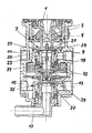
- the drawing shows a dual-circuit brake valve according to the invention as a foot brake valve for brake systems of motor vehicles.
- a double-acting brake valve which e.g. is provided as a foot brake valve.
- a brake pedal (not shown) acts on a pressure piece 1.
- the pressure piece 1 is supported by a spring arrangement 3 on a graduated piston 5, the actuating piston of the first circle.
- the stepping piston 5 acts in a known manner with respect to an inlet and outlet valve 7 of the first circuit when the movement is directed downward.
- the supply of the first circuit is present via a connection 9, while the connection 11 is connected to the brake cylinders of the first circuit.
- Corresponding connections 13 and 15 are provided in a known manner for the second circuit of the brake system.
- the outlet 17 provided on the foot brake valve is connected to a ventilation channel 19 passing through the entire brake valve in order to be able to vent (shown in the drawing) the brake systems of the first and second circuits connected to the connections 11 and 15.
- the extension 21 provided at the lower end of the stepped piston 5, which acts in a known manner to vent the brake system of the first circuit in relation to a valve element 25 attached to a valve sleeve 23 in order to release the valve element from a projection 27 fixed to the housing, is shown in FIG Embodiment according to the invention provided with a threaded screw 29, preferably screwed in from above, the relative position of which can be changed as desired. Below the threaded pin 29 there extends a rod 31, preferably at a distance from the threaded pin, which passes through the hollow ventilation channel 19 of the first circle and the second circle. The rod 31 is intercepted at its lower end as shown by the switching piston of the second circuit.
- This switching piston is in the form of a weighing piston 33 known per se, which in acts in a manner comparable to the graduated piston 5 of the first circuit with respect to an inlet and outlet valve 35.
- the rod 31 is supported on a spring plate 37, which is supported by a prestressed spring 39 with respect to a stop formed on the inside of the weighing piston. It is also possible for the rod 31 to engage a thread on the bottom of the spring plate 37.
- the threaded pin 29 acts on the upper side of the rod 31 after a predetermined distance, which in turn exerts a downward force on the weighing piston 33 via the spring plate 37.
- the stepping piston 5 acts as the actuating piston of the first circuit via the threaded pin 29, the rod 31, the spring plate 37 and the spring 39 on the weighing piston 33 as the actuating piston of the second circuit, in a precisely defined manner so that the applied pressure below the weighing piston 33 increases according to the actuating force, ie the pressure lag is reduced or completely eliminated.
Landscapes
- Engineering & Computer Science (AREA)
- Transportation (AREA)
- Mechanical Engineering (AREA)
- Valves And Accessory Devices For Braking Systems (AREA)
Claims (3)
Applications Claiming Priority (2)
| Application Number | Priority Date | Filing Date | Title |
|---|---|---|---|
| DE3022435 | 1980-06-14 | ||
| DE19803022435 DE3022435A1 (de) | 1980-06-14 | 1980-06-14 | Zweikreis-bremsventil |
Publications (2)
| Publication Number | Publication Date |
|---|---|
| EP0042087A1 EP0042087A1 (fr) | 1981-12-23 |
| EP0042087B1 true EP0042087B1 (fr) | 1983-05-18 |
Family
ID=6104679
Family Applications (1)
| Application Number | Title | Priority Date | Filing Date |
|---|---|---|---|
| EP81104069A Expired EP0042087B1 (fr) | 1980-06-14 | 1981-05-27 | Robinet de frein à deux circuits |
Country Status (2)
| Country | Link |
|---|---|
| EP (1) | EP0042087B1 (fr) |
| DE (2) | DE3022435A1 (fr) |
Families Citing this family (13)
| Publication number | Priority date | Publication date | Assignee | Title |
|---|---|---|---|---|
| DE3231978A1 (de) * | 1982-08-27 | 1984-03-01 | Knorr-Bremse GmbH, 8000 München | Druckregelventil, insbesondere fussbremsventil fuer kraftfahrzeuge |
| DE3245961A1 (de) * | 1982-12-11 | 1984-06-14 | Robert Bosch Gmbh, 7000 Stuttgart | Bremsventil fuer zweikreis-druckluftbremsanlagen, insbesondere fuer fahrzeuge |
| DE3402499A1 (de) * | 1984-01-25 | 1985-07-25 | Knorr-Bremse GmbH, 8000 München | Zweikreis-bremsventil |
| GB8507330D0 (en) * | 1985-03-21 | 1985-05-01 | Bendix Ltd | Two circuit fluid pressure control valves |
| DE3830105A1 (de) * | 1988-09-05 | 1990-03-15 | Knorr Bremse Ag | Bremsventil fuer druckluftbremsanlagen von fahrzeugen |
| DE4140750A1 (de) * | 1991-12-11 | 1993-06-17 | Wabco Westinghouse Fahrzeug | Einrichtung mit faltenbalg |
| DE4232146A1 (de) * | 1992-09-25 | 1994-03-31 | Wabco Westinghouse Fahrzeug | Zweikreisige Bremsventileinrichtung |
| CN101857019B (zh) * | 2010-05-18 | 2011-08-10 | 河南昌通科技有限公司 | 二级点刹双腔并列式制动总阀 |
| CN101857018B (zh) * | 2010-05-18 | 2011-09-14 | 河南昌通科技有限公司 | 二级点刹制动总阀 |
| GB2577710B (en) | 2018-10-03 | 2022-12-14 | Lee Ventus Ltd | Methods and devices for driving a piezoelectric pump |
| GB2576796B (en) | 2018-12-07 | 2020-10-07 | Ttp Ventus Ltd | Improved valve |
| EP3891398B1 (fr) | 2018-12-07 | 2023-01-04 | Lee Ventus Limited | Vanne améliorée |
| GB2597942B (en) | 2020-08-10 | 2022-08-03 | Ttp Ventus Ltd | Pump for microfluidic device |
Family Cites Families (5)
| Publication number | Priority date | Publication date | Assignee | Title |
|---|---|---|---|---|
| CA968830A (en) * | 1971-04-05 | 1975-06-03 | Duane R. Smith | Brake control arrangement for skidders |
| US3923346A (en) * | 1973-05-30 | 1975-12-02 | Berg Manufacturing Co | Dual circuit brake valve |
| DE2507661A1 (de) * | 1975-02-22 | 1976-09-02 | Knorr Bremse Gmbh | Zweikreisbremsventil fuer kraftfahrzeuge |
| DE2716495C2 (de) * | 1977-04-14 | 1979-03-01 | Wabco Westinghouse Gmbh, 3000 Hannover | Druckregelventil |
| DE2817991A1 (de) * | 1978-04-25 | 1979-11-08 | Bosch Gmbh Robert | Zweikreis-steuerventil |
-
1980
- 1980-06-14 DE DE19803022435 patent/DE3022435A1/de not_active Withdrawn
-
1981
- 1981-05-27 EP EP81104069A patent/EP0042087B1/fr not_active Expired
- 1981-05-27 DE DE8181104069T patent/DE3160311D1/de not_active Expired
Also Published As
| Publication number | Publication date |
|---|---|
| EP0042087A1 (fr) | 1981-12-23 |
| DE3022435A1 (de) | 1982-01-07 |
| DE3160311D1 (en) | 1983-07-07 |
Similar Documents
| Publication | Publication Date | Title |
|---|---|---|
| DE1950040C3 (de) | Relaisventil zur Begrenzung und Steuerung des Luftdrucks in einer Federspeicher-Bremsbetätigungseinrichtung | |
| EP0042087B1 (fr) | Robinet de frein à deux circuits | |
| EP3810466B1 (fr) | Dispositif de frein de stationnement pour véhicule | |
| DE102019135886A1 (de) | Hydraulikblock für eine elektronische Bremsvorrichtung für ein Fahrzeug | |
| DE2625502A1 (de) | Bremsblockierschutzeinrichtung | |
| DE3001415C2 (fr) | ||
| DE2520144C3 (de) | Relaisventil zur Begrenzung und Steuerung des Luftdrucks in einer Federspeicher-Bremsbetätigungseinrichtung | |
| DE2938140A1 (de) | Bremshauptzylinder | |
| CH644316A5 (de) | Zweikreis-druckmittelbremsanlage mit lastabhaengiger regelung fuer kraftfahrzeuge. | |
| EP0046166A1 (fr) | Installation de frein à deux conduites réglée en fonction de la charge, pour une remorque | |
| DE2643805B2 (de) | Fahrzeugbremseinrichtung | |
| DE2716495C2 (de) | Druckregelventil | |
| DE2656414A1 (de) | Schnellbetriebsbremsvorrichtung fuer druckmittel-fahrzeugbremsanlagen | |
| DE2457793B2 (de) | Fahrzeug-druckluftbremsanlage | |
| DE2251479A1 (de) | Anhaengersteuerventil | |
| EP0114192B1 (fr) | Soupape de commande de remorque | |
| DE2810850A1 (de) | Anhaenger-bremsventil | |
| EP0058773A1 (fr) | Installation de frein à air comprimé pour véhicules routiers à suspension pneumatique ayant trois et multiples essieux | |
| DE2849762C2 (de) | Fluiddruckbetätigtes Zweikreisbremssystem für Kraftfahrzeuge | |
| DE69500130T2 (de) | Bremsflüssigkeits-Drucksteuergerät | |
| EP0659622B1 (fr) | Installation de frein à deux conduites à air comprimé | |
| DE2939907A1 (de) | Zweikreis-bremsanlage | |
| DE2452188A1 (de) | Zweileitungs-zweikreisbremsanlagen fuer kraftfahrzeuge, insbesondere fuer zugmaschinen | |
| EP0169303A2 (fr) | Valve de commande pour remorques | |
| EP0546488A2 (fr) | Dispositif de soupape pour l'optimisation de la répartition de l'usure entre les freins des véhicules utilitaires |
Legal Events
| Date | Code | Title | Description |
|---|---|---|---|
| PUAI | Public reference made under article 153(3) epc to a published international application that has entered the european phase |
Free format text: ORIGINAL CODE: 0009012 |
|
| AK | Designated contracting states |
Designated state(s): DE FR NL SE |
|
| 17P | Request for examination filed |
Effective date: 19811030 |
|
| GRAA | (expected) grant |
Free format text: ORIGINAL CODE: 0009210 |
|
| AK | Designated contracting states |
Designated state(s): DE FR NL SE |
|
| REF | Corresponds to: |
Ref document number: 3160311 Country of ref document: DE Date of ref document: 19830707 |
|
| ET | Fr: translation filed | ||
| PLBI | Opposition filed |
Free format text: ORIGINAL CODE: 0009260 |
|
| 26 | Opposition filed |
Opponent name: ROBERT BOSCH GMBH Effective date: 19830715 |
|
| PLBI | Opposition filed |
Free format text: ORIGINAL CODE: 0009260 |
|
| PLBI | Opposition filed |
Free format text: ORIGINAL CODE: 0009260 |
|
| 26 | Opposition filed |
Opponent name: WABCO WESTINGHOUSE FAHRZEUGBREMSEN GMBH Effective date: 19831021 |
|
| 26 | Opposition filed |
Opponent name: GRAUBREMSE GMBH Effective date: 19831119 |
|
| PGFP | Annual fee paid to national office [announced via postgrant information from national office to epo] |
Ref country code: FR Payment date: 19840328 Year of fee payment: 4 |
|
| PGFP | Annual fee paid to national office [announced via postgrant information from national office to epo] |
Ref country code: SE Payment date: 19840331 Year of fee payment: 4 |
|
| PGFP | Annual fee paid to national office [announced via postgrant information from national office to epo] |
Ref country code: DE Payment date: 19840517 Year of fee payment: 4 |
|
| PGFP | Annual fee paid to national office [announced via postgrant information from national office to epo] |
Ref country code: NL Payment date: 19840531 Year of fee payment: 4 |
|
| RDAG | Patent revoked |
Free format text: ORIGINAL CODE: 0009271 |
|
| STAA | Information on the status of an ep patent application or granted ep patent |
Free format text: STATUS: PATENT REVOKED |
|
| 27W | Patent revoked |
Effective date: 19850326 |
|
| NLR2 | Nl: decision of opposition | ||
| REG | Reference to a national code |
Ref country code: FR Ref legal event code: ST |
|
| EUG | Se: european patent has lapsed |
Ref document number: 81104069.0 Effective date: 19860702 |