EP0042151B1 - Lampe à vapeur de sodium à haute pression - Google Patents
Lampe à vapeur de sodium à haute pression Download PDFInfo
- Publication number
- EP0042151B1 EP0042151B1 EP81104515A EP81104515A EP0042151B1 EP 0042151 B1 EP0042151 B1 EP 0042151B1 EP 81104515 A EP81104515 A EP 81104515A EP 81104515 A EP81104515 A EP 81104515A EP 0042151 B1 EP0042151 B1 EP 0042151B1
- Authority
- EP
- European Patent Office
- Prior art keywords
- arc tube
- feed
- throughs
- pressure sodium
- sodium lamp
- Prior art date
- Legal status (The legal status is an assumption and is not a legal conclusion. Google has not performed a legal analysis and makes no representation as to the accuracy of the status listed.)
- Expired
Links
- DGAQECJNVWCQMB-PUAWFVPOSA-M Ilexoside XXIX Chemical compound C[C@@H]1CC[C@@]2(CC[C@@]3(C(=CC[C@H]4[C@]3(CC[C@@H]5[C@@]4(CC[C@@H](C5(C)C)OS(=O)(=O)[O-])C)C)[C@@H]2[C@]1(C)O)C)C(=O)O[C@H]6[C@@H]([C@H]([C@@H]([C@H](O6)CO)O)O)O.[Na+] DGAQECJNVWCQMB-PUAWFVPOSA-M 0.000 title claims description 25
- 229910052708 sodium Inorganic materials 0.000 title claims description 25
- 239000011734 sodium Substances 0.000 title claims description 25
- PNEYBMLMFCGWSK-UHFFFAOYSA-N aluminium oxide Inorganic materials [O-2].[O-2].[O-2].[Al+3].[Al+3] PNEYBMLMFCGWSK-UHFFFAOYSA-N 0.000 claims description 9
- QCWXUUIWCKQGHC-UHFFFAOYSA-N Zirconium Chemical compound [Zr] QCWXUUIWCKQGHC-UHFFFAOYSA-N 0.000 claims description 5
- 229910052758 niobium Inorganic materials 0.000 claims description 5
- 239000010955 niobium Substances 0.000 claims description 5
- GUCVJGMIXFAOAE-UHFFFAOYSA-N niobium atom Chemical compound [Nb] GUCVJGMIXFAOAE-UHFFFAOYSA-N 0.000 claims description 5
- 229910052726 zirconium Inorganic materials 0.000 claims description 5
- RTAQQCXQSZGOHL-UHFFFAOYSA-N Titanium Chemical compound [Ti] RTAQQCXQSZGOHL-UHFFFAOYSA-N 0.000 claims description 4
- 239000010936 titanium Substances 0.000 claims description 4
- 229910052719 titanium Inorganic materials 0.000 claims description 4
- ZOKXTWBITQBERF-UHFFFAOYSA-N Molybdenum Chemical compound [Mo] ZOKXTWBITQBERF-UHFFFAOYSA-N 0.000 claims description 2
- 229910052750 molybdenum Inorganic materials 0.000 claims description 2
- 239000011733 molybdenum Substances 0.000 claims description 2
- 229910052715 tantalum Inorganic materials 0.000 claims 1
- GUVRBAGPIYLISA-UHFFFAOYSA-N tantalum atom Chemical compound [Ta] GUVRBAGPIYLISA-UHFFFAOYSA-N 0.000 claims 1
- 239000004568 cement Substances 0.000 description 9
- 239000000919 ceramic Substances 0.000 description 7
- 208000028659 discharge Diseases 0.000 description 5
- 239000011888 foil Substances 0.000 description 5
- 230000000694 effects Effects 0.000 description 4
- 239000000463 material Substances 0.000 description 4
- 229910052751 metal Inorganic materials 0.000 description 4
- 239000002184 metal Substances 0.000 description 4
- 238000009413 insulation Methods 0.000 description 3
- 230000008018 melting Effects 0.000 description 3
- 238000002844 melting Methods 0.000 description 3
- 238000007789 sealing Methods 0.000 description 3
- 230000035882 stress Effects 0.000 description 3
- XEEYBQQBJWHFJM-UHFFFAOYSA-N Iron Chemical compound [Fe] XEEYBQQBJWHFJM-UHFFFAOYSA-N 0.000 description 2
- 230000004323 axial length Effects 0.000 description 2
- 239000011521 glass Substances 0.000 description 2
- 238000004519 manufacturing process Methods 0.000 description 2
- 230000013011 mating Effects 0.000 description 2
- 150000002739 metals Chemical class 0.000 description 2
- VYZAMTAEIAYCRO-UHFFFAOYSA-N Chromium Chemical compound [Cr] VYZAMTAEIAYCRO-UHFFFAOYSA-N 0.000 description 1
- 229910001069 Ti alloy Inorganic materials 0.000 description 1
- 229910045601 alloy Inorganic materials 0.000 description 1
- 239000000956 alloy Substances 0.000 description 1
- 229910052782 aluminium Inorganic materials 0.000 description 1
- XAGFODPZIPBFFR-UHFFFAOYSA-N aluminium Chemical compound [Al] XAGFODPZIPBFFR-UHFFFAOYSA-N 0.000 description 1
- 229910052804 chromium Inorganic materials 0.000 description 1
- 239000011651 chromium Substances 0.000 description 1
- 239000003086 colorant Substances 0.000 description 1
- 238000010276 construction Methods 0.000 description 1
- 238000005336 cracking Methods 0.000 description 1
- 230000001419 dependent effect Effects 0.000 description 1
- 230000018109 developmental process Effects 0.000 description 1
- 238000003384 imaging method Methods 0.000 description 1
- 229910052742 iron Inorganic materials 0.000 description 1
- WABPQHHGFIMREM-UHFFFAOYSA-N lead(0) Chemical compound [Pb] WABPQHHGFIMREM-UHFFFAOYSA-N 0.000 description 1
- 239000007788 liquid Substances 0.000 description 1
- 230000003287 optical effect Effects 0.000 description 1
- 230000005855 radiation Effects 0.000 description 1
- 238000004904 shortening Methods 0.000 description 1
- 238000007711 solidification Methods 0.000 description 1
- 230000008023 solidification Effects 0.000 description 1
- 230000003595 spectral effect Effects 0.000 description 1
- -1 tantalium Chemical class 0.000 description 1
- 230000008646 thermal stress Effects 0.000 description 1
- 238000002834 transmittance Methods 0.000 description 1
- 238000001429 visible spectrum Methods 0.000 description 1
Images
Classifications
-
- H—ELECTRICITY
- H01—ELECTRIC ELEMENTS
- H01J—ELECTRIC DISCHARGE TUBES OR DISCHARGE LAMPS
- H01J61/00—Gas-discharge or vapour-discharge lamps
- H01J61/02—Details
- H01J61/36—Seals between parts of vessels; Seals for leading-in conductors; Leading-in conductors
- H01J61/366—Seals for leading-in conductors
Definitions
- the present invention relates to a high-pressure sodium lamp comprising an outer envelope, a sodium containing arc tube disposed in said outer envelope and made of transparent crystalline alumina and feed-throughs sealed to the inner cylindrical wall surface at the ends of said arc tube and having respectively an electrode extending from the inner end thereof.
- Incandescent lamps emit light of warm colors, have excellent color rendition and are low in cost so that they find a wide application in indoor lighting.
- the low efficiency of incandescent lamps has become a problem, so that there has been long a strong demand for the development of discharge lamps which are compact in size yet capable of generating lumens equivalent to those of incandescent lamps of the ratings from 60 to 200 watts.
- discharge lamps which are compact in size yet capable of generating lumens equivalent to those of incandescent lamps of the ratings from 60 to 200 watts.
- high-pressure sodium lamps with high color rendition at the ratings of 150 to 400 watts.
- a closure arrangement for the ceramic envelope of a high-pressure sodium lamp which comprises a closure member of a metal dimensioned to provide a sleeve portion which is a close fit with the tubular end portion of the envelope and hermetically sealed thereto by a layer of glassy material sandwiched between the mating surfaces of the end portion of the envelope and the sleeve portion of the closure member.
- a layer of glassy material sandwiched between the mating surfaces of the end portion of the envelope and the sleeve portion of the closure member.
- GB-A 1 290 089 shows a discharge lamp in which the electrodes extend from the inner ends of feed-throughs closing the ends of the arc tube. Studs serving as electrodes are welded or crimped to exhaust tubes. The exhaust tubes are hermetically bonded or sealed to tubular members accommodated in the ends of the art tube.
- a high-pressure sodium lamp of the specified kind is known from European patent application 0 041 296, application number 81 200 563.5, published on December 9, 1981 and claiming the priority of a Netherlands patent application of June 3, 1980.
- This high-pressure sodium lamp comprises an outer envelope containing an arc tube which is made of transparent crystalline alumina and contains sodium; the ends of said arc tube are sealed with feed-throughs which have an electrode extending from the inner end thereof; the feed-throughs are gas-tightly sealed with the inner end surface of the arc tube and have uniform diameters over their entire lengths.
- each of said feed-throughs comprises an enlarged-diameter portion which is sealed to the inner cylindrical wall surface of said arc tube and a reduced-diameter portion which is contiguous with said enlarged diameter portion and which defines an annular space between said arc tube and said feed-through.
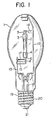
- a 50-watts, high-pressure sodium lamp with high color rendition shown in Fig. 1 has an outer jacket 1, which is evacuated and in which is disposed an arc tube 2.
- the arc tube 2 is a transparent alumina tube 4.1 mm in inner diameter and 0.8 mm in wall thickness.
- the end portions of the arc tube 2 are surrounded with heat-trapping foils 3 and 4 which have the function of trapping the heat and light radiated from electrodes to be described in detail below in the coldest spots in the tube between feed-throughs disposed behind the electrodes and the sealed ends of the arc tube 2, whereby the coldest spots may be maintained at high temperature.
- the pressure of sodium in the arc tube 2 can be maintained at high levels so that the self-reversal of D lines of sodium is enhanced and the width of every spectral line in the visible spectrum is increased.
- the high-pressure sodium lamp in accordance with the present invention realizes high color temperature and high color rendition as compared with the conventional HPS lamps.
- the pressure of sodium in the arc tube 2 can be varied over a relatively wide range depending upon the longitudinal or axial length of the heat trapping foils 3 and 4.
- the arc tube 2 is supported in the outer jacket or bulb 1 with support or lead-in wires 12 and 13 and an insulation rod 16.
- One end of a support plate 14 is welded to the support or lead-in wire 12 while the other end thereof, to the feed-through 5.
- One end of a support plate 15 is welded to the support or lead-in wire 13 while the other end thereof, to the lower end of the insulation rod 16.
- the other or upper end of the insulation rod 16 is loosely fitted into the feed-through 6.
- the support or lead-in wire 13 and the feed-through 6 are electrically interconnected with a lead wire 17.
- the support or lead-in wires 12 and 13 are extended through a glass stem 18 and are connected to the shell 20 and contact 21 of a base 19.
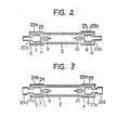
- Fig. 2 shows an arc tube for a 50-watts, high-pressure sodium lamp with high color rendition.
- the arc tube 2 is made of single-crystalline alumina and is 4.1 mm in inner diameter.
- the ends of the arc tube 2 are sealed with tubular feed-throughs 22 and 23 and ceramic cements 7 and 8.
- the enlarged-diameter portions 22a and 23a of the feed-throughs 22 and 23 which are made into very intimate contact with the inner cylindrical wall surface of the arc tube 2 have an outer diameter of 4 mm and the reduced-diameter portions 22b and 23b of the feed-throughs 22 and 23 which are located adjacent to the ends of the arc tube 2 have the outer diameter of 3 mm.
- the feed-throughs 22 and 23 are formed with the reduced-diameter portions 22b and 23b, respectively, as described above so that annular spaces may be provided between the reduced-diameter portions 22b and 23b and the inner cylindrical surface of the arc tube 2.
- ceramic cements 7 and 8 are heated and melted so as to seal the ends of the arc tube 2, they flow, due to capillarity, into the very narrow annular space about 0.05 mm in width between the enlarged-diameter portions 22a and 23a of the feed-throughs 22 and 23 and the inner cylindrical surface of the arc tube 2 so that they are securely bonded together.
- the molten cements 7 and 8 are not permitted to flow towards the end faces of the arc tube 2 and to fill the annular space defined between the reduced-diameter portions 22b and 23b of the feed-throughs 22 and 23 and the inner cylindrical wall surface of the arc tube 2. Consequently, when the ends of the arc tube 2 are sealed, the ceramic cements 7 and 8 are prevented from adhering to the inner cylindrical wall surface of the arc tube 2 behind the enlarged-diameter portions of the feed-throughs 22 and 23 and the annular end surfaces of the arc tube 2.
- the spacing between the inner cylindrical wall surfaces of the arc tube 2 and the reduced-diameter portions 22b and 23b of the feed-throughs 22 and 23 have been described as being 0.55 mm.
- the conditions for melting ceramic cement for sealing the ends of the arc tube 2 due to capillarity as described previously are dependent upon not only the spacing between the arc tube 2 and the reduced-diameter portions 22b and 23b of the feed-throughs 22 and 23 but also the properties of the cement used and a metal or alloy which is used as feed-throughs.
- the adhesion of the sealing cement to the annular end faces and their contiguous inner cylindrical wall surfaces of the arc tube 2 can be prevented if the spacing between the inner cylindrical wall surfaces of the arc tube 2 and the reduced-diameter portions 22b and 23b of the feed-throughs 22 and 23 is maintained greater than 0.2 mm.
- the feed-throughs 22 and 23 as shown in Fig. 2 are smaller both in surface area and cross section than tubular feed-throughs having uniform diameters.
- the thermal losses due to thermal radiation and conduction at the ends of the arc tube 2 as shown in Fig. 2 when the lamp is operated are considerably reduced and consequently the temperatures at the coldest points are further increased.
- the longitudinal or axial length of the heat trapping foils 3 and 4 which define the desired optical properties; that is, which maintain the sodium in the arc tube 2 at a predetermined pressure can be reduced.
- the fundamental function of the heat trapping foils 3 and 4 is to shield part of light produced by the discharge arc in the arc tube 2.
- Fig. 3 is shown a further example of an arc tube in accordance with the present invention for the 50-watts, high-pressure sodium lamp with high color rendition.
- This arc tube 2 is substantially similar in construction to the arctube shown in Fig. 2 except that the outer ends of the feed-throughs 24 and 25 are terminated into the enlarged-diameter portions 24c and 25c, respectively. That is, the feed-throughs 24 and 25 have the inner enlarged-diameter portions 24a and 25a, the intermediate reduced-diameter portions 24b and 25b and the outer enlarged-diameter portions 24c and 25c, respectively.
- the arc tube as shown in Fig. 3 can also attain the same effects and features as described previously in conjunction with the embodiment as shown in Fig. 2.
- the feed-throughs have been described as being made of niobium, but it is to be understood that the same inventors conducted extensive studies and experiments and confirmed the fact that even if the feed-throughs are made of other metals such as tantalium, zirconium, titanium or molybdenum, the propagation of cracks at the ends of the arc tube can be prevented.
- the costs of zirconium and titanium are especially lower than those of niobium and tantalium, so that the overall material costs of the arc tube can be reduced by about 25 to 35%.
- niobium may contain about 1 percent of zirconium and a titanium alloy containing a small amount of chromium, iron and/or aluminum may be used.
Landscapes
- Vessels And Coating Films For Discharge Lamps (AREA)
Claims (4)
caractérisée par le fait que
Applications Claiming Priority (6)
| Application Number | Priority Date | Filing Date | Title |
|---|---|---|---|
| JP82645/80 | 1980-06-17 | ||
| JP8264580A JPS579045A (en) | 1980-06-17 | 1980-06-17 | High pressure sodium lamp |
| JP13896980A JPS5763761A (en) | 1980-10-03 | 1980-10-03 | High pressure sodium lamp |
| JP138969/80 | 1980-10-03 | ||
| JP692481A JPS57121143A (en) | 1981-01-19 | 1981-01-19 | High pressure electric-discharge lamp |
| JP6924/81 | 1981-01-19 |
Publications (3)
| Publication Number | Publication Date |
|---|---|
| EP0042151A2 EP0042151A2 (fr) | 1981-12-23 |
| EP0042151A3 EP0042151A3 (en) | 1982-09-29 |
| EP0042151B1 true EP0042151B1 (fr) | 1985-09-04 |
Family
ID=27277397
Family Applications (1)
| Application Number | Title | Priority Date | Filing Date |
|---|---|---|---|
| EP81104515A Expired EP0042151B1 (fr) | 1980-06-17 | 1981-06-11 | Lampe à vapeur de sodium à haute pression |
Country Status (4)
| Country | Link |
|---|---|
| US (1) | US4423353A (fr) |
| EP (1) | EP0042151B1 (fr) |
| CA (1) | CA1162223A (fr) |
| DE (1) | DE3172126D1 (fr) |
Families Citing this family (6)
| Publication number | Priority date | Publication date | Assignee | Title |
|---|---|---|---|---|
| EP0115653B1 (fr) * | 1982-12-22 | 1988-11-09 | Koninklijke Philips Electronics N.V. | Lampe à décharge |
| EP0879122B1 (fr) | 1995-06-02 | 2006-02-22 | A.h. Casting Services Limited | Procede de preparation d'une matiere ceramique a haute densite et grande resistance aux chocs thermiques |
| US5680000A (en) * | 1995-11-07 | 1997-10-21 | Osram Sylvania Inc. | Reflective metal heat shield for metal halide lamps |
| US6873108B2 (en) | 2001-09-14 | 2005-03-29 | Osram Sylvania Inc. | Monolithic seal for a sapphire metal halide lamp |
| US20060211568A1 (en) * | 2005-03-16 | 2006-09-21 | Osram Sylvania Inc. | High Total Transmittance Alumina Discharge Vessels Having Submicron Grain Size |
| CN101828248B (zh) * | 2007-10-19 | 2012-02-22 | 奥斯兰姆有限公司 | 高压放电灯 |
Citations (1)
| Publication number | Priority date | Publication date | Assignee | Title |
|---|---|---|---|---|
| EP0041296A1 (fr) * | 1980-06-03 | 1981-12-09 | Koninklijke Philips Electronics N.V. | Lampe à décharge à haute pression |
Family Cites Families (8)
| Publication number | Priority date | Publication date | Assignee | Title |
|---|---|---|---|---|
| US3243635A (en) * | 1962-12-27 | 1966-03-29 | Gen Electric | Ceramic lamp construction |
| US3363134A (en) * | 1965-12-08 | 1968-01-09 | Gen Electric | Arc discharge lamp having polycrystalline ceramic arc tube |
| DE7030839U (de) * | 1969-08-18 | 1970-12-17 | Sylvania Electric Prod | Vorrichtung zum verschliessen der enden von elektrischen entladungsvorrichtungen. |
| JPS4893180A (fr) * | 1972-03-08 | 1973-12-03 | ||
| US3821587A (en) * | 1973-03-08 | 1974-06-28 | Westinghouse Electric Corp | Ceramic discharge lamp operable in air without an outer glass envelope |
| US3932782A (en) * | 1973-04-20 | 1976-01-13 | Gte Sylvania Incorporated | High pressure sodium vapor lamp having improved monolithic alumina arc tube |
| US3911313A (en) * | 1974-05-17 | 1975-10-07 | Gte Sylvania Inc | Electrode for arc discharge lamp |
| US4065691A (en) * | 1976-12-06 | 1977-12-27 | General Electric Company | Ceramic lamp having electrodes supported by crimped tubular inlead |
-
1981
- 1981-06-10 US US06/272,178 patent/US4423353A/en not_active Expired - Lifetime
- 1981-06-11 EP EP81104515A patent/EP0042151B1/fr not_active Expired
- 1981-06-11 DE DE8181104515T patent/DE3172126D1/de not_active Expired
- 1981-06-16 CA CA000379839A patent/CA1162223A/fr not_active Expired
Patent Citations (1)
| Publication number | Priority date | Publication date | Assignee | Title |
|---|---|---|---|---|
| EP0041296A1 (fr) * | 1980-06-03 | 1981-12-09 | Koninklijke Philips Electronics N.V. | Lampe à décharge à haute pression |
Also Published As
| Publication number | Publication date |
|---|---|
| EP0042151A3 (en) | 1982-09-29 |
| US4423353A (en) | 1983-12-27 |
| CA1162223A (fr) | 1984-02-14 |
| DE3172126D1 (en) | 1985-10-10 |
| EP0042151A2 (fr) | 1981-12-23 |
Similar Documents
| Publication | Publication Date | Title |
|---|---|---|
| US6215254B1 (en) | High-voltage discharge lamp, high-voltage discharge lamp device, and lighting device | |
| US3726582A (en) | Electric discharge lamp comprising container of densely sintered aluminum oxide | |
| KR970007293B1 (ko) | 만능 연소식 금속 할로겐화물 램프용의 유리질의 투광 아크 챔버 | |
| US4490642A (en) | High-pressure sodium discharge lamp | |
| US7030543B2 (en) | Reflector lamp having reduced seal temperature | |
| CA1122255A (fr) | Enveloppe de lampe en silice fusee et joint d'etancheite | |
| JPH0531801Y2 (fr) | ||
| EP0042151B1 (fr) | Lampe à vapeur de sodium à haute pression | |
| JP2802683B2 (ja) | メタルハライド放電ランプ | |
| JPH11144686A (ja) | 高圧放電ランプ及びその電極 | |
| EP0581354B1 (fr) | Lampe à décharge électrique à haute pression | |
| EP0720208B1 (fr) | Lampe fluorescente circulaire | |
| US4771207A (en) | Discharge lamp assembly | |
| JPH07240184A (ja) | セラミック放電灯およびこれを用いた投光装置ならびにセラミック放電灯の製造方法 | |
| US5576598A (en) | Lamp with glass sleeve and method of making same | |
| KR920010056B1 (ko) | 편밀봉형 금속증기 방전등 | |
| US6856079B1 (en) | Ceramic discharge lamp arc tube seal | |
| GB2080020A (en) | Electrical Light Source with a Metal Halide Discharge Tube and a Tungsten Filament Connected in Series with the Discharge Tube | |
| EP0204303A2 (fr) | Entrée de courant conique pour des températures élévées pour des lampes à décharge céramiques | |
| JP4022302B2 (ja) | メタルハライド放電ランプおよび照明装置 | |
| JPH0519255B2 (fr) | ||
| US7164232B2 (en) | Seal for ceramic discharge lamp arc tube | |
| GB2085650A (en) | High-pressure discharge lamp | |
| JP3911924B2 (ja) | 管球 | |
| JP2001345071A (ja) | 高圧放電ランプおよび照明装置 |
Legal Events
| Date | Code | Title | Description |
|---|---|---|---|
| PUAI | Public reference made under article 153(3) epc to a published international application that has entered the european phase |
Free format text: ORIGINAL CODE: 0009012 |
|
| 17P | Request for examination filed |
Effective date: 19810611 |
|
| AK | Designated contracting states |
Designated state(s): DE FR GB |
|
| PUAL | Search report despatched |
Free format text: ORIGINAL CODE: 0009013 |
|
| AK | Designated contracting states |
Designated state(s): DE FR GB |
|
| GRAA | (expected) grant |
Free format text: ORIGINAL CODE: 0009210 |
|
| AK | Designated contracting states |
Designated state(s): DE FR GB |
|
| REF | Corresponds to: |
Ref document number: 3172126 Country of ref document: DE Date of ref document: 19851010 |
|
| ET | Fr: translation filed | ||
| PLBE | No opposition filed within time limit |
Free format text: ORIGINAL CODE: 0009261 |
|
| STAA | Information on the status of an ep patent application or granted ep patent |
Free format text: STATUS: NO OPPOSITION FILED WITHIN TIME LIMIT |
|
| 26N | No opposition filed | ||
| PGFP | Annual fee paid to national office [announced via postgrant information from national office to epo] |
Ref country code: GB Payment date: 19950531 Year of fee payment: 15 |
|
| PGFP | Annual fee paid to national office [announced via postgrant information from national office to epo] |
Ref country code: DE Payment date: 19950607 Year of fee payment: 15 |
|
| PGFP | Annual fee paid to national office [announced via postgrant information from national office to epo] |
Ref country code: FR Payment date: 19950609 Year of fee payment: 15 |
|
| PG25 | Lapsed in a contracting state [announced via postgrant information from national office to epo] |
Ref country code: GB Effective date: 19960611 |
|
| GBPC | Gb: european patent ceased through non-payment of renewal fee |
Effective date: 19960611 |
|
| PG25 | Lapsed in a contracting state [announced via postgrant information from national office to epo] |
Ref country code: FR Effective date: 19970228 |
|
| PG25 | Lapsed in a contracting state [announced via postgrant information from national office to epo] |
Ref country code: DE Effective date: 19970301 |
|
| REG | Reference to a national code |
Ref country code: FR Ref legal event code: ST |