EP0042555A1 - Méthode de contrôle digital de l'enveloppe dans un instrument de synthèse musicale polyphonique, et circuits pour mettre en oeuvre cette méthode - Google Patents
Méthode de contrôle digital de l'enveloppe dans un instrument de synthèse musicale polyphonique, et circuits pour mettre en oeuvre cette méthode Download PDFInfo
- Publication number
- EP0042555A1 EP0042555A1 EP81104526A EP81104526A EP0042555A1 EP 0042555 A1 EP0042555 A1 EP 0042555A1 EP 81104526 A EP81104526 A EP 81104526A EP 81104526 A EP81104526 A EP 81104526A EP 0042555 A1 EP0042555 A1 EP 0042555A1
- Authority
- EP
- European Patent Office
- Prior art keywords
- envelope
- memory
- read
- address
- curve
- Prior art date
- Legal status (The legal status is an assumption and is not a legal conclusion. Google has not performed a legal analysis and makes no representation as to the accuracy of the status listed.)
- Granted
Links
Images


Classifications
-
- G—PHYSICS
- G10—MUSICAL INSTRUMENTS; ACOUSTICS
- G10H—ELECTROPHONIC MUSICAL INSTRUMENTS; INSTRUMENTS IN WHICH THE TONES ARE GENERATED BY ELECTROMECHANICAL MEANS OR ELECTRONIC GENERATORS, OR IN WHICH THE TONES ARE SYNTHESISED FROM A DATA STORE
- G10H1/00—Details of electrophonic musical instruments
- G10H1/02—Means for controlling the tone frequencies, e.g. attack or decay; Means for producing special musical effects, e.g. vibratos or glissandos
- G10H1/04—Means for controlling the tone frequencies, e.g. attack or decay; Means for producing special musical effects, e.g. vibratos or glissandos by additional modulation
- G10H1/053—Means for controlling the tone frequencies, e.g. attack or decay; Means for producing special musical effects, e.g. vibratos or glissandos by additional modulation during execution only
- G10H1/057—Means for controlling the tone frequencies, e.g. attack or decay; Means for producing special musical effects, e.g. vibratos or glissandos by additional modulation during execution only by envelope-forming circuits
- G10H1/0575—Means for controlling the tone frequencies, e.g. attack or decay; Means for producing special musical effects, e.g. vibratos or glissandos by additional modulation during execution only by envelope-forming circuits using a data store from which the envelope is synthesized
Definitions
- the invention relates to a method for digital envelope control of a polyphonic music synthesis instrument and a circuit arrangement for carrying out the method.
- Digitally operating electronic musical instruments so-called music synthesis instruments, are known and described, for example, in FR-OSes 79 15 337 and 80 03 892. They are based on the principle of synthesizing the frequencies to be heard by scanning phase counters and integrating the output pulses. This allows the audible frequencies to be generated polyphonically, although it can be assumed that eight tones can be played on the instrument at the same time. Under “tone” there should be a single fundamental frequency plus the harmonic content can be understood, which is typical of a traditional musical instrument to be simulated, for example.
- the harmonic component can comprise up to eight or even ten harmonics, and the individual frequencies are to be referred to here and hereinafter as "single tones". Wave shares a "tone" with five top 'accordingly comprises six “single notes.”
- the harmonic content is not the only criterion to be taken into account.
- the course of the envelope curve is equally important, ie the "attack” and “decay”, which in turn is typical of individual traditional musical instruments to be simulated; there are not only characteristic amplitude transitions, but also frequency variations, for example the typical vibrato in stringed instruments.
- a music synthesis instrument should therefore be able to generate up to 200 and more different envelopes at the same time in order to realize all musical possibilities and wishes.
- a circuit arrangement in which the envelopes of the overtones of a played fundamental can be varied is known from DE-OS 25 43 143.
- There the time duration for the tone up to a maximum value which can be set by switches and the time period for the decay up to a hold value which can also be influenced by the switch are stored in a tone color memory, and these values are read out in time multiplex and fed to a control unit.
- this circuit only a small storage capacity is required, but the range of variation is very limited, because only one - albeit frequently required - curve of the envelope can be generated; for other envelope shapes including amplitude and frequency modulation, repetition, modulations and so on you need more extensive and complex circuits.
- the object of the present invention is to provide a method for digital envelope control of a music synthesis instrument, in which the circuitry is reduced to a minimum, but nevertheless a large number of individual tones can be controlled independently of one another with regard to their envelope.
- the tinging and decaying of a tone normally follows an exponential function, since it is a matter of simulating transient processes which can take place periodically ("vibraphone") or aperiodically.
- the envelopes that are shown and to be generated have nothing to do with the volume that the player may be able to change arbitrarily, which would rather change the ordinate scale of the diagrams.
- Fig. 1a The simplest case is shown in Fig. 1a. From the time A onwards, the amplitude rises to the maximum amplitude H, following an exponential function in the aperiodic limit case, that is to say in accordance with a first envelope curve A 1 . The amplitude remains at this value until time R, from which the amplitude, again following an aperiodic exponential curve following envelope R 1 , drops to zero.
- a 1 and R 1 may be mirror images similar, they are stored separately in the read-only memory.
- Diagram 1b shows the case in which the memory already triggers the "end" command before the attack envelope has been run through to the nominal value H of the amplitude.
- the result is a shortened envelope envelope A 2 , which, however, must not follow the envelope envelope R 1 , since this would result in a jump in amplitude. Rather, the envelope curve A 2 must pass at least approximately exactly into a correspondingly shortened decay envelope curve R 2 . How this is done will be explained below.
- F ig. 1c shows an attack envelope A 3 , as is typical for a piano: the amplitude suddenly increases to a maximum value and then drops according to an exponential function. If the player lets go of the "piano key", the vibration is damped and curve A 3 must pass into the decay envelope R 3 without a jump in amplitude. This is a special case of diagram 1b.
- FIG. 1e Another form of envelope A S with overshoot is shown in Fig. 1e; this course is typical of brass.
- F ig. 1f shows a decay envelope R 5 with subaudio amplitude modulation: this envelope is required for vibraphone.
- Fig. 1g finally shows an attack envelope shape A 6 , which actually consists of the repeated repetition of one and the same curve shape, which can be recognized as A 3 with a shortened time scale.
- the circuit arrangement shown in FIG. 4 makes it possible to actually save only the curve shape A 3 and to repeat it several times.
- This attack envelope occurs, for example, with instruments such as mandolin or banjo.
- the associated decay envelope R 6 is the extension of the decay envelope A 6 to zero, starting from the amplitude value reached at R in each case.
- FIGS. 2a-2d represent the audio frequency in its temporal course.
- the same applies analogously to what was already stated for the scales in FIG. 1; it also applies here that the externally specified time scales can be used to call up the frequency swings recorded in the read-only memory at one and the same memory address.
- F ig. 2a shows an attack envelope A 7 ' in which the frequency f oscillates with a gradually increasing stroke around a carrier frequency f o . After a maximum stroke f max has been reached , the process is repeated as long as the sound is stored: so-called "normal delayed vibrato". As will be explained with reference to FIG. 4, it is also possible in this case to implement this envelope repetition with simple circuit measures.
- FIG. 2b shows a typical guitar envelope curve A 8 represents: Starting from a mild f ügig respect to the nominal frequency f o at high frequency falls this gradually to the value f according to which a similar trend followed as shown in Fig. 2a. 2c shows the approximately reversed course A 9 of the frequency when blowing on a brass instrument. FIG. 2d finally shows the chorus effect, that is to say the simultaneous sounding A 10 of several vibrations that are nominally of the same tuning, but in reality are slightly out of tune with one another.
- FIG. 3 shows, as three examples, further possible effects.
- FIG. 3a shows the so-called "Leslie effect" which arises when a loudspeaker is driven to rotate. The listener then has the impression that the frequency oscillates around the nominal frequency with a stroke f L in the sine curve.
- this effect can also be brought about by means of envelope control, in that two audio channels are controlled with a 180 o phase shift and the frequency deviation f L is introduced as a frequency modulation envelope.
- the envelope repetition is also possible with the circuit arrangement according to FIG. 4.
- Fig. 3b shows that this The Lesley effect can also be realized in a time-variable manner in accordance with the simulated "start-up” and “run-down” of a rotating loudspeaker, the frequency deviation F L also having to be varied.
- the harmony of several string instruments for example several guitars or a piano, in which several keys are assigned to each key, can be simulated by introducing a phase shift of 120 ° for the frequency modulation of each individual tone.
- This can also be achieved with the envelope control according to the invention, again using the envelope repetition technique.
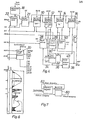
- Fig. 4 shows a block diagram of a circuit arrangement with which the method according to the invention can be carried out. It is assumed that there is a music synthesis instrument, for example according to the FR-OS mentioned at the beginning, with circuits in which a phase counter block is assigned to each individual tone and digital signals AMP or FRE can determine the respective envelope of the individual block in terms of amplitude or frequency.
- the single tone blocks work in time multiplex.
- Signals generated by the circuit arrangement include the number of the synthesis block in question (thus its address) and the envelope data AMP / FRE to be transmitted to this block (this address).
- Known parts of a music synthesis instrument are also provided on the input side of the circuit arrangement according to the invention, namely the operating elements for the player, such as manuals, pedals, switches, buttons, register adjusters and so on, as well as coding circles which result from the switch positions effected by these organs form associated control signals.
- the control signals are transmitted directly to the synthesis blocks, they can be disregarded here since they are not essential to the invention.
- the signals that are to be supplied to the envelope control according to the invention are to be explained.
- AD This is the current address which determines which synthesis block NR must receive the control signals from the envelope control circuit at the given time in the time-division multiplex frame.
- This digital value defines the real-time interval within which a predetermined (stored) envelope shape is to be traversed, that is to say that the abscissa scale for the processes according to FIGS. 1-3 is determined with this signal.
- FR-IN This digital value defines the frequency f in the case of frequency modulation envelopes. In a simple way, this input also serves
- the circuit is designed so that when FR-IN is zero, only amplitude modulation takes place.
- HK-IN This digital value indicates which envelope shape is to be used. As will be explained later, it takes the form of a read-only memory address, under which the start of the envelope curve scan is stored.
- MAN This signal indicates whether a certain single tone should be generated or not.
- the circuit is designed so that this signal is logic -0 if the tone is to be generated and logic -1 if it is to end.
- jump O-1 means the command for a decay envelope
- jump 1-O means the command for a decay envelope.
- ESA These are the connections for input and output signals of the control logic for the circuit arrangement.
- each random memory has 256 memory locations, all of which have homologous addresses.
- the addresses are the numbers of the corresponding sound synthesis circuit blocks.
- the four-microsecond clock was determined in consideration of the fact that for a musically satisfactory envelope curve development an envelope curve sample value has to be recalculated approximately every millisecond; this means that the 256 memory locations of the random memories should all be addressed once within this millisecond. This is almost achieved with four microseconds. With modern circuit components, this clock will be regarded as relatively slow.
- the addresses (AD) or the addresses output by the counter 18 run via a multiplexer 21 which has a control input SE. This is because it must be avoided that data are entered simultaneously because of AD and data is called up because of the counter addressing. For this reason, a BUSY signal is generated by means of comparator 22 for signals coming simultaneously from counter 18 and from AD, which then blocks multiplexer 22 for counter addressing via control logic unit 20.
- the binary words which have been entered as INT are stored in the random access memory 10.
- the random addresses 12 store the current addresses of envelope sample values stored in a read-only memory 24, specifically in the section HK-CT indicated on the left, where the "address amounts” of the read-only memory "to the left of the comma” are renewed.
- the "address fractions" of the read-only memory "to the right of the decimal point” are continuously adjusted.
- this desired real-time is stored in the random memory 10 in the form of an address fraction, that is to say as a complement.
- the envelope should last twice as long as the number of samples in the read-only memory on the one hand and the number of samples in the read-only memory on the other hand, the next sample is not called up for the next address pulse for this memory location, but only for the next but one, and so on .
- the circuit naturally works in the binary system, it is more descriptive to illustrate this sequence with decimal numbers.
- the fraction "0.25" is stored in the random access memory 10, which, according to the above, means that the envelope curve should last four times longer than normal.
- this variable is fed to an arithmetic logic unit 26 as an input. Your other input is the current value of HK-CT in the random access memory 12.
- the logic unit adds the fractional values, and the result of the addition is again entered as content into the random access memory 12 via the multiplexer 28, where a fraction increased by the value taken from the random access memory 10 is then written in "to the right of the decimal point" becomes.
- the address of the envelope curve samples in the read-only memory 24, on the other hand, are "integer".
- the next address for the read-only memory - in section HK-CT of the random access memory 12 - only appears after the address 18 has been addressed four times, which means that a changed sample value is only retrieved from the read-only memory after about four milliseconds , this is then called up four times in succession, only then the new address value is entered and so on.
- the start address of the read-only memory, under which the start of the envelope in question is stored, is of course first entered into the random memory 12 (signal HK-IN), namely via the multiplexer 28 under the control of the MU by the control logic unit 20, which in turn is based on the MAN signal reacts.
- the multiplexer is designed as a three-channel multiplexer.
- read-only memory addresses can also be entered “back” into the HK-CT section of the random access memory 12 by the read-only memory 24 itself.
- Read-only memory 24 between a distinction is made between the "addresses" of the memory locations and the "data” stored in these memory locations, or the content of the memory. Read-only memory 24 is addressed via line 30 and outputs the "data" on line 32.
- the stored data have the meaning of a read-only memory address if they are transmitted to the random access memory 12 via line branch 34 and via multiplexer 28. However, this is the exception; in general, the sample values of the envelope or - in the case of frequency modulation - the modulation stroke values are stored in the read-only memory 24).
- a signal EN is also output when an envelope has been completely called up from the read-only memory; this "end” signal causes the Logic unit 20 to delete the memory locations at the relevant address, after which - depending on the level of MAN - either the unmodulated tone continues to sound or the relevant single tone is no longer generated.
- "Unmodulated” naturally only refers to an envelope modulation introduced by the circuit according to FIG. 4; elsewhere in the overall circuit, other modulation of a "continuous tone" can also be carried out.
- this envelope data is fed to a two's complement binary adder 38.
- the envelope data are unsigned sample values in the case of pure amplitude modulation, and signed stroke values in the case of frequency modulation.
- the addition circuit 38 is signaled via line 40 whether frequency modulation is present or not - the associated carrier frequencies f o for each of the 256 envelopes to be generated are stored in the random access memory 16 (FR-IN) or zero if only amplitude modulation is required -, the envelope values belonging to the respective single tone appear at its output. These are to be fed to the amplitude modulation or frequency modulation blocks of the synthesis circuit.
- the assignment is made by the control logic unit 20 via a Gate 42 is then and only then a signal AM is supplied if it is amplitude modulation.
- the last sample value of the terminating envelope curve must therefore be recorded and the memory location of the continuing envelope curve where an at least approximately the same sample value is present must be sought in the read-only memory 24; the associated address must then be entered as the start address in the handheld memory 12.
- the circuit arrangement according to FIG. 4 has the random memory 14, in which the current sample value VL, which is present behind the adding circuit 38, is written for the memory location addressed in each case by counter 18.
- the same value VL is at an input of a comparator 50, at the other input of which is the immediately preceding value VL ', which is retrieved from the corresponding memory location when addressed by counter 18.
- the comparator delivers a logic signal at its output, here designated VLK, as long as the later sample value VL is smaller than the previous sample value VL '. This logic signal is fed to the control logic unit 20.
- the control logic unit only requires this information at the point in time at which a jump in the MAN signal indicates that a new envelope is required. It is initially assumed that a decay envelope is to be terminated by a MAN change from 1 to zero and to continue with a decay envelope. HK-IN then enters the associated read-only memory address, under which - as the initial sample value of an attack envelope - the sample value zero is called up. This appears after adding circuit 38 as a new value VL. However, since the word VL 'previously stored in random memory 14 originated from the aborted decay envelope and is therefore larger, the comparator 50 outputs the logic signal VLK.
- control logic unit 20 This now causes the control logic unit 20 to generate a control logic signal OP, which the arithmetic logic unit 26 does Command transmits to increase the saved address HK-CT of the read-only memory by one. This process is repeated with the system clock until the logic signal VLK changes because the comparator 50 can no longer determine a difference in size.
- the address HK-CT at this time in the random access memory 12 is then the "start address" of the continuing envelope.
- the complementary logic level VLK must initiate the "catch-up process"; the control logic unit 20 can make this distinction because it differentiates between jumps 0-1 and 1-0 for the MAN input.
- FIG. 5a and 5b summarize the processes described again.
- FIG. 5c shows the sequence when clocking counter 18 for the "normal case"; the associated explanation has already been given above.
- the organization of the read-only memory 24 is indicated schematically in FIG. 6.
- the envelope samples are drawn as analog equivalents, although of course it's actually binary words. From top to bottom, the envelopes "Slow response”, “Decay”, “Percussion with repetition” and “Delayed virbrato with repetition” are shown as examples.
- the first bit is the logic signal REp, the second bit the logic signal EN.
- the dash-dotted arrows in FIG. 6 indicate the address to which, for example, to return.
- the address at which an envelope curve begins is - as explained above - entered externally as HK-IN.
- control logic unit can comprise a further read-only memory 60, to which the above-mentioned logic signals are supplied as addresses and which is queried via a sequence register 62, which in turn is switched on by the system clock and into which the logic sequence to be run from the read-only memory itself is entered.
- the control signals required by the logic unit are then called up at its addresses.
- circuit arrangement shown and described is only a preferred exemplary embodiment and that the method can also be carried out with other, equivalent means.
- the circuit shown can be modified in such a way that the read-only memory 24 is replaced by a random memory into which the envelope data are entered externally.
- the arrangement is also not based on that limited only as examples of envelopes to be understood.
- the envelopes discussed so far would be generated in analog form by means of voltage-controlled amplifiers (amplitude modulation) or voltage-controlled oscillators (frequency modulation); With the circuit described, it is also possible to generate envelopes of the type which are implemented in analog circuits by voltage-controllable filters, including resonance phenomena and the like.
Landscapes
- Physics & Mathematics (AREA)
- Engineering & Computer Science (AREA)
- Acoustics & Sound (AREA)
- Multimedia (AREA)
- Electrophonic Musical Instruments (AREA)
Priority Applications (1)
| Application Number | Priority Date | Filing Date | Title |
|---|---|---|---|
| AT81104526T ATE7428T1 (de) | 1980-06-24 | 1981-06-12 | Verfahren zur digitalen huellkurvensteuerung eines polyphonen musiksyntheseinstruments und schaltungsanordnung zur durchfuehrung des verfahrens. |
Applications Claiming Priority (2)
| Application Number | Priority Date | Filing Date | Title |
|---|---|---|---|
| DE3023581A DE3023581C2 (de) | 1980-06-24 | 1980-06-24 | Verfahren zur digitalen Hüllkurvensteuerung eines polyphonen Musiksyntheseinstruments und Schaltungsanordnung zur Durchführung des Verfahrens |
| DE3023581 | 1980-06-24 |
Publications (2)
| Publication Number | Publication Date |
|---|---|
| EP0042555A1 true EP0042555A1 (fr) | 1981-12-30 |
| EP0042555B1 EP0042555B1 (fr) | 1984-05-09 |
Family
ID=6105334
Family Applications (1)
| Application Number | Title | Priority Date | Filing Date |
|---|---|---|---|
| EP81104526A Expired EP0042555B1 (fr) | 1980-06-24 | 1981-06-12 | Méthode de contrôle digital de l'enveloppe dans un instrument de synthèse musicale polyphonique, et circuits pour mettre en oeuvre cette méthode |
Country Status (6)
| Country | Link |
|---|---|
| US (1) | US4422363A (fr) |
| EP (1) | EP0042555B1 (fr) |
| JP (1) | JPS5748793A (fr) |
| AT (1) | ATE7428T1 (fr) |
| DE (2) | DE3023581C2 (fr) |
| SU (1) | SU1145940A3 (fr) |
Cited By (1)
| Publication number | Priority date | Publication date | Assignee | Title |
|---|---|---|---|---|
| EP0333451A1 (fr) * | 1988-03-17 | 1989-09-20 | Roland Corporation | Instrument de musique électronique |
Families Citing this family (15)
| Publication number | Priority date | Publication date | Assignee | Title |
|---|---|---|---|---|
| JPS59173097U (ja) * | 1983-05-09 | 1984-11-19 | 株式会社ケンウッド | 楽音合成回路 |
| JPS6022185A (ja) * | 1983-07-18 | 1985-02-04 | 松下電器産業株式会社 | ビブラ−ト信号発生装置 |
| JPS6060693A (ja) * | 1983-09-14 | 1985-04-08 | ヤマハ株式会社 | 電子楽器 |
| JP2642331B2 (ja) * | 1984-08-09 | 1997-08-20 | カシオ計算機株式会社 | ビブラート付与装置 |
| JPS61128296A (ja) * | 1984-11-27 | 1986-06-16 | ヤマハ株式会社 | 楽音発生装置 |
| JPS61188593A (ja) * | 1985-02-18 | 1986-08-22 | カシオ計算機株式会社 | タツチレスポンス装置 |
| JPS62186296A (ja) * | 1986-02-12 | 1987-08-14 | 京王技研工業株式会社 | エンベロ−プ発生装置 |
| JPH0731501B2 (ja) * | 1986-08-08 | 1995-04-10 | カシオ計算機株式会社 | タッチデータ生成装置 |
| JPH0720713Y2 (ja) * | 1986-08-08 | 1995-05-15 | カシオ計算機株式会社 | タッチデータ生成装置 |
| US5200567A (en) * | 1986-11-06 | 1993-04-06 | Casio Computer Co., Ltd. | Envelope generating apparatus |
| US5548080A (en) * | 1986-11-06 | 1996-08-20 | Casio Computer Co., Ltd. | Apparatus for appoximating envelope data and for extracting envelope data from a signal |
| US4928569A (en) * | 1986-11-15 | 1990-05-29 | Yamaha Corporation | Envelope shape generator for tone signal control |
| KR920000764B1 (ko) * | 1988-05-18 | 1992-01-21 | 삼성전자 주식회사 | 전자악기의 adsr데이터 출력 제어시스템 |
| US5256831A (en) * | 1990-07-10 | 1993-10-26 | Yamaha Corporation | Envelope waveform generation apparatus |
| US20130163787A1 (en) * | 2011-12-23 | 2013-06-27 | Nancy Diane Moon | Electronically Orbited Speaker System |
Citations (4)
| Publication number | Priority date | Publication date | Assignee | Title |
|---|---|---|---|---|
| US3610805A (en) * | 1969-10-30 | 1971-10-05 | North American Rockwell | Attack and decay system for a digital electronic organ |
| DE2715510A1 (de) * | 1976-04-06 | 1977-10-13 | Nippon Musical Instruments Mfg | Elektronisches musikinstrument |
| US4185532A (en) * | 1976-09-29 | 1980-01-29 | Nippon Gakki Seizo Kabushiki Kaisha | Envelope generator |
| DE3003385A1 (de) * | 1979-01-31 | 1980-08-07 | Kawai Musical Instr Mfg Co | Elektronisches musikinstrument |
Family Cites Families (4)
| Publication number | Priority date | Publication date | Assignee | Title |
|---|---|---|---|---|
| US3930429A (en) * | 1973-06-08 | 1976-01-06 | Arp Instruments, Inc. | Digital music synthesizer |
| US4083285A (en) * | 1974-09-27 | 1978-04-11 | Nippon Gakki Seizo Kabushiki Kaisha | Electronic musical instrument |
| JPS5237028A (en) * | 1975-09-17 | 1977-03-22 | Nippon Gakki Seizo Kk | Electronical music instrument |
| US4166405A (en) * | 1975-09-29 | 1979-09-04 | Nippon Gakki Seizo Kabushiki Kaisha | Electronic musical instrument |
-
1980
- 1980-06-24 DE DE3023581A patent/DE3023581C2/de not_active Expired
-
1981
- 1981-06-12 AT AT81104526T patent/ATE7428T1/de active
- 1981-06-12 DE DE8181104526T patent/DE3163483D1/de not_active Expired
- 1981-06-12 EP EP81104526A patent/EP0042555B1/fr not_active Expired
- 1981-06-22 JP JP56096433A patent/JPS5748793A/ja active Pending
- 1981-06-23 US US06/276,685 patent/US4422363A/en not_active Expired - Fee Related
- 1981-06-24 SU SU813305849A patent/SU1145940A3/ru active
Patent Citations (4)
| Publication number | Priority date | Publication date | Assignee | Title |
|---|---|---|---|---|
| US3610805A (en) * | 1969-10-30 | 1971-10-05 | North American Rockwell | Attack and decay system for a digital electronic organ |
| DE2715510A1 (de) * | 1976-04-06 | 1977-10-13 | Nippon Musical Instruments Mfg | Elektronisches musikinstrument |
| US4185532A (en) * | 1976-09-29 | 1980-01-29 | Nippon Gakki Seizo Kabushiki Kaisha | Envelope generator |
| DE3003385A1 (de) * | 1979-01-31 | 1980-08-07 | Kawai Musical Instr Mfg Co | Elektronisches musikinstrument |
Cited By (2)
| Publication number | Priority date | Publication date | Assignee | Title |
|---|---|---|---|---|
| EP0333451A1 (fr) * | 1988-03-17 | 1989-09-20 | Roland Corporation | Instrument de musique électronique |
| US5094138A (en) * | 1988-03-17 | 1992-03-10 | Roland Corporation | Electronic musical instrument |
Also Published As
| Publication number | Publication date |
|---|---|
| DE3163483D1 (en) | 1984-06-14 |
| DE3023581A1 (de) | 1982-01-07 |
| JPS5748793A (en) | 1982-03-20 |
| US4422363A (en) | 1983-12-27 |
| DE3023581C2 (de) | 1983-11-10 |
| SU1145940A3 (ru) | 1985-03-15 |
| ATE7428T1 (de) | 1984-05-15 |
| EP0042555B1 (fr) | 1984-05-09 |
Similar Documents
| Publication | Publication Date | Title |
|---|---|---|
| EP0042555B1 (fr) | Méthode de contrôle digital de l'enveloppe dans un instrument de synthèse musicale polyphonique, et circuits pour mettre en oeuvre cette méthode | |
| DE3528719C2 (fr) | ||
| DE3936693C2 (de) | Vorrichtung zum Erzeugen digitaler Audiosignale | |
| DE3221447C2 (fr) | ||
| DE2712226A1 (de) | Tongeneratoranordnung, insbesondere fuer ein elektronisches musikinstrument | |
| DE3015455C2 (fr) | ||
| DE3689928T2 (de) | Effektvorrichtung für elektronisches Musikinstrument. | |
| DE3049294A1 (de) | Automatisches rhythmusbegleitsystem | |
| DE3630611C2 (fr) | ||
| DE3032609A1 (de) | Elektronisches tastenmusikinstrument mit mehreren tonerzeugungskanaelen. | |
| DE2920298A1 (de) | Binaere interpolatorschaltung fuer ein elektronisches musikinstrument | |
| DE2526457C3 (de) | Elektronisches Musikinstrument | |
| DE2828919C2 (de) | Schaltungsanordnung für ein polyphones elektronisches Musikinstrument | |
| DE2937256A1 (de) | Digitales elektronisches musikinstrument | |
| DE3605122C2 (fr) | ||
| DE3785625T2 (de) | Tonerzeugungsvorrichtung mit Wellenformspeicher. | |
| EP0036074B1 (fr) | Synthétiseur de signaux périodiques, en particulier pour instrument de musique | |
| DE2513127C2 (de) | Verfahren zum künstlichen Erzeugen eines musikalischen Klangs | |
| DE69521731T2 (de) | Tonsignalerzeuger mit einer Klangeffektfunktion | |
| DE2915678A1 (de) | Elektronisches musikinstrument | |
| DE4232642B4 (de) | Solenoid-Ansteuersystem für ein Gerät zur automatischen musikalischen Darbietung | |
| DE3150074C2 (de) | Schaltung zum Erzeugen von Musiktönen | |
| DE2901969A1 (de) | Elektronisches musikinstrument mit einer einrichtung zur erzeugung variabler impulse | |
| DE3604686A1 (de) | Elektronisches musikinstument | |
| DE2952459C2 (fr) |
Legal Events
| Date | Code | Title | Description |
|---|---|---|---|
| PUAI | Public reference made under article 153(3) epc to a published international application that has entered the european phase |
Free format text: ORIGINAL CODE: 0009012 |
|
| AK | Designated contracting states |
Designated state(s): AT DE FR GB IT NL |
|
| 17P | Request for examination filed |
Effective date: 19820121 |
|
| RAP1 | Party data changed (applicant data changed or rights of an application transferred) |
Owner name: MATTH. HOHNER AG |
|
| ITF | It: translation for a ep patent filed | ||
| GRAA | (expected) grant |
Free format text: ORIGINAL CODE: 0009210 |
|
| AK | Designated contracting states |
Designated state(s): AT DE FR GB IT NL |
|
| PGFP | Annual fee paid to national office [announced via postgrant information from national office to epo] |
Ref country code: DE Payment date: 19840509 Year of fee payment: 4 |
|
| REF | Corresponds to: |
Ref document number: 7428 Country of ref document: AT Date of ref document: 19840515 Kind code of ref document: T |
|
| REF | Corresponds to: |
Ref document number: 3163483 Country of ref document: DE Date of ref document: 19840614 |
|
| PGFP | Annual fee paid to national office [announced via postgrant information from national office to epo] |
Ref country code: FR Payment date: 19840618 Year of fee payment: 4 |
|
| ET | Fr: translation filed | ||
| PLBE | No opposition filed within time limit |
Free format text: ORIGINAL CODE: 0009261 |
|
| STAA | Information on the status of an ep patent application or granted ep patent |
Free format text: STATUS: NO OPPOSITION FILED WITHIN TIME LIMIT |
|
| 26N | No opposition filed | ||
| PGFP | Annual fee paid to national office [announced via postgrant information from national office to epo] |
Ref country code: AT Payment date: 19850613 Year of fee payment: 5 |
|
| PG25 | Lapsed in a contracting state [announced via postgrant information from national office to epo] |
Ref country code: AT Effective date: 19860612 |
|
| PGFP | Annual fee paid to national office [announced via postgrant information from national office to epo] |
Ref country code: NL Payment date: 19860630 Year of fee payment: 6 |
|
| PG25 | Lapsed in a contracting state [announced via postgrant information from national office to epo] |
Ref country code: NL Effective date: 19880101 |
|
| NLV4 | Nl: lapsed or anulled due to non-payment of the annual fee | ||
| PG25 | Lapsed in a contracting state [announced via postgrant information from national office to epo] |
Ref country code: FR Free format text: LAPSE BECAUSE OF NON-PAYMENT OF DUE FEES Effective date: 19880226 |
|
| PG25 | Lapsed in a contracting state [announced via postgrant information from national office to epo] |
Ref country code: DE Effective date: 19880301 |
|
| GBPC | Gb: european patent ceased through non-payment of renewal fee | ||
| REG | Reference to a national code |
Ref country code: FR Ref legal event code: ST |
|
| PG25 | Lapsed in a contracting state [announced via postgrant information from national office to epo] |
Ref country code: GB Effective date: 19881118 |