EP0042557A2 - Appareil pour doser des matériaux à fluidité faible - Google Patents
Appareil pour doser des matériaux à fluidité faible Download PDFInfo
- Publication number
- EP0042557A2 EP0042557A2 EP81104546A EP81104546A EP0042557A2 EP 0042557 A2 EP0042557 A2 EP 0042557A2 EP 81104546 A EP81104546 A EP 81104546A EP 81104546 A EP81104546 A EP 81104546A EP 0042557 A2 EP0042557 A2 EP 0042557A2
- Authority
- EP
- European Patent Office
- Prior art keywords
- metering
- cylinder
- piston
- line
- dosing
- Prior art date
- Legal status (The legal status is an assumption and is not a legal conclusion. Google has not performed a legal analysis and makes no representation as to the accuracy of the status listed.)
- Withdrawn
Links
- 239000000463 material Substances 0.000 title claims abstract description 33
- 239000003973 paint Substances 0.000 claims abstract description 4
- 230000006835 compression Effects 0.000 claims description 8
- 238000007906 compression Methods 0.000 claims description 8
- 238000012806 monitoring device Methods 0.000 claims description 7
- 238000011144 upstream manufacturing Methods 0.000 claims description 4
- 238000012544 monitoring process Methods 0.000 claims 2
- 230000009969 flowable effect Effects 0.000 description 3
- 239000012530 fluid Substances 0.000 description 2
- 239000003999 initiator Substances 0.000 description 2
- 239000000049 pigment Substances 0.000 description 2
- 239000003086 colorant Substances 0.000 description 1
- 230000008878 coupling Effects 0.000 description 1
- 238000010168 coupling process Methods 0.000 description 1
- 238000005859 coupling reaction Methods 0.000 description 1
- 238000004806 packaging method and process Methods 0.000 description 1
- 230000036316 preload Effects 0.000 description 1
- 239000002904 solvent Substances 0.000 description 1
- 239000002966 varnish Substances 0.000 description 1
Images

Classifications
-
- G—PHYSICS
- G01—MEASURING; TESTING
- G01F—MEASURING VOLUME, VOLUME FLOW, MASS FLOW OR LIQUID LEVEL; METERING BY VOLUME
- G01F11/00—Apparatus requiring external operation adapted at each repeated and identical operation to measure and separate a predetermined volume of fluid or fluent solid material from a supply or container, without regard to weight, and to deliver it
- G01F11/02—Apparatus requiring external operation adapted at each repeated and identical operation to measure and separate a predetermined volume of fluid or fluent solid material from a supply or container, without regard to weight, and to deliver it with measuring chambers which expand or contract during measurement
- G01F11/021—Apparatus requiring external operation adapted at each repeated and identical operation to measure and separate a predetermined volume of fluid or fluent solid material from a supply or container, without regard to weight, and to deliver it with measuring chambers which expand or contract during measurement of the piston type
Definitions
- the invention relates to a metering device according to the preamble of claim 1.
- Dosing devices of this type with upstream conveyor systems have proven themselves in practice; but they have the fundamental disadvantage that each roller mill must have its own conveyor system and its own metering device. Dosing devices of this type with upstream conveyor systems are therefore only economically usable where the same material, for example the same color, is produced over a very long period of time, and in such an amount that such a metering device is sufficiently utilized. In companies with frequent material changes or numerous small roller mills, however, such devices cannot be used or cannot be used economically.
- the invention is therefore based on the object of providing a metering device of the generic type, by means of which the material can also be picked up and metered from numerous roller mills or the like, without intermediate conveyance being necessary.
- This object is achieved by the characterizing features of claim 1.
- the essence of the invention is that the dosing device has been completely independent, i. H. by moving away from the pressure delivery principle by means of a separate conveyor system to the suction-delivery principle with delivery by means of the metering piston, the use of a separate conveyor system became superfluous. The fact that the unit is made independent and mobile, it can be used at any time in different places. Finally, a separate storage container is assigned to it, into which the material flows freely from the roller mill or the like, from which it is then sucked into the metering cylinder.
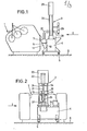
- a mobile metering device 3 is arranged downstream of a roller mill 1, the rollers 2 of which are only indicated in the drawing.
- roller mills in particular the three-roller chair shown in the drawing, are generally known and have been used in particular in the paint industry for decades to finely grind pigments, the colors or other materials ver ver the roller mill in a difficult to flow condition to let. These materials, which are difficult to flow (but still flowable), are fed to the metering device 3 for metering and subsequent filling in each case of precisely metered quantities in packaging containers.
- the metering device 3 has a box-shaped base frame 4 which is supported against the floor 6 in a freely movable manner by means of rollers 5.
- the devices required for the operation of the metering device such as a hydraulic pump unit, control devices and the like, are accommodated, so that the device can be used anywhere if only an electrical power connection is available.
- the base frame At the rear of the base frame there is an approximately funnel-shaped storage container 7, which is supported by means of holding pins 8 in slots 9, which are open at the top, of a bearing block 11 attached to the rear wall 10 of the base frame.
- the holding pin 8 and correspondingly the slots 9 are formed in the vicinity of the rear wall 10.
- the bottom 12 of the storage container 7 On the side facing away from the rear wall 10, the bottom 12 of the storage container 7 is still supported on a fill level monitoring device 13, which forms the third support point of the storage container 7.
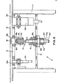
- the device 13 has a lower abutment 14 and an upper abutment 15, both of which are fastened to the bearing block 11.
- a clamping screw 16 is adjustably attached in its longitudinal direction by means of a thread 16a, against which a prestressable helical compression spring 17 is supported.
- This helical compression spring 17 is supported with its upper end against a support pin 18 which through a bore 18a in the upper Abutment 15 engages and is supported with a stop collar 18b against the upper abutment 15.
- the reservoir 7 rests with its base 12 on the top of the support pin 18.
- the compression spring 17 is pretensioned in such a way that the tension screw 16 is adjusted in height by turning relative to the lower abutment 14, as a result of which the collar 18c on the tension screw 16, against which the compression spring 17 rests, is also adjusted in height.
- the clamping screw 16 is secured relative to the lower abutment 14 by a lock nut 16b screwed onto the thread 16a.
- the fill level monitoring device 13 is also a contactless working initiator, i. H. Limit switch 18d assigned, which penetrates a bore 18e in the upper abutment 15. If the weight of the reservoir 7, d. H. the weight of the material filling contained in it exceeds a certain value, which is predetermined by the pretension of the compression spring 17, then the storage container 7 presses the pivot pin 18 against the force of the compression spring 17, pivoting about the retaining pin 8, causing the limit switch 18d to give a signal triggers, which is evaluated in the manner to be explained below.
- a contactless working initiator i. H. Limit switch 18d assigned
- an adjusting screw 18f is arranged adjustable in length by means of a thread 18g. You can by means of a Thread 18g screwed lock nut 18h are secured in position relative to the clamping screw 16.
- a second, relatively stiff, non-preloaded further helical spring 18i is arranged on the adjusting screw 18f and is guided in a blind hole recess 18j on the underside of the support pin 18. In the rest position shown in FIG. 6, its upper end is free from the bottom 18k of the recess 18j. The distance between the associated end of the coil spring 18i and the bottom 18k of the recess 18j can be adjusted by means of the adjusting screw 18f.
- a second initiator which is also adjustable in height, ie a second contact-free limit switch 181, which likewise penetrates a bore 18m in the upper abutment 15. If the weight of the material in the storage container 7 significantly exceeds the above-described minimum weight, then the support pin is pressed down so far that the second coil spring 18i comes into engagement, whereby the overall spring system consisting of the compression spring 17 and the coil spring 18i very much becomes stiffer. When the storage container 7 is deflected further, the limit switch 181 then emits a signal which is evaluated in the manner to be explained further below.
- the actual dosing device is attached to the base frame 4. It has a vertically arranged metering cylinder 19, in which a metering piston 2o is arranged, which in turn is attached to the free end of a length-adjustable piston rod 21 of a hydraulically actuated piston-cylinder drive 22.
- This drive 22 is essentially housed in a housing 23, which by means of four columns 24 on the lower frame 4 is supported, wherein the metering cylinder 19 is supported between the columns 24 on the top 25 of the base frame 4.
- the dosing cylinder 19 has a three-way valve 26 in its lower region, which is connected on the one hand to the storage container 7 via a suction line 27 and on the other hand is connected to a filling valve 29 by means of a pressure line 28.
- the third way of the valve 26 leads into the metering cylinder 19.
- the suction line 27 and the pressure line 28 with filling valve 29 are each connected to the corresponding connections of the valve 26 by means of quick couplings 30.
- the valve 26 is optionally adjustable for suction or pushing out.
- a so-called rotary plug 31 is turned into the position shown in FIG. 4, in which the pressure line 28 is closed, while the suction line 27 is connected to the metering cylinder 19.
- the piston rod 21 and thus the metering piston 20 are moved upward and sucks a corresponding amount of flowable material from the reservoir 7 according to the arrow 32 into the metering cylinder.
- the path length over which the piston rod 21 and thus also the metering piston 20 is moved is predetermined by a corresponding length adjustment of the piston rod 21. In other words, this means that the starting position of the metering piston 2o is determined by the corresponding length setting.
- the intake stroke is limited by an internal stop in the hydraulic cylinder 22.
- the rotary plug 31 is rotated into the position shown in FIG. 5, in which it closes the suction line 27 but releases the pressure line 28.
- the drive 22 is acted upon by hydraulic fluid acting downwards, so that the material located in the metering cylinder 19 by means of the metering piston 2o via the pressure line 28 and the filling valve 29 is pushed out.
- a non-contact limit switch 33 is attached in a height-adjustable manner, to which a contactor 34 attached to the piston rod 21 is assigned. When the latter reaches the limit switch 33, the filling valve 29 is closed and the metering stroke is ended.
- the fill level monitoring device 13 is set in such a way that the limit switch 18d emits a signal when the material fill that can be sucked in via the suction line 27 is at least as large as a - predetermined - fill of the metering cylinder 19, of course only the amount of material that is located above the suction opening 36 of the suction line 27 is taken into account. Only when the signal indicating the corresponding quantity in the storage container 7 comes from this limit switch is the circuit controlling the filling stroke for the metering cylinder 19 released.
- the dosing cylinder 19 is fastened by means of locking screws 37 which are easily detachable, so that it can itself be quickly replaced by another dosing cylinder.
Landscapes
- Physics & Mathematics (AREA)
- Fluid Mechanics (AREA)
- General Physics & Mathematics (AREA)
- Basic Packing Technique (AREA)
- Coating Apparatus (AREA)
- Feeding, Discharge, Calcimining, Fusing, And Gas-Generation Devices (AREA)
Applications Claiming Priority (2)
| Application Number | Priority Date | Filing Date | Title |
|---|---|---|---|
| DE19803023003 DE3023003A1 (de) | 1980-06-20 | 1980-06-20 | Dosiergeraet fuer schwer fliessfaehige materialien |
| DE3023003 | 1980-06-20 |
Publications (2)
| Publication Number | Publication Date |
|---|---|
| EP0042557A2 true EP0042557A2 (fr) | 1981-12-30 |
| EP0042557A3 EP0042557A3 (fr) | 1984-03-21 |
Family
ID=6104985
Family Applications (1)
| Application Number | Title | Priority Date | Filing Date |
|---|---|---|---|
| EP81104546A Withdrawn EP0042557A3 (fr) | 1980-06-20 | 1981-06-12 | Appareil pour doser des matériaux à fluidité faible |
Country Status (5)
| Country | Link |
|---|---|
| US (1) | US4402428A (fr) |
| EP (1) | EP0042557A3 (fr) |
| JP (1) | JPS5766318A (fr) |
| DE (1) | DE3023003A1 (fr) |
| ES (1) | ES503145A0 (fr) |
Cited By (2)
| Publication number | Priority date | Publication date | Assignee | Title |
|---|---|---|---|---|
| DE3412628A1 (de) * | 1984-04-04 | 1985-10-17 | Benz & Hilgers GmbH, 4000 Düsseldorf | Vorrichtung zum dosierten abfuellen von fliessfaehigem fuellgut in behaelter |
| FR2789735A1 (fr) * | 1999-02-11 | 2000-08-18 | Jean Croizer | Pompe doseuse volumetrique |
Families Citing this family (11)
| Publication number | Priority date | Publication date | Assignee | Title |
|---|---|---|---|---|
| FR2511149A1 (fr) * | 1981-08-04 | 1983-02-11 | Roussel Uclaf | Dispositif et procede de dosage de quantites predeterminees d'au moins un produit |
| DE3327420A1 (de) * | 1983-07-29 | 1985-02-07 | Ludwig Schwerdtel GmbH, 8047 Karlsfeld | Dosiergeraet zum dosieren einer hauptmasse und mindestens eines zuschlagstoffes, insbesondere zum dosieren hochviskoser massen |
| DE3840972A1 (de) * | 1988-05-18 | 1989-11-30 | Groninger & Co Gmbh | Pumpvorrichtung |
| US7584770B2 (en) * | 2006-01-30 | 2009-09-08 | Stainless Specialists, Inc. | Integrated product filler |
| US20080067192A1 (en) * | 2006-09-15 | 2008-03-20 | Stanton Jennifer L | Viscous material feed system and method |
| US7793802B2 (en) * | 2006-09-15 | 2010-09-14 | Momentive Performance Materials | Fastener for a viscous material container evacuator and method |
| US7784503B2 (en) * | 2006-09-29 | 2010-08-31 | Momentive Performance Materials | Viscous material metering system and method |
| US7610167B2 (en) * | 2006-11-08 | 2009-10-27 | Momentive Performance Materials | Controlled material processing device, controller and method |
| US7600658B2 (en) * | 2006-11-28 | 2009-10-13 | Momentive Performance Materials | Viscous material feed system with platen and method |
| AU2019265238A1 (en) * | 2018-05-10 | 2021-01-07 | Acasti Pharma, Inc. | Apparatus for metering and dispensing viscous substance |
| CN113307212B (zh) * | 2021-05-26 | 2022-06-24 | 江苏汤姆智能装备有限公司 | 一种灌压一体机及其灌压方法 |
Family Cites Families (8)
| Publication number | Priority date | Publication date | Assignee | Title |
|---|---|---|---|---|
| FR1397296A (fr) * | 1964-03-03 | 1965-04-30 | Bonnet Ets | Diviseur volumétrique à débit continu |
| US3306495A (en) * | 1964-06-02 | 1967-02-28 | American Motors Corp | Dispensing apparatus with calibrating means |
| FR1409184A (fr) * | 1964-09-28 | 1965-08-20 | J De Vree & Co P V B A | Dispositif de dosage perfectionné pour le remplissage de récipients, tels que des boîtes métalliques ou non, des flacons ou tous récipients similaires |
| CH582879A5 (en) * | 1974-03-29 | 1976-12-15 | Eggler Robert | Automatic drink dispenser warning system - gives two-stage indication of imminent emptying of liquid container |
| JPS5225268A (en) * | 1975-08-20 | 1977-02-25 | Tdk Electronics Co Ltd | Device for feeding electronic parts automatically |
| US4170253A (en) * | 1976-04-19 | 1979-10-09 | Mcarthur Donald A | Bakery mix dispenser having pump actuated outlet gate |
| DE2729539A1 (de) * | 1977-06-30 | 1979-01-11 | Donald Adrian Mcarthur | Dosiergeraet |
| US4228924A (en) * | 1978-08-23 | 1980-10-21 | Gilbert Charles H | Mixture metering machine |
-
1980
- 1980-06-20 DE DE19803023003 patent/DE3023003A1/de not_active Withdrawn
-
1981
- 1981-03-17 US US06/244,822 patent/US4402428A/en not_active Expired - Fee Related
- 1981-06-08 JP JP56087020A patent/JPS5766318A/ja active Pending
- 1981-06-12 EP EP81104546A patent/EP0042557A3/fr not_active Withdrawn
- 1981-06-17 ES ES503145A patent/ES503145A0/es active Granted
Cited By (2)
| Publication number | Priority date | Publication date | Assignee | Title |
|---|---|---|---|---|
| DE3412628A1 (de) * | 1984-04-04 | 1985-10-17 | Benz & Hilgers GmbH, 4000 Düsseldorf | Vorrichtung zum dosierten abfuellen von fliessfaehigem fuellgut in behaelter |
| FR2789735A1 (fr) * | 1999-02-11 | 2000-08-18 | Jean Croizer | Pompe doseuse volumetrique |
Also Published As
| Publication number | Publication date |
|---|---|
| ES8204170A1 (es) | 1982-04-16 |
| JPS5766318A (en) | 1982-04-22 |
| ES503145A0 (es) | 1982-04-16 |
| DE3023003A1 (de) | 1982-01-14 |
| US4402428A (en) | 1983-09-06 |
| EP0042557A3 (fr) | 1984-03-21 |
Similar Documents
| Publication | Publication Date | Title |
|---|---|---|
| EP0042557A2 (fr) | Appareil pour doser des matériaux à fluidité faible | |
| DE102004010774B4 (de) | Materialzuführsystem | |
| DE3911694A1 (de) | Vorrichtung zur zufuhr von harzmaterial zu einer kunstharz-formteilpresse | |
| DE3421581C2 (fr) | ||
| DE2312647A1 (de) | Dosierpumpe, insbesondere zum dosieren mehrerer kunstoffkomponenten | |
| EP0206073A2 (fr) | Dispositif de dosage à piston pour la fabrication d'une matière plastique, en particulier d'un mélange de réaction apte à couler d'au moins deux composants de réaction aptes à couler pour former une mousse | |
| DE19530296B4 (de) | Vorrichtung zum schichtweisen Herstellen eines Objektes | |
| DE2741943C2 (de) | Absenkvorrichtung | |
| DE2300972C3 (de) | Einrichtung zum automatischen Überwachen und Einregeln des Luftdruckes bei Pneumatikvorrichtungen | |
| DE2218864C3 (de) | Vorrichtung zum dosierten Abfüllen von Flüssigkeiten wie Milch u.dgl | |
| DE2424967C3 (de) | Steuervorrichtung für den Hebemechanismus eines Kippfahrzeuges zum Einstellen des Drehwinkels der Mulde eines Muldentransporters | |
| DE2415427C2 (de) | Einfüllmaschine für polymere Substanzen bei einer Formungseinrichtung | |
| DE10258243B4 (de) | Vorrichtung zum Aufbringen eines Produkts auf eine Unterlage | |
| DE102010004068B4 (de) | Verfahren und Befüllvorrichtung zum Befüllen einer Kartusche mit zumindest einem Material | |
| DE2936056C2 (de) | Dosiervorrichtung für Flüssigkeiten | |
| EP0484705A1 (fr) | Dispositif pour le remplissage de saucisses | |
| DE8027473U1 (de) | Brikettpresse | |
| EP0028806B1 (fr) | Tête à mouler multiple | |
| DE2953952C2 (fr) | ||
| DE2028962A1 (de) | Abfüllvorrichtung für zähviskose Pasten, Verfahren zum dosierten Abgeben einer zähviskosen Paste und Dosiervorrichtung zur Durchführung dieses Verfahrens | |
| DE2137278B2 (de) | Absperrschieber fuer fuellmaschinen | |
| DE1145084B (de) | Abfuell- und Dosiereinrichtung fuer Fluessigkeiten, Pasten oder aehnliche Stoffe | |
| DE3241042C2 (fr) | ||
| EP1644275A1 (fr) | Dispositif d'amenee de pieces de petites dimensions | |
| DE2409771A1 (de) | Einrichtung zum spritzen von keramischen massen |
Legal Events
| Date | Code | Title | Description |
|---|---|---|---|
| PUAI | Public reference made under article 153(3) epc to a published international application that has entered the european phase |
Free format text: ORIGINAL CODE: 0009012 |
|
| AK | Designated contracting states |
Designated state(s): AT BE CH DE FR GB IT NL |
|
| 17P | Request for examination filed |
Effective date: 19820310 |
|
| PUAL | Search report despatched |
Free format text: ORIGINAL CODE: 0009013 |
|
| AK | Designated contracting states |
Designated state(s): AT BE CH DE FR GB IT LI NL |
|
| STAA | Information on the status of an ep patent application or granted ep patent |
Free format text: STATUS: THE APPLICATION IS DEEMED TO BE WITHDRAWN |
|
| 18D | Application deemed to be withdrawn |
Effective date: 19850823 |
|
| RIN1 | Information on inventor provided before grant (corrected) |
Inventor name: SCHWERDTEL, ERNST Inventor name: LANG, HANS-JOERG |