EP0043078A2 - Méthode et dispositif pour lever ou abaisser des bâtiments ou des parties de bâtiments en employant des unités de vérins hydrauliques qui sont commandées séparément ou en groupes - Google Patents
Méthode et dispositif pour lever ou abaisser des bâtiments ou des parties de bâtiments en employant des unités de vérins hydrauliques qui sont commandées séparément ou en groupes Download PDFInfo
- Publication number
- EP0043078A2 EP0043078A2 EP81104832A EP81104832A EP0043078A2 EP 0043078 A2 EP0043078 A2 EP 0043078A2 EP 81104832 A EP81104832 A EP 81104832A EP 81104832 A EP81104832 A EP 81104832A EP 0043078 A2 EP0043078 A2 EP 0043078A2
- Authority
- EP
- European Patent Office
- Prior art keywords
- piston units
- cylinder
- building
- central controller
- piston
- Prior art date
- Legal status (The legal status is an assumption and is not a legal conclusion. Google has not performed a legal analysis and makes no representation as to the accuracy of the status listed.)
- Granted
Links
Images


Classifications
-
- E—FIXED CONSTRUCTIONS
- E04—BUILDING
- E04G—SCAFFOLDING; FORMS; SHUTTERING; BUILDING IMPLEMENTS OR AIDS, OR THEIR USE; HANDLING BUILDING MATERIALS ON THE SITE; REPAIRING, BREAKING-UP OR OTHER WORK ON EXISTING BUILDINGS
- E04G23/00—Working measures on existing buildings
- E04G23/06—Separating, lifting, removing of buildings; Making a new sub-structure
-
- E—FIXED CONSTRUCTIONS
- E02—HYDRAULIC ENGINEERING; FOUNDATIONS; SOIL SHIFTING
- E02D—FOUNDATIONS; EXCAVATIONS; EMBANKMENTS; UNDERGROUND OR UNDERWATER STRUCTURES
- E02D35/00—Straightening, lifting, or lowering of foundation structures or of constructions erected on foundations
-
- E—FIXED CONSTRUCTIONS
- E04—BUILDING
- E04G—SCAFFOLDING; FORMS; SHUTTERING; BUILDING IMPLEMENTS OR AIDS, OR THEIR USE; HANDLING BUILDING MATERIALS ON THE SITE; REPAIRING, BREAKING-UP OR OTHER WORK ON EXISTING BUILDINGS
- E04G23/00—Working measures on existing buildings
- E04G23/06—Separating, lifting, removing of buildings; Making a new sub-structure
- E04G23/065—Lifting of buildings
Definitions
- the invention has for its object to provide a method and an apparatus of the type mentioned which, while avoiding the aforementioned disadvantages, enables the removal of imbalances in buildings or parts of buildings in a completely automatic manner, in order to achieve optimal conditions both in terms of of the distances to be covered by the cylinder-piston units and thus limitation of the additional tensions in the structure and, as a result, the avoidance of cracks during the lifting of the building.
- this is achieved according to the method in that the skew of the building or part is measured as the actual value and is fed to a central controller which compares this actual value with the dimensions of the building or part and the positions of the cylinders -Coil units and / or groups of them in the building or part forms target values which are given to controllers provided on the cylinder-piston units and the cylinder-piston units on the basis of the control signals formed by their associated controllers The distances traveled are measured as actual values and their controllers are continuously compared with the target values specified by the central controller to form actuating signals for the cylinder-piston units.
- This regulation makes it possible completely independent of the observation by the operators Sch fla g e part of a building or an entire building ie to correct continuously, until the desired horizontal position or a nearly horizontal position reached. It requires only the beginning of the determination of the actual value of the imbalance of overall b ä ud what can be done by optical means, for example, then this by comparing the actual value m with the ex es- solutions of the building and the positions of the Cylinder-piston units are formed by the central controller setpoints for the individual cylinder-piston units, which are further processed by their controllers into control signals for the cylinder-piston units, so that these one more according to their position in the building to be lifted or less great distance, which is constantly measured and returned as a control variable in the controller of the cylinder-piston units, in which in turn the new values resulting from the change in the actual position of the building are specified as target values and so on Continuous regulation takes place until the building has reached the desired location.
- a computer preferably a microprocessor, is advantageously used as the central controller.
- the controllers are Cylinder-piston units connected to the central controller via a serial interface, so that a more or less large stroke can be carried out from the central controller depending on the position of the individual cylinder-piston units.
- the actual values measured on the basis of the distances covered by the cylinder-piston units are transferred from the controllers of the cylinder-piston units to the central controller and are compared in this with the specified stroke values. This feedback makes it possible to determine whether the stroke specified for the individual cylinder-piston units has actually been covered. ' If this is not the case, ie if the acknowledgment signals do not arrive at the central controller, the lifting process is interrupted because a fault must then exist.
- the invention further extends to a device of the type mentioned at the outset, in particular for carrying out the proposed method, in which the hydraulic cylinder-piston units in the load-bearing components, such as e.g. Walls, panes, supports, etc. are provided.
- the hydraulic cylinder-piston units in the load-bearing components such as e.g. Walls, panes, supports, etc. are provided.
- the cylinder-piston units are each advantageously equipped with a pump, a hydraulic tank and control valves. This configuration results in an outside o rdentlich compact design of the individual cylinder-piston units, which allow quick and easy installation, since only a 220 V power connection to the individual cylinder piston units for their miniature pump relocated to. are needed.
- the cylinder-piston units are used in recesses of the load-bearing components, e.g. under the basement of the building to be lifted, at such a close distance from each other that it requires the introduction of a special support structure and the provision of foundations for the cylinder-piston units not required, since the load-bearing components retain their functions both above and below the selected lifting level.
- Each individual cylinder-piston unit is advantageously equipped with a displacement sensor, so that a closed control loop is present.
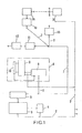
- 1 denotes the electrical connection to the usual 220 V network.
- the central controller 3 which is formed by a desktop computer with a terminal, is connected to the lines 2 leading to this connection.
- the values calculated by the central controller 3 can be printed out via the printer 4.
- the values determined by the central controller 3 are passed via the serial interface 5 via the four-wire bus line 7 to the controller 8 of the cylinder-piston unit 9, which is also connected to a displacement sensor 10.
- controller 8, cylinder-piston unit 9 and displacement sensor 10 are combined to form a unit, as indicated by 6.
- This unit 6 represents a closed control loop
- the other controllers 11, 12, 13, 14, 15-n are connected to the 220 V network via star and ring lines 7.
- the number of controllers 8, 11-n and thus the associated cylinder-piston units 9 is arbitrary and depends on the circumstances of the respective building.
- the central controller 3 transmits the target specifications for the individual cylinder-piston units 9 to their controllers 8, 11-n via the serial interface 5 in the form of a parallel serial converter with potential separation. Since these are coupled to a travel sensor 10, feedback is given to the associated controllers 8, 11-n and from these also to the central controller 3, so that a comparison can take place in the latter as to whether the specified travel path has actually been covered. If the acknowledgment signals from the individual controllers 8, 11-n do not arrive at the central controller 3, the lifting process is interrupted, since a fault must then exist.
- cylinder-piston units can be connected, in groups or individually, which can also be arranged in series or in parallel.
- Each unit 6 represents a self-contained control loop, with an additional forward and return line to the central controller 3. Its values can be made visible on a screen and printed out using a separate printer 4.
- a small electric pump 16 is connected to each cylinder-piston unit 9, the feed and return lines 17 of which are controlled by the associated computer 8 via electro-magnetic valves.
- the displacement sensor 10 is attached to the cylinder-piston unit 9 and is electrically connected to the associated controller 8.
- FIG. 3 The arrangement of a cylinder-piston unit 8 in the recess 18 of an inner wall of a cellar can be seen from FIG. 3, specifically covered by steel plates 19 at the top and bottom.
- the upper steel plate 19 lies flat below the basement cover 20, while the lower control plate 19 is placed on a concrete block 21 which is inserted into the niche 18.
Landscapes
- Engineering & Computer Science (AREA)
- Architecture (AREA)
- Structural Engineering (AREA)
- Civil Engineering (AREA)
- Chemical & Material Sciences (AREA)
- Chemical Kinetics & Catalysis (AREA)
- Electrochemistry (AREA)
- Mechanical Engineering (AREA)
- Life Sciences & Earth Sciences (AREA)
- General Life Sciences & Earth Sciences (AREA)
- Mining & Mineral Resources (AREA)
- Paleontology (AREA)
- General Engineering & Computer Science (AREA)
- Conveying And Assembling Of Building Elements In Situ (AREA)
- Actuator (AREA)
- Types And Forms Of Lifts (AREA)
- Forms Removed On Construction Sites Or Auxiliary Members Thereof (AREA)
Priority Applications (1)
| Application Number | Priority Date | Filing Date | Title |
|---|---|---|---|
| AT81104832T ATE18584T1 (de) | 1980-06-26 | 1981-06-23 | Verfahren und vorrichtung zum heben und/oder senken von gebaeuden oder -teilen, unter verwendung von hydraulischen zylinder-kolbeneinheiten, welche einzeln und/oder gruppenweise zusammengefasst steuerbar sind. |
Applications Claiming Priority (2)
| Application Number | Priority Date | Filing Date | Title |
|---|---|---|---|
| DE3023892 | 1980-06-26 | ||
| DE19803023892 DE3023892A1 (de) | 1980-06-26 | 1980-06-26 | Verfahren und vorrichtung zum heben und/oder senken von gebaeuden oder -teilen, unter verwendung von hydraulischen zylinder-kolben-einheiten, welche einzeln und/oder gruppenweise zusammengefasst steuerbar sind |
Publications (3)
| Publication Number | Publication Date |
|---|---|
| EP0043078A2 true EP0043078A2 (fr) | 1982-01-06 |
| EP0043078A3 EP0043078A3 (en) | 1982-06-23 |
| EP0043078B1 EP0043078B1 (fr) | 1986-03-12 |
Family
ID=6105488
Family Applications (1)
| Application Number | Title | Priority Date | Filing Date |
|---|---|---|---|
| EP81104832A Expired EP0043078B1 (fr) | 1980-06-26 | 1981-06-23 | Méthode et dispositif pour lever ou abaisser des bâtiments ou des parties de bâtiments en employant des unités de vérins hydrauliques qui sont commandées séparément ou en groupes |
Country Status (3)
| Country | Link |
|---|---|
| EP (1) | EP0043078B1 (fr) |
| AT (1) | ATE18584T1 (fr) |
| DE (1) | DE3023892A1 (fr) |
Cited By (9)
| Publication number | Priority date | Publication date | Assignee | Title |
|---|---|---|---|---|
| FR2547291A1 (fr) * | 1983-06-10 | 1984-12-14 | Epitoegepgyarto Vallalat | Dispositif de levage electro-hydraulique servant a soulever des plafonds |
| EP0404971A1 (fr) * | 1989-06-26 | 1991-01-02 | Bernfried Dr.-Ing. Sudbrack | Méthode et dispositif pour soulever, abaisser et/ou redresser un bâtiment |
| EP0457973A1 (fr) * | 1990-05-25 | 1991-11-27 | GERB Gesellschaft für Isolierung mbH & Co. KG | Méthode de mesurage de l'élévation et/ou de l'affaissement d'une construction ainsi que dispositions de mesurage pour la mise en application de la méthode |
| ES2067348A2 (es) * | 1991-12-04 | 1995-03-16 | Busquets Albert Busquets | Sistema integral de afianzamiento de vigas y forjados deteriorados en edificios, sus accesorios y forma de aplicacion. |
| FR2823521A1 (fr) * | 2001-04-13 | 2002-10-18 | Bouygues Batiment | Dispositif d'etaiement, etai, procede de mise en oeuvre d'un ensemble d'etais pour soutenir une charge et application au soutien d'un coffrage |
| RU2426837C1 (ru) * | 2010-03-05 | 2011-08-20 | Общество с ограниченной ответственностью "СТРОЙПЭН" (ООО "СтройПЭН") | Способ выравнивания монолитных железобетонных сооружений |
| RU2575193C1 (ru) * | 2014-12-29 | 2016-02-20 | Николай Васильевич Мальцев | Способ выравнивания здания, сооружения |
| RU2710741C1 (ru) * | 2019-04-26 | 2020-01-10 | Публичное акционерное общество "Татнефть" имени В.Д. Шашина | Способ выравнивания фундамента устьевых скважинных приводов и домкратный узел для его осуществления |
| CN116575788A (zh) * | 2023-05-30 | 2023-08-11 | 徐州中矿岩土技术股份有限公司 | 一种采动区倾斜铁塔纠偏装置 |
Families Citing this family (8)
| Publication number | Priority date | Publication date | Assignee | Title |
|---|---|---|---|---|
| DE3611753C2 (de) * | 1986-04-08 | 1993-12-16 | Bilfinger Berger Bau | Vorrichtung zum gleichmäßigen Heben und Senken sowie gleichmäßigen horizontalen Verschieben von Bauwerken |
| DE3802910A1 (de) * | 1988-02-01 | 1989-08-10 | Kunz Alfred & Co | Verfahren zum absenken von bauwerken |
| DD270955A1 (de) * | 1988-02-29 | 1989-08-16 | Warnke Umformtech Veb K | Justiereinrichtung fuer pressen zur automatischen kompensation von setzungen des fundamentes |
| DE3827004A1 (de) * | 1988-08-09 | 1990-02-15 | Gkn Keller Gmbh | Verfahren und vorrichtung zum ausgleich von senkungen der bebauung an der oberflaeche, vorzugsweise von gebaeudeschiefstellungen |
| DE4201667C2 (de) * | 1992-01-22 | 1995-06-01 | Kunz Alfred & Co | Verfahren zum Abstützen einer belasteten Stahlbetonpplatte |
| DE4238484C2 (de) * | 1992-11-14 | 1995-01-12 | Klaus Bau Gmbh | Verfahren und Vorrichtung zum Vergrößern des Höhenabstands eines Dachstuhls von der obersten Geschoßdecke eines Gebäudes |
| DE29507608U1 (de) * | 1995-05-11 | 1995-07-27 | Bilfinger + Berger Bauaktiengesellschaft, 68165 Mannheim | Vorrichtung zum Bewegen von Bauwerken |
| RU2225480C2 (ru) * | 2002-02-21 | 2004-03-10 | Пензенская государственная архитектурно-строительная академия | Фундамент для внецентренно нагруженной колонны |
Family Cites Families (5)
| Publication number | Priority date | Publication date | Assignee | Title |
|---|---|---|---|---|
| GB778913A (en) * | 1954-02-26 | 1957-07-17 | Pynford Ltd | Improvements in or relating to apparatus for levelling structures |
| GB839192A (en) * | 1955-05-10 | 1960-06-29 | Pynford Ltd | Improvements in or relating to electrical control arrangements |
| DE1215339B (de) * | 1964-04-25 | 1966-04-28 | Hochtief Ag Hoch Tiefbauten | Verfahren zum Anheben horizontal liegender Platten an Stuetzen bei der Herstellung von Hochbauten nach dem Hubplattenverfahren |
| GB1148496A (en) * | 1965-03-31 | 1969-04-10 | Costain Ltd Richard | Improvements relating to methods of constructing buildings and jacking systems for use therewith |
| FR1533321A (fr) * | 1967-06-05 | 1968-07-19 | Commissariat Energie Atomique | Procédé et dispositif de réajustement de la position relative d'un ensemble d'organes reliés individuellement au sol |
-
1980
- 1980-06-26 DE DE19803023892 patent/DE3023892A1/de not_active Withdrawn
-
1981
- 1981-06-23 EP EP81104832A patent/EP0043078B1/fr not_active Expired
- 1981-06-23 AT AT81104832T patent/ATE18584T1/de active
Cited By (9)
| Publication number | Priority date | Publication date | Assignee | Title |
|---|---|---|---|---|
| FR2547291A1 (fr) * | 1983-06-10 | 1984-12-14 | Epitoegepgyarto Vallalat | Dispositif de levage electro-hydraulique servant a soulever des plafonds |
| EP0404971A1 (fr) * | 1989-06-26 | 1991-01-02 | Bernfried Dr.-Ing. Sudbrack | Méthode et dispositif pour soulever, abaisser et/ou redresser un bâtiment |
| EP0457973A1 (fr) * | 1990-05-25 | 1991-11-27 | GERB Gesellschaft für Isolierung mbH & Co. KG | Méthode de mesurage de l'élévation et/ou de l'affaissement d'une construction ainsi que dispositions de mesurage pour la mise en application de la méthode |
| ES2067348A2 (es) * | 1991-12-04 | 1995-03-16 | Busquets Albert Busquets | Sistema integral de afianzamiento de vigas y forjados deteriorados en edificios, sus accesorios y forma de aplicacion. |
| FR2823521A1 (fr) * | 2001-04-13 | 2002-10-18 | Bouygues Batiment | Dispositif d'etaiement, etai, procede de mise en oeuvre d'un ensemble d'etais pour soutenir une charge et application au soutien d'un coffrage |
| RU2426837C1 (ru) * | 2010-03-05 | 2011-08-20 | Общество с ограниченной ответственностью "СТРОЙПЭН" (ООО "СтройПЭН") | Способ выравнивания монолитных железобетонных сооружений |
| RU2575193C1 (ru) * | 2014-12-29 | 2016-02-20 | Николай Васильевич Мальцев | Способ выравнивания здания, сооружения |
| RU2710741C1 (ru) * | 2019-04-26 | 2020-01-10 | Публичное акционерное общество "Татнефть" имени В.Д. Шашина | Способ выравнивания фундамента устьевых скважинных приводов и домкратный узел для его осуществления |
| CN116575788A (zh) * | 2023-05-30 | 2023-08-11 | 徐州中矿岩土技术股份有限公司 | 一种采动区倾斜铁塔纠偏装置 |
Also Published As
| Publication number | Publication date |
|---|---|
| ATE18584T1 (de) | 1986-03-15 |
| DE3023892A1 (de) | 1982-01-28 |
| EP0043078B1 (fr) | 1986-03-12 |
| EP0043078A3 (en) | 1982-06-23 |
Similar Documents
| Publication | Publication Date | Title |
|---|---|---|
| EP0043078A2 (fr) | Méthode et dispositif pour lever ou abaisser des bâtiments ou des parties de bâtiments en employant des unités de vérins hydrauliques qui sont commandées séparément ou en groupes | |
| DE102007030107B4 (de) | Verfahren und System zum elektrohydraulischen Ausrichten von Tragkörpern | |
| DE3515762A1 (de) | Mehrsaeulen-hebebuehe od. dgl. und verfahren zur gleichlaufsteuerung ihrer hubelemente | |
| DE2735554B2 (de) | Vorrichtung zum Testen hydraulischer Steuerungssysteme | |
| DE2611468C2 (de) | Verfahren zum Heben von Lasten sowie Vorrichtung zum Durchführen des Verfahrens | |
| DE1484577B1 (de) | Vorrichtung zum Eintreiben oder Ziehen von Pfaehlen,Spundbohlen od.dgl. | |
| DE2758291B2 (de) | Stapelwechselvorrichtung | |
| DE10063278C5 (de) | Vorrichtung zum Trennen von aneinander anhaftenden Lagen eines Porenbetonblocks | |
| DE102016214468A1 (de) | Brückenstützeinrichtung zum Abstützen eines Brückensegments und Verfahren zum Betrieb von Brückenstützeinrichtungen | |
| DE4238484A1 (de) | Verfahren und Vorrichtung zum Vergrößern des Höhenabstands eines Dachstuhls von der obersten Geschoßdecke eines Gebäudes | |
| DE2036601A1 (de) | Vorrichtung zur Lagerung von Bauwerken | |
| DE1534972A1 (de) | Verfahren zum seitlichen Fuehren von Decken beim Anheben derselben waehrend der Errichtung eines Gebaeudes | |
| EP0457973A1 (fr) | Méthode de mesurage de l'élévation et/ou de l'affaissement d'une construction ainsi que dispositions de mesurage pour la mise en application de la méthode | |
| CH667639A5 (de) | Elektrohydraulische hebevorrichtung. | |
| EP3231763B1 (fr) | Circuit de commande électrohydraulique pour un manipulateur de grande taille | |
| DE1925059C3 (de) | Verfahren zum Verbinden und Stapeln ineinandergefügter Isolierkörper zu einem Stutzisolator und Isolierkörper zur Anwendung des Verfahrens | |
| DE3403977A1 (de) | Verfahren zur hebung von baukoerpern mit schieflage in eine gewuenschte nullage | |
| EP1661843B1 (fr) | Méthode pour le déplacement de charges lourdes et accessoire d'aide au levage pour un appareil de levage | |
| DE2163880A1 (de) | Verfahren zum anheben und bewegen von bauwerken | |
| DE3423998C1 (de) | Verfahren zur Herstellung von Brückenüberbauten o.dgl. langen Bauwerken aus Stahl- oder Spannbeton mit Hilfe einer frei tragenden Vorschubrüstung und Vorrichtung zur Durchführung des Verfahrens | |
| DE10235858B4 (de) | Verfahren zum Erneuern und Sanieren von Fundamenten | |
| EP3255227A1 (fr) | Construction d'aide au montage et procédé de changement d'un élément de structure porteuse | |
| DE68912140T2 (de) | Automatische einstellvorrichtung in maschinen zum aufrichten von schachteln oder kartons. | |
| AT384453B (de) | Pressvorrichtung | |
| DE2331471C3 (de) | Aufgeständerter Fußboden o. dgl |
Legal Events
| Date | Code | Title | Description |
|---|---|---|---|
| PUAI | Public reference made under article 153(3) epc to a published international application that has entered the european phase |
Free format text: ORIGINAL CODE: 0009012 |
|
| AK | Designated contracting states |
Designated state(s): AT BE CH FR GB IT NL SE |
|
| PUAL | Search report despatched |
Free format text: ORIGINAL CODE: 0009013 |
|
| AK | Designated contracting states |
Designated state(s): AT BE CH FR GB IT NL SE |
|
| 17P | Request for examination filed |
Effective date: 19821029 |
|
| ITF | It: translation for a ep patent filed | ||
| RAP1 | Party data changed (applicant data changed or rights of an application transferred) |
Owner name: JUMOE GEBAEUDEHEBUNGSGESELLSCHAFT MBH |
|
| GRAA | (expected) grant |
Free format text: ORIGINAL CODE: 0009210 |
|
| AK | Designated contracting states |
Kind code of ref document: B1 Designated state(s): AT BE CH FR GB IT LI NL SE |
|
| REF | Corresponds to: |
Ref document number: 18584 Country of ref document: AT Date of ref document: 19860315 Kind code of ref document: T |
|
| PGFP | Annual fee paid to national office [announced via postgrant information from national office to epo] |
Ref country code: AT Payment date: 19860616 Year of fee payment: 6 |
|
| PGFP | Annual fee paid to national office [announced via postgrant information from national office to epo] |
Ref country code: NL Payment date: 19860630 Year of fee payment: 6 |
|
| ET | Fr: translation filed | ||
| PLBE | No opposition filed within time limit |
Free format text: ORIGINAL CODE: 0009261 |
|
| STAA | Information on the status of an ep patent application or granted ep patent |
Free format text: STATUS: NO OPPOSITION FILED WITHIN TIME LIMIT |
|
| 26N | No opposition filed | ||
| PG25 | Lapsed in a contracting state [announced via postgrant information from national office to epo] |
Ref country code: AT Effective date: 19870623 |
|
| PG25 | Lapsed in a contracting state [announced via postgrant information from national office to epo] |
Ref country code: SE Effective date: 19870624 |
|
| PG25 | Lapsed in a contracting state [announced via postgrant information from national office to epo] |
Ref country code: LI Effective date: 19870630 Ref country code: CH Effective date: 19870630 |
|
| BERE | Be: lapsed |
Owner name: JUMO GEBAUDEHEBUNGS G.M.B.H. Effective date: 19870630 |
|
| PG25 | Lapsed in a contracting state [announced via postgrant information from national office to epo] |
Ref country code: NL Effective date: 19880101 |
|
| NLV4 | Nl: lapsed or anulled due to non-payment of the annual fee | ||
| PG25 | Lapsed in a contracting state [announced via postgrant information from national office to epo] |
Ref country code: FR Free format text: LAPSE BECAUSE OF NON-PAYMENT OF DUE FEES Effective date: 19880226 |
|
| REG | Reference to a national code |
Ref country code: CH Ref legal event code: PL |
|
| GBPC | Gb: european patent ceased through non-payment of renewal fee | ||
| REG | Reference to a national code |
Ref country code: FR Ref legal event code: ST |
|
| PG25 | Lapsed in a contracting state [announced via postgrant information from national office to epo] |
Ref country code: GB Effective date: 19881118 |
|
| PG25 | Lapsed in a contracting state [announced via postgrant information from national office to epo] |
Ref country code: BE Effective date: 19890630 |
|
| EUG | Se: european patent has lapsed |
Ref document number: 81104832.1 Effective date: 19880711 |