EP0043328A1 - Anlage zur Energieerzeugung mit mehreren Kernreaktoren mit schnellen Neutronen und einer Einrichtung zum Be- und Entladen der Brennelemente - Google Patents
Anlage zur Energieerzeugung mit mehreren Kernreaktoren mit schnellen Neutronen und einer Einrichtung zum Be- und Entladen der Brennelemente Download PDFInfo
- Publication number
- EP0043328A1 EP0043328A1 EP81401046A EP81401046A EP0043328A1 EP 0043328 A1 EP0043328 A1 EP 0043328A1 EP 81401046 A EP81401046 A EP 81401046A EP 81401046 A EP81401046 A EP 81401046A EP 0043328 A1 EP0043328 A1 EP 0043328A1
- Authority
- EP
- European Patent Office
- Prior art keywords
- ramp
- reactor
- loading
- ramps
- enclosure
- Prior art date
- Legal status (The legal status is an assumption and is not a legal conclusion. Google has not performed a legal analysis and makes no representation as to the accuracy of the status listed.)
- Granted
Links
- 239000000446 fuel Substances 0.000 title claims abstract description 10
- 238000009434 installation Methods 0.000 title description 3
- 238000007599 discharging Methods 0.000 title 1
- 230000000712 assembly Effects 0.000 claims abstract description 37
- 238000000429 assembly Methods 0.000 claims abstract description 37
- 238000002955 isolation Methods 0.000 claims abstract description 22
- 238000004891 communication Methods 0.000 claims abstract description 14
- 230000005855 radiation Effects 0.000 claims description 9
- 230000001681 protective effect Effects 0.000 claims description 5
- 230000000284 resting effect Effects 0.000 claims description 2
- 239000002184 metal Substances 0.000 claims 2
- DGAQECJNVWCQMB-PUAWFVPOSA-M Ilexoside XXIX Chemical compound C[C@@H]1CC[C@@]2(CC[C@@]3(C(=CC[C@H]4[C@]3(CC[C@@H]5[C@@]4(CC[C@@H](C5(C)C)OS(=O)(=O)[O-])C)C)[C@@H]2[C@]1(C)O)C)C(=O)O[C@H]6[C@@H]([C@H]([C@@H]([C@H](O6)CO)O)O)O.[Na+] DGAQECJNVWCQMB-PUAWFVPOSA-M 0.000 abstract description 2
- 239000007788 liquid Substances 0.000 abstract description 2
- 229910052708 sodium Inorganic materials 0.000 abstract description 2
- 239000011734 sodium Substances 0.000 abstract description 2
- 238000006073 displacement reaction Methods 0.000 description 5
- 238000010276 construction Methods 0.000 description 4
- 238000005202 decontamination Methods 0.000 description 2
- 230000003588 decontaminative effect Effects 0.000 description 2
- 238000000605 extraction Methods 0.000 description 2
- 238000009413 insulation Methods 0.000 description 2
- 238000012423 maintenance Methods 0.000 description 2
- 210000000056 organ Anatomy 0.000 description 2
- 230000000295 complement effect Effects 0.000 description 1
- 230000008878 coupling Effects 0.000 description 1
- 238000010168 coupling process Methods 0.000 description 1
- 238000005859 coupling reaction Methods 0.000 description 1
- 230000008021 deposition Effects 0.000 description 1
- 230000000694 effects Effects 0.000 description 1
- 239000011810 insulating material Substances 0.000 description 1
- 230000007246 mechanism Effects 0.000 description 1
- 238000011176 pooling Methods 0.000 description 1
Images




Classifications
-
- G—PHYSICS
- G21—NUCLEAR PHYSICS; NUCLEAR ENGINEERING
- G21C—NUCLEAR REACTORS
- G21C19/00—Arrangements for treating, for handling, or for facilitating the handling of, fuel or other materials which are used within the reactor, e.g. within its pressure vessel
- G21C19/32—Apparatus for removing radioactive objects or materials from the reactor discharge area, e.g. to a storage place; Apparatus for handling radioactive objects or materials within a storage place or removing them therefrom
-
- G—PHYSICS
- G21—NUCLEAR PHYSICS; NUCLEAR ENGINEERING
- G21C—NUCLEAR REACTORS
- G21C19/00—Arrangements for treating, for handling, or for facilitating the handling of, fuel or other materials which are used within the reactor, e.g. within its pressure vessel
- G21C19/20—Arrangements for introducing objects into the pressure vessel; Arrangements for handling objects within the pressure vessel; Arrangements for removing objects from the pressure vessel
-
- Y—GENERAL TAGGING OF NEW TECHNOLOGICAL DEVELOPMENTS; GENERAL TAGGING OF CROSS-SECTIONAL TECHNOLOGIES SPANNING OVER SEVERAL SECTIONS OF THE IPC; TECHNICAL SUBJECTS COVERED BY FORMER USPC CROSS-REFERENCE ART COLLECTIONS [XRACs] AND DIGESTS
- Y02—TECHNOLOGIES OR APPLICATIONS FOR MITIGATION OR ADAPTATION AGAINST CLIMATE CHANGE
- Y02E—REDUCTION OF GREENHOUSE GAS [GHG] EMISSIONS, RELATED TO ENERGY GENERATION, TRANSMISSION OR DISTRIBUTION
- Y02E30/00—Energy generation of nuclear origin
- Y02E30/30—Nuclear fission reactors
Definitions
- the invention relates to a device for loading and unloading of fuel assemblies for a fast neutron nuclear reactor allowing the passage of the assemblies between a primary loading and unloading ramp communicating with the tank of a fast neutron reactor and a secondary ramp. communicating with an assembly storage or loading area.
- the fuel assemblies constituting the core of the nuclear reactor arranged in the vessel thereof must be able to be replaced after a certain period of use in the reactor.
- These extraction and transfer means generally comprise a transfer machine arranged above the reactor vessel allowing the extraction of the core assemblies, their transfer and their deposition in an area of the reactor vessel into which a ramp emerges. transport of assemblies called primary ramp.
- This primary ramp allows the transport of assemblies from the reactor vessel to a transfer device called loading and unloading lock in which the assembly can be transferred into a second ramp called secondary ramp which communicates with a storage area for assemblies or with a loading area for these assemblies in means of transport or temporary storage
- the assemblies are moved inside the primary and ⁇ - secondary ramps by traction devices such as winches.
- the loading and unloading lock contains a mobile ramp fixed to a turnstile allowing its rotation under the effect of motor means arranged at the top of the lock for its displacement by pivoting between a position where the mobile ramp is in the extension of the primary ramp and a position where this mobile ramp is located in the extension of the secondary ramp.
- the traction device is generally fixed on the turnstile and therefore follows the rotational movements of the mobile ramp.
- Some lock loading and unloading comprise two movable ramps whose simultaneous rotation allows to pass each of these ramps to a position in communication with the re primai- ramp to a position where it is in communication with the secondary ramp and Conversely.
- the loading and unloading airlock and the transfer devices associated with it are based on the reactor structure on which the vessel and the associated reactor installations are fixed.
- the periods of operation of this element are spaced in time as they correspond to periods during which it stops the reactor for reloading in combus- t i ble.
- the airlock is used not only for unloading irradiated assemblies but for reloading the reactor with new assemblies, the movement of these assemblies taking place from the storage area to the heart of the reactor via the secondary and primary ramps.
- the mechanical devices of the loading and unloading airlock are therefore brought to operate at extremely distant moments in time, so that one cannot be sure of the good functioning of these mechanical organs which have undergone a very long stop. duration.
- the object of the invention is therefore to propose a device for loading and unloading fuel assemblies for a nuclear reactor. with fast neutrons allowing the passage of assemblies between a primary loading and unloading ramp communicating with the tank of a fast neutron reactor and a secondary ramp communicating with an area for storing or loading assemblies, constituted by an airlock resting on the reactor structure, this one also carrying the primary and secondary ramps, inside which are fixed a transfer means constituted by au.
- this loading and unloading device should make it possible to reduce the cost of building nuclear reactors grouped on the same site while ensuring more frequent service of the mechanical elements of the device on any of the nuclear reactors located nearby. each other and while also allowing easy maintenance of the airlock during the operation of the reactor.
- the loading and unloading device is removable as a whole, the airlock being constituted by a demountable enclosure, transportable and comprising connection and isolation means, at the level of openings made in its wall, for its communication with the primary and secondary ramps of a reactor.
- FIG. 1 schematically represents the entire device for transferring an assembly between the reactor core and a storage and decontamination area for the assemblies, in the case of a nuclear reactor comprising an airlock for loading and unloading according to the prior art.
- FIG. 2 shows in a view in section through a vertical plane of symmetry a loading and unloading device according to the i n - vention in its operating position on a nuclear reactor.
- Figure 3 shows in a sectional view identical to the view of Figure 2 the same device uncoupled from the nuclear reactor.
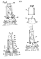
- Figure 4 shows in a sectional view identical to the views Figures 2 and 3, a second embodiment of a loading and unloading device according to the invention, in its uncoupled position relative to the nuclear reactor.
- FIG. 5 represents a loading and unloading device according to the invention, according to a third embodiment in a sectional view through a vertical plane of symmetry, the loading and unloading device being in its operating position on the reactor nuclear.
- Figure 6 shows, in a sectional view identical to the view of Figure 5, the device; shown in this figure in its uncoupled position relative to the nuclear reactor.
- FIG. 7 represents, in a sectional view through a plane of symmetry, a first embodiment of the means of connection and isolation of the airlock, in its position in service on the reactor.
- Figure 8 shows the means of connection and isolation of the airlock shown in Figure 7 in their uncoupled position relative to the nuclear reactor.
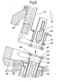
- Figure 9 shows in a sectional view a second embodiment of the means of connection and isolation of the airlock.
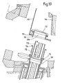
- FIG. 10 represents the means of connection and isolation of the airlock represented in FIG. 9 in their uncoupled position relative to the nuclear reactor.
- Figure 1 we see the structure 1 of a nuclear reactor carrying a tank 2 inside which are arranged assemblies 3 constituting the core of the nuclear reactor.
- a transfer machine 5 which can be moved in rotation to occupy any position above the network of fuel assemblies by means of rotary caps 7 and 8 ensures the transfer of the assemblies 3 first to position 3a by means of telescopic movements of the transfer machine then in position 3b by rotation of the transfer machine then lowering of the assembly vertically by telescopic movements.
- the assembly can be tilted in a ramp 10 called primary ramp which opens at its upper part in an airlock 11 inside which also a ramp 12 communicates the airlock with a storage area 14.
- the isolation of the airlock from ramps 10 and 12 can be carried out using valves 16 and 17.
- a ramp movable in rotation 15 secured to a turntable 18 disposed at the upper part of the airlock 11 can be placed successively in position 15a in communication with the primary ramp and in position 15b in communication with the secondary ramp.
- An assembly 3 can be brought inside this mobile ramp from the primary ramp or from the secondary ramp thanks to a winch 19 surmounting the airlock 11 called the loading and unloading airlock.
- the displacement of the assemblies inside the ramps 10 and 12 and inside the airlock can be carried out only by the winch 19 or by the winch 19 and other winches arranged at the entrance to the primary and secondary ramps.
- the assembly can be taken care of after tilting in the vertical position, by a transfer machine 20 which can move the assembly 3 in the vertical direction in one direction and in the other, which enables this assembly 3 to be placed in any position inside the rotating storage barrel 21 disposed inside the storage area 14.
- new assemblies arranged in the storage zone can be removed by the transfer machine 20 and deposited in the part of this zone which makes it possible to tilt them in the secondary ramp 12 for the introduction of these assemblies into the reactor vessel. through the loading and unloading airlock. 11.
- the loading and unloading lock is permanently arranged on the structure 1 of the nuclear reactor which carries the ramps 10 and 12 opening into the lock.
- the large airlock forms a complex and bulky assembly covered by the elements 23 of great thickness for the protection of the neighboring areas of the airlock against radiation.
- Such a device according to the invention comprises a sealed metallic enclosure 25 comprising two openings 26 and 27 corresponding respectively to the primary and secondary ramps 28 and 29 of the reactor on which the removable airlock according to the invention is placed.
- Valves 30 and 31 can close these openings 26 and 27 located on the enclosure . respectively while valves 32 and 33 allow the ends of the primary a: secondary ramps to be closed respectively, these ramps communicating with the interior of the reactor and the storage area.
- junction flanges arranged between the valves 30 and 32 and 31 and 33 respectively make it possible to fix the removable airlock constituted by the sealed enclosure 25 on the primary and secondary ramps of a nuclear reactor.
- the enclosure 25 is covered by elements 34 providing insulation against radiation from the outside of the airlock relative to the inside.
- a mobile ramp 35 is placed inside the airlock on a rotating element 36 which makes it possible to put this ramp in communication either with the primary ramp 28 or with the secondary ramp 29.
- a winch 37 which allows the movement of the fuel assemblies inside the ramps either in the direction of the ascent or in the direction of the descent.
- FIG. 3 it can be seen that when the uncoupling between the removable airlock and the reactor has been carried out by dismantling the assembly flange disposed between the isolation valves, the removable airlock can be raised by an overhead crane, gripping elements 38 being provided at the upper part of the airlock.
- FIG 4 there is shown a removable airlock identical to the airlock shown in Figures 2 and 3 but whose insulation elements against radiation are made up of two separate parts 41 and 42 which can be put in place on the enclosure 25 or on the contrary separated from it independently of one another.
- the whole of the airlock and its radiation insulating elements is of very great weight, for example 400 to 500 tonnes and it may be difficult to have sufficient lifting means to lift the whole airlock above the reactor and to move it to a new service position above another reactor.
- FIGS. 5 and 6 another embodiment of the enclosure of the removable airlock has been shown, this enclosure 45 being constituted by a cylinder comprising two openings 46 and 47 at its lower part and an assembly 48 for moving the mobile ramp 50 and a winch 49 at its upper part.
- this assembly can be disconnected from the primary and secondary ramps of the reactor and extracted from the protective structure 51 constituted by a very thick cylinder of insulating material placed at a fixed position on the reactor and whose the right section corresponds to the right section of the enclosure.
- a complementary protective plate 52 is then placed on the upper part of the cylinder 51 to completely isolate the interior of the reactor.
- FIGS 7 and 8 show in more detail all of the means of connection and isolation of the airlock and the secondary ramp of the reactor.
- connection and isolation means are placed at the level of the openings of the enclosure 55 allowing the latter to be placed in communication with the primary ramp or with the secondary ramp.
- FIGS. 7 and 8 show the connection and isolation devices allowing the enclosure to be placed in communication with the secondary ramp 56 secured to the structure 57 of the reactor.
- the ramp 56 is integral with an assembly comprising an isolation valve 58 and a fixing flange 59 carrying centering pins 60.
- the enclosure 55 carries at its lower part, by means of a bellows seal 61, an isolation valve 62 and a section of ramp 63 fixed relative to the enclosure 55, apart from slight displacements or deflections of this ramp 63 relative to the enclosure 55, obtained by deformation of the bellows seal 61 placed in the extension of the ramp 56.
- the mobile ramp 64 can then be placed in the prolon management of the ramp 63 by tilting.
- the ramp 64 has been shown in its position where it is in communication with the secondary ramp 56 and in FIG. 8, the mobile ramp 64 has been shown in a position where the mobile ramp and the fixed ramp are not more in line with each other.
- the mobile ramp is movable by tilting and rotation between its position shown in FIG. 7 and a position where the mobile ramp 64 is in the extension of a section of fixed ramp not shown allowing the junction with the primary ramp of the reactor.
- the enclosure 55 is surrounded by radiation protection elements 65 which come during the installation of the airlock on the reactor in the extension of protection elements 66 integral with the structure 57 of the reactor, to constitute with these ci protection on: out the perimeter of the airlock.
- a flange 67 is on the other hand secured to the valve 62 at its lower end coming into position opposite the flange 59 secured to the valve 58 disposed on the fixed structure supporting the secondary ramp on the reactor.
- the flange 67 has holes allowing the centering pins 60 to be put in place when the airlock is approaching the reactor.
- the removable airlock according to the invention having to be used on several reactors, for example arranged on the same site, it is necessary to be able to adapt the junction device of this airlock to slight dimensional differences which may exist between two reactors as regards L ' tilt or position of the primary and secondary ramps. This is the reason why the ramp 63 secured to the enclosure 55 is fixed to: it by means of a bellows seal 61 which allows slight displacements or deflections.
- the centering pins 60 of the flange 59 can always be made to coincide with the holes in the flange 67.
- the airlock is fixed by tightening the flanges 59 and 67 and the corresponding flanges at the primary ramp.
- the ramps 59 and 67 comprise a certain number of holes 68 in which screws are introduced which are fixed by nuts.
- a slight angular variation in the displacement of the mobile ramp makes it possible to absorb slight deviations coming from deviations between the inclinations or the centers of the ramps from one reactor to another.
- FIGS. 9 and 10 another embodiment of the junction and isolation device between the enclosure 55 and the secondary ramp 56 is seen, the enclosure 55 carrying at its opening 69 a flange 70 carrying pins centering 71.
- the upper end of the ramp 56 carries a valve 72 itself extended by a portion of the ramp 73, however a flange 74 having holes corresponding to the centering pins 71 is fixed to the valve 72 by means of a bellows seal 75.
- An internal valve 77 enables the opening 69 to be closed when the airlock is isolated from the external environment for its transport, for example.
- the main advantages of the device according to the invention are that it makes it possible to use only one airlock containing the mobile devices for loading and unloading assemblies for a set of reactors, which saves on costs. construction of the nuclear reactor, to operate the mechanisms associated with the airlock more frequently and to allow easy maintenance of the airlock during the operation of the reactor.
- the shape of the enclosure constituting the airlock is not limited to the forms which have been described and shown, that the mode of fixing and isolation of the airlock can be different from the modes of fixing and isolation. which have been described and that the achievement of radiation protection can be obtained in a different way from the modes individuals described.
- the loading and unloading device can be used for all fast neutron nuclear reactors using an airlock passing the fuel elements from a primary rail communicating with the reactor vessel to a secondary rail communicating with a point for storing or loading fuel assemblies.
Landscapes
- Physics & Mathematics (AREA)
- Engineering & Computer Science (AREA)
- Plasma & Fusion (AREA)
- General Engineering & Computer Science (AREA)
- High Energy & Nuclear Physics (AREA)
- Carriers, Traveling Bodies, And Overhead Traveling Cranes (AREA)
- Monitoring And Testing Of Nuclear Reactors (AREA)
Applications Claiming Priority (2)
| Application Number | Priority Date | Filing Date | Title |
|---|---|---|---|
| FR8014637A FR2486297A1 (fr) | 1980-07-01 | 1980-07-01 | Dispositif de chargement et de dechargement d'assemblages combustibles pour reacteur nucleaire a neutrons rapides |
| FR8014637 | 1980-07-01 |
Publications (2)
| Publication Number | Publication Date |
|---|---|
| EP0043328A1 true EP0043328A1 (de) | 1982-01-06 |
| EP0043328B1 EP0043328B1 (de) | 1984-09-26 |
Family
ID=9243719
Family Applications (1)
| Application Number | Title | Priority Date | Filing Date |
|---|---|---|---|
| EP81401046A Expired EP0043328B1 (de) | 1980-07-01 | 1981-06-30 | Anlage zur Energieerzeugung mit mehreren Kernreaktoren mit schnellen Neutronen und einer Einrichtung zum Be- und Entladen der Brennelemente |
Country Status (4)
| Country | Link |
|---|---|
| US (1) | US4443403A (de) |
| EP (1) | EP0043328B1 (de) |
| DE (1) | DE3166316D1 (de) |
| FR (1) | FR2486297A1 (de) |
Families Citing this family (4)
| Publication number | Priority date | Publication date | Assignee | Title |
|---|---|---|---|---|
| US4737336A (en) * | 1986-04-04 | 1988-04-12 | The United States Of America As Represented By The United States Department Of Energy | Core assembly storage structure |
| FR2599542B1 (fr) * | 1986-05-29 | 1988-08-05 | Commissariat Energie Atomique | Installation de manutention des assemblages constituant le coeur d'un reacteur nucleaire a neutrons rapides |
| JP5675448B2 (ja) * | 2011-03-11 | 2015-02-25 | 三菱重工業株式会社 | 燃料棒交換装置 |
| IT202300017415A1 (it) | 2023-08-21 | 2025-02-21 | Newcleo S R L | Sistema e procedimento di movimentazione di gruppi combustibile |
Citations (7)
| Publication number | Priority date | Publication date | Assignee | Title |
|---|---|---|---|---|
| FR1525102A (fr) * | 1967-01-26 | 1968-05-17 | Commissariat Energie Atomique | Dispositif de chargement et de déchargement en combustible pour réacteur nucléaire |
| FR1527225A (fr) * | 1967-04-21 | 1968-05-31 | Commissariat Energie Atomique | Installation de chargement et de déchargement en combustible pour réacteur nucléaire |
| FR2188251A1 (de) * | 1972-06-08 | 1974-01-18 | Commissariat Energie Atomique | |
| FR2192057A1 (de) * | 1972-07-10 | 1974-02-08 | Commissariat Energie Atomique | |
| FR2267614A1 (en) * | 1974-04-11 | 1975-11-07 | Commissariat Energie Atomique | Articulated handling machines - which protect fast reactor containment vessel have links and release system to separate top and bottom portions of machine |
| FR2279201A1 (fr) * | 1974-06-10 | 1976-02-13 | Commissariat Energie Atomique | Dispositif de protection du dome de l'enceinte de confinement d'un reacteur nucleaire |
| FR2368122A1 (fr) * | 1976-10-15 | 1978-05-12 | Commissariat Energie Atomique | Dispositif de chargement et dechargement en combustible pour reacteur nucleaire |
Family Cites Families (4)
| Publication number | Priority date | Publication date | Assignee | Title |
|---|---|---|---|---|
| CH529425A (de) * | 1971-03-25 | 1972-10-15 | Bbc Brown Boveri & Cie | Brennelement-Wechselmaschine |
| GB1488075A (en) * | 1974-04-11 | 1977-10-05 | Commissariat Energie Atomique | Arrangement for protecting the containment vessel dome of a nuclear reactor |
| JPS5241792A (en) * | 1975-09-29 | 1977-03-31 | Fuji Electric Co Ltd | Fuel transfer device of atomic reactor |
| FR2464539A1 (fr) * | 1979-08-30 | 1981-03-06 | Commissariat Energie Atomique | Ensemble de traversee de dalle de confinement pour transfert de combustible nucleaire irradie |
-
1980
- 1980-07-01 FR FR8014637A patent/FR2486297A1/fr active Granted
-
1981
- 1981-06-10 US US06/272,430 patent/US4443403A/en not_active Expired - Fee Related
- 1981-06-30 DE DE8181401046T patent/DE3166316D1/de not_active Expired
- 1981-06-30 EP EP81401046A patent/EP0043328B1/de not_active Expired
Patent Citations (7)
| Publication number | Priority date | Publication date | Assignee | Title |
|---|---|---|---|---|
| FR1525102A (fr) * | 1967-01-26 | 1968-05-17 | Commissariat Energie Atomique | Dispositif de chargement et de déchargement en combustible pour réacteur nucléaire |
| FR1527225A (fr) * | 1967-04-21 | 1968-05-31 | Commissariat Energie Atomique | Installation de chargement et de déchargement en combustible pour réacteur nucléaire |
| FR2188251A1 (de) * | 1972-06-08 | 1974-01-18 | Commissariat Energie Atomique | |
| FR2192057A1 (de) * | 1972-07-10 | 1974-02-08 | Commissariat Energie Atomique | |
| FR2267614A1 (en) * | 1974-04-11 | 1975-11-07 | Commissariat Energie Atomique | Articulated handling machines - which protect fast reactor containment vessel have links and release system to separate top and bottom portions of machine |
| FR2279201A1 (fr) * | 1974-06-10 | 1976-02-13 | Commissariat Energie Atomique | Dispositif de protection du dome de l'enceinte de confinement d'un reacteur nucleaire |
| FR2368122A1 (fr) * | 1976-10-15 | 1978-05-12 | Commissariat Energie Atomique | Dispositif de chargement et dechargement en combustible pour reacteur nucleaire |
Non-Patent Citations (1)
| Title |
|---|
| ENERGIE NUCLEAIRE,vol. 13, no. 3, 1971 Paris, FR E. BENOIST et al.: "La centrale Phénix", pages 196-205. * |
Also Published As
| Publication number | Publication date |
|---|---|
| US4443403A (en) | 1984-04-17 |
| DE3166316D1 (en) | 1984-10-31 |
| FR2486297B1 (de) | 1985-01-04 |
| EP0043328B1 (de) | 1984-09-26 |
| FR2486297A1 (fr) | 1982-01-08 |
Similar Documents
| Publication | Publication Date | Title |
|---|---|---|
| EP2617040B1 (de) | Vorrichtung zur trockenhandhabung von kernbrennstabbündeln | |
| CA2729320C (fr) | Dispositif de mesure de grandeurs physiques de matieres nucleaires et procede de mise en oeuvre d'un tel dispositif | |
| EP0202958A1 (de) | Transport-, Positionierungs- und Verbindungsanordnung eines Behälters unter dem Ladeschacht einer Kerninstallation | |
| EP0043328B1 (de) | Anlage zur Energieerzeugung mit mehreren Kernreaktoren mit schnellen Neutronen und einer Einrichtung zum Be- und Entladen der Brennelemente | |
| EP2092533B1 (de) | Kernbrennstoff-transporteinrichtung und verfahren zum beladen/entladen der einrichtung | |
| FR2558006A1 (fr) | Dispositif pour la manutention d'assemblages de combustible nucleaire et assemblage adapte a un tel dispositif | |
| EP0048671B1 (de) | Anlage zur Energieerzeugung mit mehreren Kernreaktoren mit schnellen Neutronen und mit einer Vorrichtung zum Auswechseln von Brennelementen | |
| EP0020487A1 (de) | Kernanlage und Verfahren zu seiner Herstellung. | |
| FR2953319A1 (fr) | Dispositif et procede d'assistance au chargement et dechargement du coeur d'un reacteur nucleaire a caloporteur sodium et reacteur nucleaire a caloporteur sodium comprenant un tel dispositif | |
| FR2788628A1 (fr) | Dispositif et procede de chargement du coeur d'un reacteur nucleaire | |
| EP0681302A1 (de) | Maschine zum Beladen von Brennstabbündeln der Spaltzone eines Kernreaktors mit abnehmbaren Leitträgern | |
| WO2005045849A2 (fr) | Dispositif et procede de conditionnement d'assemblages de combustible nucleaire a double barriere de confinement. | |
| EP0044246A2 (de) | Bestrahlungsanlage mit einer Vorrichtung zum Einbringen und Positionieren zum Bestrahlen von Targets | |
| FR2605787A1 (fr) | Installation de manutention du combustible dans un reacteur nucleaire a neutrons rapides | |
| FR2582438A1 (fr) | Hotte de manutention et de transport d'assemblages de combustible nucleaire et installation comportant une hotte de ce type | |
| FR2914483A1 (fr) | Dispositif de manutention des equipements d'un reacteur nucleaire. | |
| EP2628160B1 (de) | Vorrichtung zur vorübergehenden Stützung der oberen inneren Teile auf einem Gefäss eines Druckwasserreaktors | |
| FR2583205A1 (fr) | Machine pour demonter des reacteurs nucleaires declasses ou leurs composants | |
| EP0247937B1 (de) | Ladeeinrichtung für spaltzonenbildende Elemente eines Kernreaktors mit schnellen Neutronen | |
| EP0150148B1 (de) | Kernreaktor mit schnellen Neutronen, der mit einem zentralen Wartungsraum und einem aus Maschinenräumen bestehenden Verschlussteil versehen ist | |
| BE1008006A3 (fr) | Procede et dispositif de retournement d'un assemblage combustible d'un reacteur nucleaire refroidi a l'eau. | |
| FR2486295A1 (fr) | Coeur de reacteur nucleaire d'axe vertical, notamment pour reacteur du type refroidi par un metal liquide | |
| EP0218485B1 (de) | Handhabungseinrichtung zum Einführen und Herausziehen einer Apparatur durch eine Öffnung in einem dichten Gehäuse | |
| FR2719698A1 (fr) | Machine de chargement d'assemblages combustibles du cÓoeur d'un réacteur nucléaire comportant des moyens de guidage et de déplacement amovibles. | |
| FR2475784A1 (fr) | Dispositif de transfert et de stockage d'assemblages combustibles pour reacteurs nucleaires |
Legal Events
| Date | Code | Title | Description |
|---|---|---|---|
| PUAI | Public reference made under article 153(3) epc to a published international application that has entered the european phase |
Free format text: ORIGINAL CODE: 0009012 |
|
| 17P | Request for examination filed |
Effective date: 19810915 |
|
| AK | Designated contracting states |
Designated state(s): BE DE FR GB IT LU NL |
|
| ITF | It: translation for a ep patent filed | ||
| GRAA | (expected) grant |
Free format text: ORIGINAL CODE: 0009210 |
|
| AK | Designated contracting states |
Designated state(s): BE DE FR GB IT LU NL |
|
| REF | Corresponds to: |
Ref document number: 3166316 Country of ref document: DE Date of ref document: 19841031 |
|
| PG25 | Lapsed in a contracting state [announced via postgrant information from national office to epo] |
Ref country code: LU Free format text: LAPSE BECAUSE OF NON-PAYMENT OF DUE FEES Effective date: 19850630 |
|
| PLBE | No opposition filed within time limit |
Free format text: ORIGINAL CODE: 0009261 |
|
| STAA | Information on the status of an ep patent application or granted ep patent |
Free format text: STATUS: NO OPPOSITION FILED WITHIN TIME LIMIT |
|
| 26N | No opposition filed | ||
| PGFP | Annual fee paid to national office [announced via postgrant information from national office to epo] |
Ref country code: LU Payment date: 19890530 Year of fee payment: 9 |
|
| PGFP | Annual fee paid to national office [announced via postgrant information from national office to epo] |
Ref country code: BE Payment date: 19900531 Year of fee payment: 10 |
|
| PGFP | Annual fee paid to national office [announced via postgrant information from national office to epo] |
Ref country code: DE Payment date: 19900606 Year of fee payment: 10 |
|
| PGFP | Annual fee paid to national office [announced via postgrant information from national office to epo] |
Ref country code: GB Payment date: 19900619 Year of fee payment: 10 Ref country code: FR Payment date: 19900619 Year of fee payment: 10 |
|
| ITTA | It: last paid annual fee | ||
| PGFP | Annual fee paid to national office [announced via postgrant information from national office to epo] |
Ref country code: NL Payment date: 19900630 Year of fee payment: 10 |
|
| PG25 | Lapsed in a contracting state [announced via postgrant information from national office to epo] |
Ref country code: GB Effective date: 19910630 Ref country code: BE Effective date: 19910630 |
|
| BERE | Be: lapsed |
Owner name: NOVATOME Effective date: 19910630 |
|
| PG25 | Lapsed in a contracting state [announced via postgrant information from national office to epo] |
Ref country code: NL Effective date: 19920101 |
|
| NLV4 | Nl: lapsed or anulled due to non-payment of the annual fee | ||
| GBPC | Gb: european patent ceased through non-payment of renewal fee | ||
| PG25 | Lapsed in a contracting state [announced via postgrant information from national office to epo] |
Ref country code: FR Effective date: 19920228 |
|
| REG | Reference to a national code |
Ref country code: FR Ref legal event code: ST |
|
| PG25 | Lapsed in a contracting state [announced via postgrant information from national office to epo] |
Ref country code: DE Effective date: 19920602 |