EP0218485B1 - Handhabungseinrichtung zum Einführen und Herausziehen einer Apparatur durch eine Öffnung in einem dichten Gehäuse - Google Patents
Handhabungseinrichtung zum Einführen und Herausziehen einer Apparatur durch eine Öffnung in einem dichten Gehäuse Download PDFInfo
- Publication number
- EP0218485B1 EP0218485B1 EP86401326A EP86401326A EP0218485B1 EP 0218485 B1 EP0218485 B1 EP 0218485B1 EP 86401326 A EP86401326 A EP 86401326A EP 86401326 A EP86401326 A EP 86401326A EP 0218485 B1 EP0218485 B1 EP 0218485B1
- Authority
- EP
- European Patent Office
- Prior art keywords
- piston
- tube
- passage
- plug
- periscope
- Prior art date
- Legal status (The legal status is an assumption and is not a legal conclusion. Google has not performed a legal analysis and makes no representation as to the accuracy of the status listed.)
- Expired
Links
- 238000007789 sealing Methods 0.000 claims description 9
- 230000000712 assembly Effects 0.000 claims description 6
- 238000000429 assembly Methods 0.000 claims description 6
- 239000000446 fuel Substances 0.000 claims description 4
- 230000005855 radiation Effects 0.000 claims description 4
- 230000037431 insertion Effects 0.000 claims 2
- 238000003780 insertion Methods 0.000 claims 2
- DGAQECJNVWCQMB-PUAWFVPOSA-M Ilexoside XXIX Chemical compound C[C@@H]1CC[C@@]2(CC[C@@]3(C(=CC[C@H]4[C@]3(CC[C@@H]5[C@@]4(CC[C@@H](C5(C)C)OS(=O)(=O)[O-])C)C)[C@@H]2[C@]1(C)O)C)C(=O)O[C@H]6[C@@H]([C@H]([C@@H]([C@H](O6)CO)O)O)O.[Na+] DGAQECJNVWCQMB-PUAWFVPOSA-M 0.000 description 5
- 238000000605 extraction Methods 0.000 description 5
- 238000009434 installation Methods 0.000 description 5
- 229910052708 sodium Inorganic materials 0.000 description 5
- 239000011734 sodium Substances 0.000 description 5
- 239000007788 liquid Substances 0.000 description 4
- 230000000284 resting effect Effects 0.000 description 4
- XKRFYHLGVUSROY-UHFFFAOYSA-N Argon Chemical compound [Ar] XKRFYHLGVUSROY-UHFFFAOYSA-N 0.000 description 2
- 235000021183 entrée Nutrition 0.000 description 2
- 239000007789 gas Substances 0.000 description 2
- 230000007935 neutral effect Effects 0.000 description 2
- 238000000926 separation method Methods 0.000 description 2
- 238000012800 visualization Methods 0.000 description 2
- 102000000591 Tight Junction Proteins Human genes 0.000 description 1
- 108010002321 Tight Junction Proteins Proteins 0.000 description 1
- 229910052786 argon Inorganic materials 0.000 description 1
- 230000000903 blocking effect Effects 0.000 description 1
- 210000004027 cell Anatomy 0.000 description 1
- 210000000078 claw Anatomy 0.000 description 1
- 230000008878 coupling Effects 0.000 description 1
- 238000010168 coupling process Methods 0.000 description 1
- 238000005859 coupling reaction Methods 0.000 description 1
- 238000006073 displacement reaction Methods 0.000 description 1
- 239000003517 fume Substances 0.000 description 1
- 239000011261 inert gas Substances 0.000 description 1
- 150000002500 ions Chemical class 0.000 description 1
- 238000002955 isolation Methods 0.000 description 1
- 238000005272 metallurgy Methods 0.000 description 1
- 238000005086 pumping Methods 0.000 description 1
- 230000002285 radioactive effect Effects 0.000 description 1
- 238000011084 recovery Methods 0.000 description 1
- 210000000352 storage cell Anatomy 0.000 description 1
- 239000000126 substance Substances 0.000 description 1
- 210000001578 tight junction Anatomy 0.000 description 1
- 231100000331 toxic Toxicity 0.000 description 1
- 230000002588 toxic effect Effects 0.000 description 1
Images


Classifications
-
- G—PHYSICS
- G21—NUCLEAR PHYSICS; NUCLEAR ENGINEERING
- G21C—NUCLEAR REACTORS
- G21C17/00—Monitoring; Testing ; Maintaining
- G21C17/08—Structural combination of reactor core or moderator structure with viewing means, e.g. with television camera, periscope, window
-
- Y—GENERAL TAGGING OF NEW TECHNOLOGICAL DEVELOPMENTS; GENERAL TAGGING OF CROSS-SECTIONAL TECHNOLOGIES SPANNING OVER SEVERAL SECTIONS OF THE IPC; TECHNICAL SUBJECTS COVERED BY FORMER USPC CROSS-REFERENCE ART COLLECTIONS [XRACs] AND DIGESTS
- Y02—TECHNOLOGIES OR APPLICATIONS FOR MITIGATION OR ADAPTATION AGAINST CLIMATE CHANGE
- Y02E—REDUCTION OF GREENHOUSE GAS [GHG] EMISSIONS, RELATED TO ENERGY GENERATION, TRANSMISSION OR DISTRIBUTION
- Y02E30/00—Energy generation of nuclear origin
- Y02E30/30—Nuclear fission reactors
Definitions
- the invention relates to a handling device for introducing and extracting equipment through an orifice of a sealed enclosure, using conventional handling means such as a winch and maintaining, during all phases of handling, a seal. satisfactory enclosure.
- Fast neutron nuclear reactors generally include a large tank containing the reactor core immersed in liquid sodium.
- the reactor vessel is closed at its upper part by a very thick concrete slab ensuring the biological protection of the reactor area located above the vessel and the sealed closure of this vessel.
- the liquid sodium in which the reactor core dips fills the tank to a certain level, the space between this upper level of the sodium and the slab being filled with an inert gas such as argon.
- the slab is pierced with openings allowing the sealed passage of various components and carries a set of rotating plugs themselves supporting a transfer machine placed vertically from the core, to carry out the handling of the fuel assemblies of the core, during the operations of reloading this heart.
- equipment such as control equipment
- the passageways passing through the slab, these plugs or the upper part of the loading machine, reserved for control equipment, must be sealed as well when the equipment is in place in the reactor. nuclear power only during the operating phases of the reactor where the control devices are not used.
- the bushing passages are closed by plugs - and include locking and sealing means allowing a tight fixing of the plug in the bushing passage.
- the closure plugs are indeed, obviously removable, and must be able to be disassembled and replaced during the introduction or extraction of the corresponding apparatus.
- hoods provided with a system of valves acting as a lock for the handling operations.
- FR-A-1 475 913 also discloses a device for supporting a lighting lamp in a sealed enclosure inside which radioactive products are handled.
- the lamp can be placed in the enclosure by means of an assembly comprising a piston mounted mobile and sealed in a cylinder passing through the wall of the enclosure.
- Such a device mounted inside the wall of the enclosure could not be used for the introduction or extraction of very long equipment such as display equipment, in an orifice of a sealed enclosure, the closure is ensured by a plug.
- the object of the invention is therefore to propose a handling device for introducing and extracting an apparatus through an orifice of a sealed enclosure
- a conventional handling means such as a winch associated with an introduction assembly intended for cooperate with a cylindrical passage passing through the wall of the enclosure at the level of the orifice, which is closed by a cylindrical plug cooperating with a means of sealing the cylindrical passage which is operable to open the orifice
- the device comprising in addition, a piston mounted movable and sealed inside a cylinder for carrying out the introduction and extraction of the apparatus, this device of simple structure, inexpensive and compact, making it possible to carry out handling operations through the wall of the sealed enclosure in a simple and rapid manner and without requiring other means of handling or lifting than those usually associated with the operation of an installation. industrial ion.
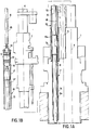
- Figs. 1a and 1b are sectional views through a vertical plane of the handling device in the service position on the slab of the nuclear reactor.
- Fig. 1a relates to the lower part of the handling device.
- Fig. 1 relates to the upper part of the handling device.
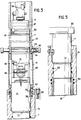
- Fig. 2 is a sectional view through a vertical plane of a plug closing a passage for crossing the slab of the nuclear reactor.
- Fig. 2a is a view along A of FIG. 2.
- Fig. 3 is a sectional view through a vertical plane of a part of the handling device comprising the piston and its connecting members.
- Figs. 4a, 4b, 4c, 4d, 4e and 4f are schematic views showing the progress of a handling operation making it possible to introduce a periscope for observing the heads of assemblies, in a fast neutron nuclear reactor.
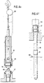
- Fig. 5 is a sectional view of the upper part of the periscope in the service position in the nuclear reactor vessel.
- Figs. 1a and 1b we see the loading machine 1 of a fast neutron nuclear reactor which is mounted to move in rotation about a vertical axis on the small rotating plug 2 of the nuclear reactor itself rotatably mounted around a vertical axis on the large rotating plug resting on the reactor slab.
- the axes of rotation of the large rotary cap, the small rotary cap and the loading machine are different vertical axes, so that the vertical arm of the transfer machine is offset from the axis of rotation of this transfer machine can be placed vertically from any position of core assemblies, by choosing the angular positions of the large rotating plug, the small rotating plug and the transfer machine.
- FIG. 1a There is therefore shown in FIG. 1a, the axis 4 of the transfer arm and the axis of rotation 5 of the 'transfer machine 1.
- the handling device according to the invention is mounted on the transfer machine, along a third vertical axis 6 substantially symmetrical with the axis 4 of the transfer arm relative to the axis of rotation 5 of the transfer machine 1.
- the crossing machine comprises a vertical cylindrical passage 7 constituted by a crossing tube 7a and by an upper assembly and sealing sleeve 7b.
- the cylindrical passage 7 constitutes a well making the interior volume of the reactor communicate below the slab 2, with the exterior above this slab.
- the passage 7 is normally closed by a plug 8 which will be described in more detail with reference to FIG. 2.
- the upper cuff 7b makes it possible to fix in a sealed manner as will be explained in more detail with reference to FIG. 3, the lower part 10a of the tube of the handling device.
- the tube 10 has an inner diameter greater than the current diameter of the passage 7.
- the main elements of the handling device can be seen in their position corresponding to the positioning of the device before the introduction of a display means into the reactor enclosure.
- the tube 10 has been placed in position on the cuff 7b at the end of the passage 7 and connected to this cuff in a sealed manner.
- the tube 10 contains, from top to bottom, a piston 11 and the display device 13 constituted by a very long periscope, comprising an internal biological protection means making it possible to stop the radiation from the reactor.
- the piston 11 is mounted mobile in the direction of the axis 6, in a sealed manner, inside the tube 10, by means of sealing segments 12.
- the piston 11 has at its upper end, a connecting means 14 consisting of a yoke which can be connected with a horizontal hinge pin to the lower part of a connecting rod 15, the upper part of which is connected to the handling bridge of the nuclear reactor.
- the lower part 16 of the piston 11 constitutes a connecting yoke with a horizontal axis of the piston with the upper part 17 of the periscope 13.
- the periscope 13 comprises a running part constituted by a cylindrical envelope whose diameter is less than the inside diameter of the tube 10 and which has an opening 18 at its lower part constituting the periscope observation window.
- the upper part 17 of the periscope constituting the piston connecting yoke 11 has a diameter greater than the diameter of the current part, this diameter however being substantially less than the inside diameter of the tube 10.
- This part 17 is connected to the current part of the tube of the periscope via a frustoconical bearing surface, as described with reference to FIG. 5.
- the envelope of the periscope 13 has a careful part 13 ' sely calibrated and rectified intended to cooperate with the seals 20 to seal in the passage 7.
- the lower part of the tubular casing of the periscope 13 constitutes a removable connection means to the upper part of the plug 8.
- the inner surface of the tube 10 carefully calibrated and rectified constitutes a chamber similar to a jack chamber for guiding the sealed piston 11 during its movements in the direction of the axis 6.
- the assembly constituted by the rod 15, the piston 11, the periscope 13 and the plug 8 can be moved in the direction of the axis 6, in a perfectly guided manner, thanks to the bridge of the nuclear reactor or thanks to a hoist suspended above the transfer machine 1.
- the upper part of the through passage 7 of the transfer machine 1 is seen, enclosing the closure plug 8 and closed at its upper part by a closure bell 19 tightly fixed on the cuff 7b constituting the upper part of the passage 7.
- the plug 8 comprises a tubular lower part 8a of which only the upper part has been shown in FIG. 2 and an upper part in several parts ensuring the fixing and sealing of the plug 8 inside the cuff 7b.
- the lower part 8a of the plug as can be seen in FIG. 1a, has a length greater than the thickness of the slab 2 allowing it to occupy the entire length of the passage 7 from the lower surface of the slab 2 to the upper cuff 7b fixed on the transfer machine 1.
- the cuff 7b is fixed to the transfer machine 1 by means of screws 21 and includes seals 22 and 23 making it possible to make a tight junction with the tubular part 7a of the passage 7 and with the transfer machine respectively.
- the cuff 7b also includes a set of seals 20 making it possible to seal between the head of the plug 8 ′ and the passage 7.
- the plug 8 thus makes it possible to seal the passage 7 at its upper part and d '' avoid convection currents in this passage.
- the plug 8 also contains, in its part corresponding to the crossing of the slab 2 of the reactor, metallic masses fixed on an axial direction rod ensuring the closure of the plug at its lower part and allowing the constitution of a screen to ensure the biological protection vertical to the passage well of the display device.
- the upper part of the plug 8 comprises the means making it possible to keep it inside the cuff 7b of the passage 7.
- These means comprise a piston 25 mounted axially movable and in rotation inside the upper part of the plug 8.
- the piston is returned to the high position oar a spring 26 resting on a ball stop 27.
- the piston 25 is integral with a finger 29 whose end is engaged with a light 30 passing through the envelope of the plug and the shape of which is visible in FIG. 2a.
- the piston 25 In the position shown in Figs. 2 and 2a, the piston 25 is held in a position such that it pushes outward a set of support balls 32 resting on a conical bearing surface of the cuff 7b of the passage 7.
- the finger 29 can be passed from its position 29a shown in FIG. 2a in position 29b, thus allowing the piston to move upwards under the action of the spring 26 and to release the balls 32 which can then retract towards the inside of the plug.
- the plug is then no longer locked inside the cuff 7b and can then be moved down inside the passage 7.
- the plug 8 also has an external assembly profile 33 making it possible to connect it to the lower part of the handling device constituted by the base of the periscope 13. In FIG. 2, the plug 8 is shown in the position it occupies in all the phases where the display device is not used, for example during the operation of the nuclear reactor. A closing bell 19 is then fixed on the upper part of the cuff 7b.
- Fig. 3 the upper part of the cuff 7b and certain elements of the handling device are shown, the periscope 13 being introduced inside the passage 7 towards the inside of the reactor vessel.
- the tube 10 has at its lower part two openings 40 which can be closed by a sliding sleeve 41 provided with displacement and hooking means 42 and coming in the sealed closure position, as shown in FIG. 3 by means of seals 43 and 44 carried by the lower part of the tube 10 on either side of the openings 40.
- the tube 10 also has hooking grooves of the means 42, in the positions 45 and 45 'corresponding respectively to closing and opening the base of the tube 10.
- the articulated connecting means 14 and 16 of the piston 11 each have a horizontal assembly and articulation axis which can be removed or replaced by an operating handle and fixed in position by a pin.
- the axis 46 of the lower connecting piece 16 can be removed or replaced from the outside, when the closing sleeve 41 is in its upper position, these retaining means 42 being in position in the upper groove 45 '. It is thus possible to uncouple or re-couple the piston 11 and the head 17 of the periscope 13.
- the periscope When the periscope is placed as shown in FIG. 3, it can be separated from the piston 11 then dismantle the base of the tube 10 and the separate from the cuff 7b thanks to the handling bridge of the nuclear reactor.
- the periscope 13 in its service position, as shown in FIG. 5, then rests on the frustoconical bearing surface of the balls of the plug, by means of its frustoconical part separating the head 17 from the body of the periscope.
- a television camera 50 above the head 17 of the periscope to collect the images of the assembly heads captured by the periscope 13 whose lower window 18 is then at the level of the upper part of the reactor core.
- the periscope 13 is used when the nuclear reactor is shut down, the top of the core comprising the assembly heads being emerged above the liquid sodium, the level of which has been lowered to carry out the handling of the assemblies.
- Figs. 4a, 4b, 4c, 4d, 4e and 4f we will now refer to Figs. 4a, 4b, 4c, 4d, 4e and 4f, to describe a complete operation of placing the periscope in the nuclear reactor vessel, to ensure the control of assembly handling during the reloading of the core.
- Fig. 4a the plug 8 for closing the well 7 can be seen in the sealed closure position inside the cuff 7b, as shown in FIG. 2.
- the upper part of the plug 8 is capped by the closure and sealing bell 19.
- the handling device according to the invention is brought vertically to the well 7 thanks to the bridge of the nuclear reactor, the upper part of the tube 10 being connected by means of a stirrup 52 to a sling 51 fixed to the hook of the overhead crane.
- the tube 10 and the stirrup 52 are assembled by means of a pin 53 passing through two diametrically opposite holes passing through the wall of the tube 10 and into an opening 47 visible in FIG. 3 passing through the upper connecting piece 14 of the piston 11. In this way the piston 11 is locked at the same time in the high position inside the tube 10.
- Fig. 4b we see the tube 10 whose sheath 41 is in the open position and the periscope 13 in their relative position, just before the fixing of the lower end of the periscope 13 on the plug 8.
- the attachment pole 54 has been connected to the connecting piece 14 of the piston 11 and the caliper 52 has been dismantled, so that the piston 11 is unlocked and it is suspended as well as the periscope 13 from the actuating pole 54 itself connected to the hoist '56.
- the periscope 13 is lowered onto the upper end of the plug 8; the lower end of the periscope 13, has an internal profile corresponding to the profile 33 of the plug 8 coming to ensure the junction of the handling device with the plug, by a combined movement in translation and in rotation shown diagrammatically by the arrows 58.
- the periscope 13 and the plug 8 are then assembled by a claw or bayonet system ensuring their junction.
- the plug 8 is then unlocked, as shown in FIG. 4c, by a combined movement of translation and rotation of the periscope 13 secured to the head of the plug 8. This movement makes it possible to return the blocking piston 25 of the balls 32 to the high position, the plug thus being unlocked. It can be seen that then the assembly of the piston 11, of the periscope 13 and of the plug 8 is suspended from the actuating pole 54 fixed to the hoist 56. It may be noted that.
- the plug can only be unlocked when the coupling the end of the periscope 13 on the plug head has been produced, the subsequent unlocking maneuver being carried out by means of the periscope connected to the head of the plug 8.
- the sheath 41 and the entire device are then closed handling is in the position as shown in FIG.
- FIGS. 1 a and 1b which also corresponds to the position shown in FIGS. 1 a and 1b.
- the tube 10 is first swept with neutral gas (that of the reactor), then the piston and the periscope 13 are lowered until the head of the periscope comes to bear on the frustoconical surface of the cuff 7b, as shown in FIG. 3.
- the piston 11 is then in its lowest position and the lower part of the periscope comprising the observation window 18 is then at the level of the assembly heads of the nuclear reactor core.
- the sleeve 41 mounted on the lower part 35 of the tube 10 is then raised in the open position, which gives access to the axis 46 of connection between the part 16 of the piston and the part 17 of the periscope and separate the piston from the periscope.
- the connection between the base 35 of the tube 10 and the cuff 7b is also eliminated.
- using the hoist 56 separate the assembly constituted by the piston 11 and the tube 10 in which the piston 11 moves, from the head of the periscope.
- FIG. 4f There is shown in FIG. 4f, the periscope 13 in the service position in the nuclear reactor.
- the observation window 18 is at the level of the assembly heads and the plug 8 is fixed to the lower end of the periscope 13 partially dipped in liquid sodium, the level 60 of which has been lowered to leave the assembly heads emerging .
- the television camera 50 is fixed on the head 17 of the periscope 13 which can then provide the visualization of the fuel handling operations.
- the periscope then provides, through the upper part 13 ′ of its external envelope, the diameter of which is identical to the diameter of the plug 8, the tight closure of the well 7 thanks to the seal 20.
- the periscope 13 also provides biological protection thanks to an internal device stopping the radiation from the reactor.
- the periscope can be extracted from the nuclear reactor vessel by the reverse operations to those which have been described. During all these operations, as well as during the introduction of the periscope, the seal is always maintained either by the periscope, or by the piston 11, or finally by the plug replaced. During these operations, the plug is also locked when it is replaced. This locking can only be achieved before the separation of the periscope and the stopper, so that the stopper cannot fall back into the tank since it is either held by the handling device or locked on the cuff 7b.
- the handling device makes it possible to set up and recover an observation device such as a periscope in the tank of a fast neutron nuclear reactor by constantly maintaining a tight closure of this tank and operating under very good security conditions.
- the handling device is also very simple and does not require the use of watertight hoods fitted with valves and a specific lifting device. During all the handling operations, the operators performing the hoist operation and the separation or fixing of the elements of the handling device are perfectly protected against radiation or against gaseous fumes from the tank. In addition, the volume of air to be swept and filled with neutral gas is very low.
- the invention is not limited to the embodiment which has been described. This is how we can imagine other means of connecting the various elements of the handling device and other lifting means for moving these elements.
- the handling device according to the invention can be used for the installation and recovery of any equipment in different sealed enclosures of a nuclear reactor.
- the handling device can be used for the installation and recovery of any equipment in different sealed enclosures of a nuclear reactor.
Landscapes
- Physics & Mathematics (AREA)
- Engineering & Computer Science (AREA)
- Plasma & Fusion (AREA)
- General Engineering & Computer Science (AREA)
- High Energy & Nuclear Physics (AREA)
- Monitoring And Testing Of Nuclear Reactors (AREA)
Claims (5)
Applications Claiming Priority (2)
| Application Number | Priority Date | Filing Date | Title |
|---|---|---|---|
| FR8510673 | 1985-07-11 | ||
| FR8510673A FR2584851B1 (fr) | 1985-07-11 | 1985-07-11 | Dispositif tubulaire d'introduction et d'extraction d'un appareillage a travers un orifice d'une enceinte etanche |
Publications (2)
| Publication Number | Publication Date |
|---|---|
| EP0218485A1 EP0218485A1 (de) | 1987-04-15 |
| EP0218485B1 true EP0218485B1 (de) | 1989-09-20 |
Family
ID=9321220
Family Applications (1)
| Application Number | Title | Priority Date | Filing Date |
|---|---|---|---|
| EP86401326A Expired EP0218485B1 (de) | 1985-07-11 | 1986-06-17 | Handhabungseinrichtung zum Einführen und Herausziehen einer Apparatur durch eine Öffnung in einem dichten Gehäuse |
Country Status (3)
| Country | Link |
|---|---|
| EP (1) | EP0218485B1 (de) |
| DE (1) | DE3665789D1 (de) |
| FR (1) | FR2584851B1 (de) |
Family Cites Families (3)
| Publication number | Priority date | Publication date | Assignee | Title |
|---|---|---|---|---|
| FR1475913A (fr) * | 1966-02-23 | 1967-04-07 | Commissariat Energie Atomique | Dispositif support de lampe d'éclairage à l'intérieur d'une enceinte étanche |
| DE1964496A1 (de) * | 1969-12-23 | 1971-07-01 | Siemens Ag | Unterwasser-Endoskop |
| US4650634A (en) * | 1983-11-21 | 1987-03-17 | Westinghouse Electric Corp. | Quick release cushioned T.V. camera mount |
-
1985
- 1985-07-11 FR FR8510673A patent/FR2584851B1/fr not_active Expired
-
1986
- 1986-06-17 EP EP86401326A patent/EP0218485B1/de not_active Expired
- 1986-06-17 DE DE8686401326T patent/DE3665789D1/de not_active Expired
Also Published As
| Publication number | Publication date |
|---|---|
| FR2584851A1 (fr) | 1987-01-16 |
| DE3665789D1 (en) | 1989-10-26 |
| FR2584851B1 (fr) | 1987-11-27 |
| EP0218485A1 (de) | 1987-04-15 |
Similar Documents
| Publication | Publication Date | Title |
|---|---|---|
| EP0360629B1 (de) | Instrumentierungsvorrichtung für die Spaltzone eines Druckwasserkernreaktors und Verfahren und Vorrichtung zum Aus- und Einbau dieser Instrumentierungsvorrichtung | |
| BE897468A (fr) | Procede de remplacement des broches de guidage d'un tube-guide et dispositif correspondant | |
| EP2741298B1 (de) | System zum Greifen und Verriegeln / Entriegeln | |
| EP3227658B1 (de) | Verfahren und vorrichtung zum entziehen einer probe aus einer flüssigkeit | |
| EP0185561B1 (de) | Reinigungsvorrichtung der Führungsrohre von Neutronenflussmesseinrichtungen in einem Druckwasserkernreaktor | |
| EP1974357B1 (de) | Verfahren und einrichtung zum schliessen eines beladenen behälters mit bestrahltem kernbrennstoff in einem wassergefüllten pool | |
| WO2005034217A9 (fr) | Procede et dispositif de conditionnement de crayons de combustible nucleaire non etanches en vue de leur transport et de leur stockage ou entreposage de longue duree | |
| FR2638843A1 (fr) | Dispositif d'echantillonnage d'un processus chimique | |
| EP2092533B1 (de) | Kernbrennstoff-transporteinrichtung und verfahren zum beladen/entladen der einrichtung | |
| EP0218485B1 (de) | Handhabungseinrichtung zum Einführen und Herausziehen einer Apparatur durch eine Öffnung in einem dichten Gehäuse | |
| EP0348250B1 (de) | Vorrichtung zum Öffnen und Schliessen eines Filters in einer Kernanlage und Verfahren zum Auswechseln in einer Filtergarnitur | |
| EP0148802A2 (de) | Einrichtung zur Handhabung von Brennstoffelementen und Brennstoffelement für die Vorrichtung | |
| EP0238767B1 (de) | Zusammenbau eines abnehmbaren und verriegelbaren Führungsringes mit einem Platte und seine Anwendung für ein Führungsrohr eines Kernreaktors | |
| CA1057538A (fr) | Methode de soudure de conduites immergees par manchon telescopique et dispositif de mise en oeuvre | |
| BE1008007A3 (fr) | Procede et dispositif de detection de fuite sur un element combustible d'un assemblage pour reacteur nucleaire. | |
| FR2486702A1 (fr) | Installation pour irradiation munie de moyens perfectionnes pour le positionnement des cibles | |
| EP0389330A1 (de) | Pfropfen zum Abdichten einer Gewindebohrung und Werkzeug und Verfahren zum Einsetzen | |
| FR2722324A1 (fr) | Dispositif de pose et d'extraction d'un manchon de blocage d'un tube-guide dans un embout demontable d'un assemblage combustible de reacteur nucleaire | |
| FR2605787A1 (fr) | Installation de manutention du combustible dans un reacteur nucleaire a neutrons rapides | |
| FR1465775A (fr) | Dispositif de manutention, notamment pour un réacteur nucléaire | |
| EP0073723A1 (de) | Vorrichtung zur Lokalisierung von Bruchstellen in Hüllen von Brennelementen eines schnellen Brüters | |
| CH507570A (fr) | Bras de manutention | |
| EP0011005B1 (de) | Probenahmekopf für Kühlmittel eines Kernreaktors | |
| EP0110784A1 (de) | Verfahren und Vorrichtung für das Anschliessen einer Zweigleitung | |
| FR2676140A1 (fr) | Dispositif d'insertion d'une capsule d'irradiation dans un panier solidaire des equipements internes d'un reacteur nucleaire. |
Legal Events
| Date | Code | Title | Description |
|---|---|---|---|
| PUAI | Public reference made under article 153(3) epc to a published international application that has entered the european phase |
Free format text: ORIGINAL CODE: 0009012 |
|
| 17P | Request for examination filed |
Effective date: 19861018 |
|
| AK | Designated contracting states |
Kind code of ref document: A1 Designated state(s): BE DE GB IT NL |
|
| 17Q | First examination report despatched |
Effective date: 19880627 |
|
| GRAA | (expected) grant |
Free format text: ORIGINAL CODE: 0009210 |
|
| AK | Designated contracting states |
Kind code of ref document: B1 Designated state(s): BE DE GB IT NL |
|
| ITF | It: translation for a ep patent filed | ||
| REF | Corresponds to: |
Ref document number: 3665789 Country of ref document: DE Date of ref document: 19891026 |
|
| GBT | Gb: translation of ep patent filed (gb section 77(6)(a)/1977) | ||
| PLBE | No opposition filed within time limit |
Free format text: ORIGINAL CODE: 0009261 |
|
| STAA | Information on the status of an ep patent application or granted ep patent |
Free format text: STATUS: NO OPPOSITION FILED WITHIN TIME LIMIT |
|
| 26N | No opposition filed | ||
| ITPR | It: changes in ownership of a european patent |
Owner name: FUSIONI;FRAMATOME |
|
| PGFP | Annual fee paid to national office [announced via postgrant information from national office to epo] |
Ref country code: BE Payment date: 19910626 Year of fee payment: 6 |
|
| PGFP | Annual fee paid to national office [announced via postgrant information from national office to epo] |
Ref country code: NL Payment date: 19910630 Year of fee payment: 6 |
|
| NLS | Nl: assignments of ep-patents |
Owner name: FRAMATOME TE COURBEVOIE, FRANKRIJK. |
|
| REG | Reference to a national code |
Ref country code: GB Ref legal event code: 732 |
|
| PG25 | Lapsed in a contracting state [announced via postgrant information from national office to epo] |
Ref country code: BE Effective date: 19920630 |
|
| BERE | Be: lapsed |
Owner name: FRAMATOME Effective date: 19920630 |
|
| PG25 | Lapsed in a contracting state [announced via postgrant information from national office to epo] |
Ref country code: NL Effective date: 19930101 |
|
| NLV4 | Nl: lapsed or anulled due to non-payment of the annual fee | ||
| PGFP | Annual fee paid to national office [announced via postgrant information from national office to epo] |
Ref country code: DE Payment date: 19930527 Year of fee payment: 8 |
|
| PGFP | Annual fee paid to national office [announced via postgrant information from national office to epo] |
Ref country code: GB Payment date: 19930611 Year of fee payment: 8 |
|
| ITTA | It: last paid annual fee | ||
| PG25 | Lapsed in a contracting state [announced via postgrant information from national office to epo] |
Ref country code: GB Effective date: 19940617 |
|
| GBPC | Gb: european patent ceased through non-payment of renewal fee |
Effective date: 19940617 |
|
| PG25 | Lapsed in a contracting state [announced via postgrant information from national office to epo] |
Ref country code: DE Effective date: 19950301 |
|
| PG25 | Lapsed in a contracting state [announced via postgrant information from national office to epo] |
Ref country code: IT Free format text: LAPSE BECAUSE OF NON-PAYMENT OF DUE FEES;WARNING: LAPSES OF ITALIAN PATENTS WITH EFFECTIVE DATE BEFORE 2007 MAY HAVE OCCURRED AT ANY TIME BEFORE 2007. THE CORRECT EFFECTIVE DATE MAY BE DIFFERENT FROM THE ONE RECORDED. Effective date: 20050617 |