EP0043393A1 - Drahtknotmaschine - Google Patents
Drahtknotmaschine Download PDFInfo
- Publication number
- EP0043393A1 EP0043393A1 EP80302198A EP80302198A EP0043393A1 EP 0043393 A1 EP0043393 A1 EP 0043393A1 EP 80302198 A EP80302198 A EP 80302198A EP 80302198 A EP80302198 A EP 80302198A EP 0043393 A1 EP0043393 A1 EP 0043393A1
- Authority
- EP
- European Patent Office
- Prior art keywords
- wire
- driver
- end portion
- anvil
- knot
- Prior art date
- Legal status (The legal status is an assumption and is not a legal conclusion. Google has not performed a legal analysis and makes no representation as to the accuracy of the status listed.)
- Granted
Links
- 230000015572 biosynthetic process Effects 0.000 claims description 11
- 238000005452 bending Methods 0.000 claims description 4
- 238000004519 manufacturing process Methods 0.000 abstract description 9
- 238000003825 pressing Methods 0.000 abstract description 2
- 230000006378 damage Effects 0.000 description 4
- 208000027418 Wounds and injury Diseases 0.000 description 3
- 239000004744 fabric Substances 0.000 description 3
- 208000014674 injury Diseases 0.000 description 3
- 238000000034 method Methods 0.000 description 2
- 230000001360 synchronised effect Effects 0.000 description 2
- 229910000639 Spring steel Inorganic materials 0.000 description 1
- 238000010276 construction Methods 0.000 description 1
- 239000000463 material Substances 0.000 description 1
Images


Classifications
-
- B—PERFORMING OPERATIONS; TRANSPORTING
- B21—MECHANICAL METAL-WORKING WITHOUT ESSENTIALLY REMOVING MATERIAL; PUNCHING METAL
- B21F—WORKING OR PROCESSING OF METAL WIRE
- B21F15/00—Connecting wire to wire or other metallic material or objects; Connecting parts by means of wire
- B21F15/02—Connecting wire to wire or other metallic material or objects; Connecting parts by means of wire wire with wire
- B21F15/04—Connecting wire to wire or other metallic material or objects; Connecting parts by means of wire wire with wire without additional connecting elements or material, e.g. by twisting
-
- B—PERFORMING OPERATIONS; TRANSPORTING
- B21—MECHANICAL METAL-WORKING WITHOUT ESSENTIALLY REMOVING MATERIAL; PUNCHING METAL
- B21F—WORKING OR PROCESSING OF METAL WIRE
- B21F27/00—Making wire network, i.e. wire nets
- B21F27/12—Making special types or portions of network by methods or means specially adapted therefor
Definitions
- This invention relates to new and useful improvements in wire knotting machines, and has particular reference to a machine adapted to twist the end portion of a first wire first about a second wire disposed at right angles to the first, and then to twist the projecting end portion of the first wire about its own standing portion to form a secure connection between the wires.
- This connection although commonly denoted in the trade as a "knot", is not a knot in the technical sense that a strand is led through a loop or bight formed in itself.
- Flat grid springs commonly consist of a pair of parallel longitudinal spring side wires, with a continuous series of closely spaced apart spring cross wires extending laterally between and knotted at their ends about said side wires, and are commonly formed by automatic machinery in which the side wires are longitudinally advanced with an intermittent motion, the cross wires being advanced longitudinally and successively into position at a given station, cut to proper length, and knotted about the side wires while the side wires are at rest.
- the primary object of the present invention is the provision of a wire knotting machine capable of forming a knot of the type described with a single set of dies, and with a single motion of a driver member, whereby to form both the first and second twists in a time no greater than has heretofore been required for the formation of only the first twist.
- this object is accomplished by the provision of a driver which engages the end portion of a cross wire and turns it around the side wire to form the first twist, and by imposing a fixed anvil in the path of the cross wire end, said anvil being configurated to guide the cross wire end around its own standing portion, whereby the-second twist is formed during the final portion of the formation of the first twist. An approximate doubling of the production rate of the machine is thus permitted.
- the machine as thus far described provides a knot the second twist of which, that is, the bend of the cross wire end about its own standing portion, is spaced apart from the side wire, and in which the raw end of the cross wire projects away from the cross wire in an exposed position.
- This condition is permissable in some cases, such as when the resultant grid spring is to be completely enclosed, but in some cases, such as when the spring is to be exposed in use, the raw wire ends could inflict injury, snag upholstery fabrics, and the like.
- another object of the invention is the provision of means whereby each knot may be "finished” by pressing the second bend of the cross wire, and its raw end, into close proximity to the side wire, whereby the raw end is shielded.
- This finishing operation when its use is desired, is performed at a station in the movement of the side wires subsequent to that at which the knots are initially formed, so that it can occur, with respect to the knots of one cross wire, at the same time the knots of the next subsequent wire are being initially formed. In this manner, the finishing operation does not reduce the production rate of the machine.
- the grid spring to be formed comprises a wire fabric including a pair of parallel side wires 2 (one shown) and a series of closely spaced apart parallel cross wires 4 extending transversely between said side wires and knotted at their ends about said side wires by the machine forming the subject matter of the present invention, which is indicated generally by the numeral 6 in Figure 1.
- Side wires 2 are usually each provided with a sheath 8 (see Figure 6) of twisted paper or other soft, indentable material, and are often referred to as "ropes" because of their resemblance thereto.
- Both the side wires and the cross wires are formed of spring steel, the side wires being relatively heavy and the cross wires being relatively light.
- the grid is illustrated as being formed in a horizontal plane.
- the side wires are transported longitudinally and concurrently to the left as viewed in Figure 1, in the direction of arrow 10, which will be termed the "forward" direction. They are advanced with an intermittent motion, the distance between stops being equal to the desired spacing between successive cross wires 4, by any suitable mechanism, not shown as forming no intrinsic part of the present invention, but well understood in the art.
- the knotting machine shown is for forming the knots at the right side wire 2, as viewed when facing forwardly, and it will be understood that the knots at the left side wire are formed by a similar but reversed machine.
- wire for cross wires 4 may be fed from a reel source, not shown, through a tubular guide 12 carried by a bracket 14 affixed to machine frame 16, by any suitable means, not shown.
- the wire emerges from guide 12 at a distance outside of side wire 2 such as to provide a wire length outside of the side wire sufficient to form the knot, then passes transversely just below said side wire, then through a guide 18 which starts in inwardly spaced relation from right side wire 2 and extends to a similar relation to the left side wire, to extend outwardly beneath the left side wire at least as far as guide 12 is spaced outwardly, from the right side wire.
- guide 18 consists of a fixed portion 20 and a vertically movable portion 22, the portions normally cooperating to form a tunnel 24 through which wire 4 may be advanced.
- Movable portion 22 may be elevated upwardly as indicated by arrow 26 in Figure 10, whereby the holder is opened and wire 4 may exit transversely forwardly from the holder, as indicated by arrow 28, as will appear.
- Movable guide portion 22 is lifted by a rod 30 (see Figure 2) at the proper times, as will appear.
- a wire cutter blade 32 is actuated to sever the wire at the end of guide 12, the normal position of the blade being shown in Figures 2 and 4, and its position, when actuated being shown in Figure 3.
- the portion of the cross wire outside of the side wire will be denoted its "end portion” 4A, and the portion thereof between the side wires will be denoted its "standing portion” 4B.
- a driver member 34 constituting a tubular shaft which is horizontal and extends forwardly and rearwardly at right angles to wire 4, and through the central bore of which side wire 2 is advanced to pass just above cross wire 4.
- the rearward portion of the driver is carried rotatably in a carrier 36, which in turn is mounted for forward and rearward sliding movement in machine frame 16, as by a sliding dovetail connection 38.
- Carrier 36 is biased forwardly by a frame- based spring 40 (see Figure 1) to urge a transverse pin 42 thereof against a lever 44.
- Said lever is carried pivotally by machine frame 16, and is pivotally driven with a reciprocal motion to cooperate with spring 40 to move carrier 36 and driver 34 between a forward position in which the forward end of the driver substantially touches cross wire 4, and a rearward position in which the forward end of the driver is spaced rearwardly of wire 4 by a distance slightly greater than the diameter of the cross wire.
- Driver 34 is turned oscilla- tably by a pinion gear 46 ( Figure 1) fixed on its rearward end, which is engaged by a gear segment 48 carried by an oscillatable arm 50 which it will be understood is pivoted on machine frame 16, and driven by means to be described, to oscillate the driver through less than a full revolution.
- driver 34 is provided with a forward extension 52, projecting approximately the diameter of wire 4, and being eccentric to the driver axis and normally projecting forwardly beneath wire 4, as in Figure 1.
- driver 34 is turned in the direction of arrow 54 in Figures 2 - 5, by operation of gear members 46-48, just after wire 4 has been severed by blade 32 as in Figure 3.
- its extension 52 first engages end portion 4A of wire 4, and bends it around side wire 2, as indicated at 53, till it overlies standing portion 4B of wire 4, as in Figure 4.
- said driver is also retracted rearwardly against spring 40 by lever 44, so that by the time the Figure 4 position is reached, the free end portion 4A of the wire will be disposed just behind standing portion 4B, as best shown in Figure 8.
- driver extension 52 is undercut as indicated at 56 in Figure 1, and wire end 4A rests in the undercut, to insure that it does not slip out of engagement with the extension during the turning and rearward retraction of the driver.
- wire end 4A which projects outwardly from driver extension 52, is lead downwardly behind standing wire portion 4B, and then formed to bend forwardly and upwardly under wire portion 4B by an anvil 58.
- Anvil 58 has the form of an upwardly projecting finger, the upper end of which is at about at the level of side wire 2, and is upwardly concave, as at 60, about an axis of curvature at right angles to the side wire. Said concavity extends from about the plane of the forward end of the driver, forwardly beneath standing portion 4B of the wire. Thus as wire end 4A is pressed forcibly downwardly against the anvil, it is forced to bend forwardly beneath wire section 4B, as best shown in Figure 9 to form a hook bend 62 engaged below wire 4B.
- bracket 64 is connected to a bracket 64 by a bolt 66 in a manner to permit vertical adjustment of the anvil
- the bracket 64 is affixed to a second bracket 68 by a bolt 70 in a manner to permit adjustment of the anvil transversely to side wire 2, so that the anvil may be accurately adjusted depending on the wire diameter and resilience, as well as other variable factors.
- bracket 68 is affixed to machine frame 16.
- the means for intermittently advancing side wires 2, the means for advancing cross wires 4 into position, the means for actuating wire knife 32, the means for operating driver rotating gears 46-48, the means for operating driver retractor lever 44, and the means for operating lifter 30 to open and close guide 18, are all accurately synchronized in order that all of the described operations occur at the proper moments. This may be done, for example, by driving all of the enumerated devices from cams on a common cam shaft, so that slight adjustments of the cams will properly synchronize all functions. This is considered to be well within the known scope of the art.
- anvil 58 which provides that both the bend 53 of the cross wire about the side wire, and also the formation of hook 62, are accomplished in a single motion of driver 34, provides a production rate of about 300 cross wires per minute. This is an extremely important feature from the viewpoint of production economy.
- the knot formed as thus far described, and as shown in Figure 6, is a complete knot and provides a product which is entirely satisfactory for many purposes, such for example as when the product spring grid is to be totally enclosed in an eventual upholstery structure.
- a knot of this form does leave the cut raw ends of the cross wires projecting and exposed, so that they could snag anything they contact, thus doing damage or inflicting injury, and thus would be objectionable in certain other uses, such for example as when the spring grid, either bare or plastic-coated, is to be exposed and used to support free cushions or the like.
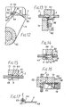
- an optional knot “finisher” may be used, and is shown in Figures 11 - 17.
- the finisher comprises a pair of cooperating die members consisting of an anvil finger 72 and a radial arm 74.
- Anvil finger 72 extends transversely to side wire 2, at the level thereof, forwardly of the position at which a cross wire 4 is being knotted about said side wire, by a distance equal to the desired spacing between successive cross wires.
- Said anvil finger overlies the side wire at its inner end portion, and is affixed at its outer end, by a screw 76, to a bracket 78 which it will be understood is affixed to machine frame 16.
- Said anvil is provided at its lower side with a notch 80 through which side wire 2 may advance longitudinally.
- Said notch provides a rounded corner 82 which when the side wire is engaged therein, braces said wire against upward or outward movement.
- the notch is enlarged at its forward end to present a forwardly facing shoulder 84, intermediate its forward and rearward end, which enlargement accommodates the bend 53 of the just previously knotted cross wire 4 about the side wire, with shoulder 84 then bracing the bend of wire 4 against rearward movement.
- the side wire must be deflected downwardly, and for this purpose the lower rearward portion of the portion of anvil finger 72 inwardly of said notch is bevelled downwardly and forwardly at its lower rearward portion as indicated at 86, and as best shown in Figures 13 and 14.
- cross wire 4 immediately adjacent the side wire engages said bevel, and is deflected downwardly, together with the side wire, until just as the side wire comes to rest, it snaps upwardly to engage the knot in the enlarged portion of notch 80, as wire 4 snaps up in front of a forwardly facing shoulder 88 of the anvil.
- crank 96 At the rearward end of said shaft, there is affixed thereto a crank 96 by means of which arm 74 may be angularly oscillated, being turned in one direction by said crank, and returned in the opposite direction by a torsion spring 98 surrounding shaft 92, being anchored at one end in one of bearings 94, and at its opposite end in the hub of arm 74.
- Arm 74 is generally planar in a plane normal to side wire 2, and its normal or "returned” position is best shown in Figure 11, with an edge surface 100 thereof confronting the side wire, but spaced apart inwardly therefrom by such a distance that the arm does not interfere with forward movement of the side or cross wires.
- the rearward surface 102 of the arm is planar and vertical, and coplanar with the shoulder 88 of the anvil finger, except that the upper portion of the rear surface of said finger is cut away, as indicated by shoulder 104 (see Figure 13) to provide a vertical surface 106 spaced apart from finger shoulder 88 by a distance slightly greater than the diameter of wire 4.
- arm 74 when arm 74 is turned by operation of crank 96 from the position shown in Figure 11 to that shown in Figure 12 it embraces and traps standing portion 4B of wire 4 between shoulder 88 of the finger and surface 106 of the arm, and edge surface 100 of the arm engages first the bend 62 of wire end 4A, and then presses all of said wire end against the side wire, also as shown in Figure 12.
- This finishes" the knot by moving bend 62 of wire portion 4A, and also the raw cut end of the wire closely adjacent side wire 2, so that said raw end is shielded, and is far less likely to snag layers of upholstery cloth applied thereover, or to inflict injury.
- crank 96 is powered from the same common cam shaft, or other common drive means, as is driver 34 which initially forms the knot, and with the means for advancing the side wires intermittently, so as to remain properly synchronized therewith.
- the increase of the production rate of the machine thus provided is rather startling.
- the knot "finishing" operation provided by finger 72 and arm 74 is of course a separate operation requiring a finite time interval for its performance, but this does not slow the production rate of the machine, since it is performed at a separate station in the forward travel of the cross wires, simultaneously with the initial formation of the next following knot by driver 34. It should also be kept in mind that for many uses of the spring grid produced, the finishing operation is neither required nor needed.
- the knot finishing elements are therefore optional equipment.
Landscapes
- Engineering & Computer Science (AREA)
- Mechanical Engineering (AREA)
- Ropes Or Cables (AREA)
- Manufacture Of Motors, Generators (AREA)
- Superconductors And Manufacturing Methods Therefor (AREA)
- Freezers Or Refrigerated Showcases (AREA)
Priority Applications (3)
| Application Number | Priority Date | Filing Date | Title |
|---|---|---|---|
| EP80302198A EP0043393B1 (de) | 1980-06-30 | 1980-06-30 | Drahtknotmaschine |
| AT80302198T ATE8017T1 (de) | 1980-06-30 | 1980-06-30 | Drahtknotmaschine. |
| DE8080302198T DE3068300D1 (en) | 1980-06-30 | 1980-06-30 | Wire knotting machine |
Applications Claiming Priority (1)
| Application Number | Priority Date | Filing Date | Title |
|---|---|---|---|
| EP80302198A EP0043393B1 (de) | 1980-06-30 | 1980-06-30 | Drahtknotmaschine |
Publications (2)
| Publication Number | Publication Date |
|---|---|
| EP0043393A1 true EP0043393A1 (de) | 1982-01-13 |
| EP0043393B1 EP0043393B1 (de) | 1984-06-20 |
Family
ID=8187205
Family Applications (1)
| Application Number | Title | Priority Date | Filing Date |
|---|---|---|---|
| EP80302198A Expired EP0043393B1 (de) | 1980-06-30 | 1980-06-30 | Drahtknotmaschine |
Country Status (3)
| Country | Link |
|---|---|
| EP (1) | EP0043393B1 (de) |
| AT (1) | ATE8017T1 (de) |
| DE (1) | DE3068300D1 (de) |
Cited By (3)
| Publication number | Priority date | Publication date | Assignee | Title |
|---|---|---|---|---|
| WO2007088572A1 (en) * | 2006-02-02 | 2007-08-09 | Titanfer S.R.L. | Method and apparatus for forming metal frames for reinforced concrete |
| CN104759559A (zh) * | 2015-03-31 | 2015-07-08 | 段福海 | 录井钢丝绳结打扣机 |
| CN109108183A (zh) * | 2018-09-30 | 2019-01-01 | 湖南映宏新材料股份有限公司 | 一种钢丝折弯机 |
Citations (1)
| Publication number | Priority date | Publication date | Assignee | Title |
|---|---|---|---|---|
| DE2137791A1 (de) * | 1970-07-31 | 1972-02-03 | NV Bekaert SA, Zwevegem (Belgien) | Verfahren und Vorrichtung zur Befestigung der freien Enden eines die Fortsetzung einer Verdrillung bildenden Drahtes an einem Querelement |
Family Cites Families (3)
| Publication number | Priority date | Publication date | Assignee | Title |
|---|---|---|---|---|
| US1162675A (en) * | 1914-08-26 | 1915-11-30 | Bates Valve Bag Co | Wire-tie-forming machine. |
| DE324197C (de) * | 1919-03-18 | 1920-08-24 | Alois Siebeck Dipl Ing | Vorrichtung fuer die Herstellung von Drahtoesen |
| DE553531C (de) * | 1929-07-10 | 1932-08-05 | Charles Albert Houques Fourcad | Maschine zur Herstellung von Metallgittern |
-
1980
- 1980-06-30 DE DE8080302198T patent/DE3068300D1/de not_active Expired
- 1980-06-30 AT AT80302198T patent/ATE8017T1/de not_active IP Right Cessation
- 1980-06-30 EP EP80302198A patent/EP0043393B1/de not_active Expired
Patent Citations (1)
| Publication number | Priority date | Publication date | Assignee | Title |
|---|---|---|---|---|
| DE2137791A1 (de) * | 1970-07-31 | 1972-02-03 | NV Bekaert SA, Zwevegem (Belgien) | Verfahren und Vorrichtung zur Befestigung der freien Enden eines die Fortsetzung einer Verdrillung bildenden Drahtes an einem Querelement |
Cited By (4)
| Publication number | Priority date | Publication date | Assignee | Title |
|---|---|---|---|---|
| WO2007088572A1 (en) * | 2006-02-02 | 2007-08-09 | Titanfer S.R.L. | Method and apparatus for forming metal frames for reinforced concrete |
| CN104759559A (zh) * | 2015-03-31 | 2015-07-08 | 段福海 | 录井钢丝绳结打扣机 |
| CN109108183A (zh) * | 2018-09-30 | 2019-01-01 | 湖南映宏新材料股份有限公司 | 一种钢丝折弯机 |
| CN109108183B (zh) * | 2018-09-30 | 2024-02-23 | 湖南映宏新材料股份有限公司 | 一种钢丝折弯机 |
Also Published As
| Publication number | Publication date |
|---|---|
| EP0043393B1 (de) | 1984-06-20 |
| DE3068300D1 (en) | 1984-07-26 |
| ATE8017T1 (de) | 1984-07-15 |
Similar Documents
| Publication | Publication Date | Title |
|---|---|---|
| US4166315A (en) | Wire gathering mechanism for wire lead production apparatus | |
| DE10020968B4 (de) | Drahtschneideinrichtung | |
| US4223705A (en) | Wire knotting machine | |
| US4120238A (en) | Bale binding apparatus with resiliently mounting filament twisting mechanism | |
| US1947449A (en) | Filament making machine | |
| EP0043393B1 (de) | Drahtknotmaschine | |
| US3994188A (en) | Wire strand twisting apparatus for an insulated wire cutting and stripping machine | |
| US2705027A (en) | Fully automatic machine for making double bodied torsion coiled springs | |
| CA1129309A (en) | Wire knotting machine | |
| US4680950A (en) | Method of and an apparatus for forming tension springs with German type hooks | |
| CN108856602A (zh) | 石棉线上弹簧成形设备 | |
| IE50349B1 (en) | Wire knotting machine | |
| US2035658A (en) | Wire working machine | |
| US4044438A (en) | Apparatus and method for forming yarn balls | |
| US2065788A (en) | Chain machine | |
| US3378046A (en) | Spiral binder applying machine | |
| US3223454A (en) | Apparatus for making brushes | |
| US1774495A (en) | Machine and method for making springs | |
| US1888197A (en) | Machine for making convoluted structures of flexible material | |
| US1863916A (en) | Wire spring making machine | |
| USRE18576E (en) | f sedgley r | |
| US2891585A (en) | Machine for making book binder elements | |
| US1850666A (en) | Machine for making wire clips | |
| US1894880A (en) | Automatic machine for making marking tag clips | |
| US1682016A (en) | Method of and machine for producing deformed wire ties |
Legal Events
| Date | Code | Title | Description |
|---|---|---|---|
| PUAI | Public reference made under article 153(3) epc to a published international application that has entered the european phase |
Free format text: ORIGINAL CODE: 0009012 |
|
| AK | Designated contracting states |
Designated state(s): AT BE CH DE FR GB IT LU NL SE |
|
| 17P | Request for examination filed |
Effective date: 19820628 |
|
| ITF | It: translation for a ep patent filed | ||
| GRAA | (expected) grant |
Free format text: ORIGINAL CODE: 0009210 |
|
| AK | Designated contracting states |
Designated state(s): AT BE CH DE FR GB IT LI LU NL SE |
|
| REF | Corresponds to: |
Ref document number: 8017 Country of ref document: AT Date of ref document: 19840715 Kind code of ref document: T |
|
| REF | Corresponds to: |
Ref document number: 3068300 Country of ref document: DE Date of ref document: 19840726 |
|
| ET | Fr: translation filed | ||
| PLBE | No opposition filed within time limit |
Free format text: ORIGINAL CODE: 0009261 |
|
| STAA | Information on the status of an ep patent application or granted ep patent |
Free format text: STATUS: NO OPPOSITION FILED WITHIN TIME LIMIT |
|
| 26N | No opposition filed | ||
| ITTA | It: last paid annual fee | ||
| EPTA | Lu: last paid annual fee | ||
| EAL | Se: european patent in force in sweden |
Ref document number: 80302198.9 |
|
| PGFP | Annual fee paid to national office [announced via postgrant information from national office to epo] |
Ref country code: AT Payment date: 19950613 Year of fee payment: 16 |
|
| PGFP | Annual fee paid to national office [announced via postgrant information from national office to epo] |
Ref country code: SE Payment date: 19950615 Year of fee payment: 16 |
|
| PGFP | Annual fee paid to national office [announced via postgrant information from national office to epo] |
Ref country code: DE Payment date: 19950617 Year of fee payment: 16 |
|
| PGFP | Annual fee paid to national office [announced via postgrant information from national office to epo] |
Ref country code: GB Payment date: 19950619 Year of fee payment: 16 |
|
| PGFP | Annual fee paid to national office [announced via postgrant information from national office to epo] |
Ref country code: CH Payment date: 19950623 Year of fee payment: 16 |
|
| PGFP | Annual fee paid to national office [announced via postgrant information from national office to epo] |
Ref country code: NL Payment date: 19950628 Year of fee payment: 16 |
|
| PGFP | Annual fee paid to national office [announced via postgrant information from national office to epo] |
Ref country code: LU Payment date: 19950701 Year of fee payment: 16 |
|
| PGFP | Annual fee paid to national office [announced via postgrant information from national office to epo] |
Ref country code: BE Payment date: 19950809 Year of fee payment: 16 |
|
| PGFP | Annual fee paid to national office [announced via postgrant information from national office to epo] |
Ref country code: FR Payment date: 19960611 Year of fee payment: 17 |
|
| PG25 | Lapsed in a contracting state [announced via postgrant information from national office to epo] |
Ref country code: LU Free format text: LAPSE BECAUSE OF NON-PAYMENT OF DUE FEES Effective date: 19960630 Ref country code: LI Effective date: 19960630 Ref country code: GB Effective date: 19960630 Ref country code: CH Effective date: 19960630 Ref country code: BE Effective date: 19960630 Ref country code: AT Effective date: 19960630 |
|
| PG25 | Lapsed in a contracting state [announced via postgrant information from national office to epo] |
Ref country code: SE Effective date: 19960701 |
|
| BERE | Be: lapsed |
Owner name: FLEX-O-LATORS INC. Effective date: 19960630 |
|
| PG25 | Lapsed in a contracting state [announced via postgrant information from national office to epo] |
Ref country code: NL Effective date: 19970101 |
|
| REG | Reference to a national code |
Ref country code: CH Ref legal event code: PL |
|
| GBPC | Gb: european patent ceased through non-payment of renewal fee |
Effective date: 19960630 |
|
| PG25 | Lapsed in a contracting state [announced via postgrant information from national office to epo] |
Ref country code: DE Effective date: 19970301 |
|
| NLV4 | Nl: lapsed or anulled due to non-payment of the annual fee |
Effective date: 19970101 |
|
| EUG | Se: european patent has lapsed |
Ref document number: 80302198.9 |
|
| PG25 | Lapsed in a contracting state [announced via postgrant information from national office to epo] |
Ref country code: FR Free format text: LAPSE BECAUSE OF NON-PAYMENT OF DUE FEES Effective date: 19980227 |
|
| REG | Reference to a national code |
Ref country code: FR Ref legal event code: ST |
|
| REG | Reference to a national code |
Ref country code: FR Ref legal event code: ST |