EP0043406A1 - Elément interrupteur de protection pour être ajouté à un appareil interrupteur construit comme interrupteur rotatif - Google Patents
Elément interrupteur de protection pour être ajouté à un appareil interrupteur construit comme interrupteur rotatif Download PDFInfo
- Publication number
- EP0043406A1 EP0043406A1 EP81102572A EP81102572A EP0043406A1 EP 0043406 A1 EP0043406 A1 EP 0043406A1 EP 81102572 A EP81102572 A EP 81102572A EP 81102572 A EP81102572 A EP 81102572A EP 0043406 A1 EP0043406 A1 EP 0043406A1
- Authority
- EP
- European Patent Office
- Prior art keywords
- contact
- switch
- locking
- engagement
- housing
- Prior art date
- Legal status (The legal status is an assumption and is not a legal conclusion. Google has not performed a legal analysis and makes no representation as to the accuracy of the status listed.)
- Granted
Links
- 230000001681 protective effect Effects 0.000 title claims abstract description 61
- 230000005540 biological transmission Effects 0.000 claims abstract description 47
- 230000008878 coupling Effects 0.000 claims abstract description 8
- 238000010168 coupling process Methods 0.000 claims abstract description 8
- 238000005859 coupling reaction Methods 0.000 claims abstract description 8
- 238000005452 bending Methods 0.000 claims abstract description 4
- 238000009434 installation Methods 0.000 claims 1
- 238000010586 diagram Methods 0.000 description 3
- 230000001960 triggered effect Effects 0.000 description 3
- 238000006073 displacement reaction Methods 0.000 description 2
- 230000006866 deterioration Effects 0.000 description 1
- 230000009977 dual effect Effects 0.000 description 1
- 238000010438 heat treatment Methods 0.000 description 1
- 238000004519 manufacturing process Methods 0.000 description 1
- 239000007769 metal material Substances 0.000 description 1
Images




Classifications
-
- H—ELECTRICITY
- H01—ELECTRIC ELEMENTS
- H01H—ELECTRIC SWITCHES; RELAYS; SELECTORS; EMERGENCY PROTECTIVE DEVICES
- H01H73/00—Protective overload circuit-breaking switches in which excess current opens the contacts by automatic release of mechanical energy stored by previous operation of a hand reset mechanism
- H01H73/22—Protective overload circuit-breaking switches in which excess current opens the contacts by automatic release of mechanical energy stored by previous operation of a hand reset mechanism having electrothermal release and no other automatic release
- H01H73/28—Protective overload circuit-breaking switches in which excess current opens the contacts by automatic release of mechanical energy stored by previous operation of a hand reset mechanism having electrothermal release and no other automatic release reset by rotatable knob or wheel
Definitions
- the invention relates to a protective switching element with the features of the preamble of patent claim 1.
- Such a protective switching element is known as a bimetal-controlled overcurrent protection switch from DE patent application 29 49 874.6.
- This overcurrent protection switch is provided with a coupling element designed as a pivot, at the inner end facing away from the device switch a two-armed reset is arranged lever that runs approximately parallel to the parting plane _ between the device switch and the overcurrent protection switch.
- a coupling element designed as a pivot
- a two-armed reset is arranged lever that runs approximately parallel to the parting plane _ between the device switch and the overcurrent protection switch.
- the movement contacts lift off the fixed contacts and allow the isolating slide to slide between the contacts, thereby triggering a safe protective contact release.
- This overcurrent protection switch is relatively large in the radial direction, since most parts of the movement are moved in the radial direction when the switch is actuated or triggered.
- the moving contacts are continuously in the radial direction claims, which causes a twisting of the contacts and an associated deterioration of the contact properties.
- the invention is based on the object, based on the known overcurrent protection switch, to develop a universally usable protective switching element for mounting on a device on / off switch designed as a rotary switch in such a way that it is compact, simple to manufacture and assemble, and a reliable triggering of the protective switching function guaranteed.
- This object is achieved by the characterizing features of patent claim 1.
- the transmission disk can be designed with a relatively small diameter so that it does not affect the radial size of the protective switching element.
- the shape of the free end face of the transmission disk ensures a functionally reliable lifting of the latching bracket from the disk surface or its secure latching in the latching position in that the latching bracket lying in the release position in a radially running trench of the disk when the disc is rotated, it slides on the projections provided with inclined surfaces and is pivoted into the locking position.
- the arrangement of the angle lever on the locking bracket allows the protective contact to be triggered safely.
- the protective contact itself is not required as a locking element and is only stressed in its axial opening direction.
- the movement contact according to claim 2 at the free end of a metallic leaf spring, this has an advantageous multiple function.
- the pretensioning of the spring ensures that the protective contact opens safely. Since the bias is directed against the transmission disc, the locking bracket is also guided resiliently on this.
- the leaf spring acts on the locking bracket on the eccentrically arranged pressure lug, thereby axially directed bias simultaneously exerts the torque necessary for hooking the locking bracket in the locking position.
- the leaf spring also serves as a current-carrying element, so that an additional current path for movement contact can be omitted.
- the characterizing part of claim 4 ensures that the movement contact presses firmly on the fixed contact in the latching position, since the leaf spring deflects in the area between the pressure lug and the fixed contact and this spring area is used to generate a reliable contact pressure.
- the elongated design of the bimetal according to claim 5 in the radial direction allows a large pivoting stroke of the end of movement and thus a safe triggering of the protective switching function.
- the bime tall and the fixed contact of the protective switch contact can be used in one piece with a handle in the housing, which makes assembly considerably easier.
- additional current-carrying elements between the fixed contact and the bimetal can be omitted.
- the end fixing of which is carried out by applying the cover can be in one and the same housing by simply replacing the current-carrying Parts can optionally accommodate a plurality of protective switching functions.
- the protective switch contact is either closed in the latching position (claim 9) or open (claim 10). This makes the same permanent housing or with unchanged locking parts, the design of the protective switching element, for example, as an overcurrent protection switch or zero voltage switch (claim 9) or as a starting current limiting switch (claim 10).
- the zero voltage relay in the device on / off switch is assigned an advantageous double function, namely the known shutdown in the event of a power failure or the shutdown in the event of an overcurrent, since the coil current of the zero voltage relay is drawn via the rocker switch of the protective switch contact.
- a tilt-free guidance of the locking bracket and in particular a secure locking by two locking arms with molded locking hook is secured by the characterizing features of claim 13.
- the latching bracket can be mounted in a simple manner by inserting it into grooves in the housing by the characterizing features of patent claim 14, an additional guidance and mounting of the latching bracket being ensured in the circuit breaker housing.
- the protective switching element can be made even more compact, the latching bracket being additionally guided in the leaf spring.
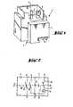
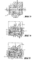
- the overcurrent protection switching element 1 shown in FIGS. 1-5 has a housing 2, from whose mounting side 3 the pivot 5 provided for engagement in the device switch 4 protrudes in the axial direction.
- a contact element 6 also protrudes essentially in the axial direction from the attachment side 3 and establishes the electrical connection to the device switch 4.
- a connection contact 8 is provided on the side 7 opposite the mounting side 3.
- the device switch 4 is designed as a two-pole on / off switch. For this purpose, this is provided with two contact rockers 9, 10, the first contact rocker 9 opening and closing the current path between the first input contact 11 and the first output contact 12 and the second contact rocker 10 the current path between the second input contact 13 and the contact element 6 opens and closes.
- a bimetal 14 and a protective switching contact 15 are connected in series, which has a fixed contact 16 and a movement contact 17.
- the protective switch contact 15 is closed via the coupling element 19 that produces the kinematic coupling between the device switch 4 and the overcurrent protection switch 1 and is held in this latching position by a latching device 20 until the locking device 20 is unlocked by thermally triggered bending of the bimetal 14 and the protective switch contact 15 opens.
- the protective switch contact 15 is closed again when the contact rocker 9, 10 of the device switch 4 is opened again.
- the pivot 5 is substituted on the device switch 4 turned inner end 21 is provided with a transmission disk 22 which is supported with its first end face 23 facing the device switch 4 on the inside 24 of the attachment side 3 of the housing 2.
- the free end face 25 of the transmission disk 22 has a trench-shaped recess 26 oriented in the radial direction, which runs through the disk center 27.
- the recess 26 is delimited on both sides by projections 28 which are provided with inclined surfaces 29 which run in the trench-shaped recess 26.
- the latching device 20 essentially consists of the latching bracket 30, which is equipped with two latching arms 31 projecting parallel from the transmission disk 22 in the axial direction. At the free ends 32 of the locking arms 31 locking hooks 33 are provided, which protrude at right angles and in the same direction in parallel from the free ends 32 of the locking arms 31. Furthermore, the locking bracket 31 is provided at its end facing the transmission disc 22 with a roof-shaped locking edge 34 which lies in the unlocked position in the trench-shaped recess 26 of the transmission disc 22 and upon rotation of the transmission disc on the inclined surfaces 29 of the Projections 28 slides on and thereby pushes the locking bracket 30 away from the transmission disk 22 in the axial direction.
- the displacement takes place against a spring force directed against the transmission disk 22, which is exerted by a leaf spring 35 which extends through the housing 2 in the radial direction.
- the pressure lug 38 is arranged such that it is radially offset with respect to the latching edge 34 such that a torque is continuously exerted on the latching bracket 30 by the spring pressure, which torque is directed clockwise in FIGS.
- latching bracket 30 If the latching bracket 30 is now axially pushed away from the transmission disk 22 by the projections 28 of the transmission disk 22, the latching hooks 33 snap behind latching projections 39, which are formed on the housing 2, due to the clockwise torque.
- the movement contact 17 arranged at the swiveling end 40 of the leaf spring 35 is pressed onto the fixed contact 16, whereby the protective switch contact 15 is closed.
- the contact pressure required for good contact is ensured by the fact that the pressure lug 38 acts on the leaf spring 35 with a radial distance from the pivoting end 40 thereof, so that the area of the leaf spring 35 lying between the pivoting end 40 and the pressure lug 38 is still somewhat affected by the axial pressure exerted by the transmission disk 22 is bent.
- the bimetal 14 is provided, which extends essentially parallel to the leaf spring 35 across the housing 2.
- the bimetal 14 itself is designed as a strip which is elongated in the radial direction and is fastened with its first end 41 to the second side wall 42 of the housing 2.
- an adjusting screw 44 is screwed in the axial direction, which has an angle with its end facing the transmission disk 22.
- lever 45 acted upon, from the opposite side of the locking hook 33 of the locking bracket 30 in the essential Chen protrudes in the radial direction and is attached centrally between the two locking arms 31.
- the angle lever 45 is relatively long compared to the locking hook 33, so that a small axial pressure exerted by the bimetal 14 on the radially outer end of the angle lever 45 is sufficient to pull out the locking hook 33 behind the locking projections 39 and to unlock the locking device.
- the unlatching can only take place when the contact rockers 9 of the device switch 4 are closed and a current flows through the bimetal 14. If the contact rockers 9, 10 are in the closed position, the trench-shaped recess 26 of the transmission disk 22 and the roof-shaped latching edge 34 of the latch bracket 30 are parallel, so that the latch bracket can move axially toward the transmission disk 22 as a whole. If, on the other hand, the contact rockers 9, 10 of the device switch 4 are open, the projections 28 of the transmission disk 22 touch the latching edge 34, as a result of which unlocking is not possible. However, this is not harmful since in this switched-off position of the device switch 4 no current flows through the bimetal 14 anyway.
- the following measures are taken for mounting and guiding the locking bracket 30 in the housing 2:
- the grooves 46 are designed to be open at their end axially facing away from the transmission disk 22 such that one side of the grooves 46 forms the latching projections 39. If the latching bracket 30 is pressed away from the latter by rotating the transmission disk 22 in the axial direction, the latching hooks 33 slide out of the respective groove 46 and hook behind the latching projection 39 arranged at the end of the groove 46 by slightly pivoting the entire latching bracket 30 (in FIG 4 and 5 clockwise).
- the grooves 46 thus allow an axial displacement of the locking bracket 30 and a pivoting movement when the locking position is reached.
- the width of the locking arms 31 in the axial area of the locking edge 34 corresponds essentially to the width of the grooves 46.
- the locking arms 31 are rounded in this area so that they are guided through the grooves 46 in the area of the locking edge 34 when pivoted.
- a the locking bracket 30 is guided further by the angle lever 45, which is guided on both sides in an elongated hole 47 in the longitudinal direction of the leaf spring 35.
- the fixed end 36 of the leaf spring 35 is welded to a first mounting plate 48 made of metallic material, which in turn is in a pocket-like first housing recess 49 is mounted such that it can be inserted into the pocket-like housing recess 49 from the housing side facing away from the transmission disc 22.
- the fixed contact 16 is mounted on a second mounting plate 50 in a second housing recess 51 opposite the first housing recess 49 in an equivalent manner.
- the second mounting plate 50 is bent at right angles in such a way that its protruding part 52 projects substantially radially inward from the second side wall 42 of the housing 2.
- the fixed contact 16 is welded onto the protrusion 52.
- the first mounting plate 48 and the second mounting plate 50 are in the housing recesses 49, 51 in the mounting position tion is noted that the housing wall opposite the transmission disk 22 is formed by a housing cover 53 which can be placed on the housing 2, the inside of which cover 54 acts on and holds the edges 55 of the mounting plates 48, 50 directed away from the adjusting disk 22.
- the housing cover 53 is provided with an adjustment opening 56 in the region of the adjusting screw 44, which is screwed into the movement end 43 of the bimetal 14.
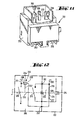
- FIGS. 6-10 starting current limit switch.
- the description of this figure is limited to the parts, the design and function of which differ from the exemplary embodiment “overcurrent protection switching element” shown in FIGS. 1-5.
- the reference numerals in FIGS. 6-10 are increased by the number 100 compared to those in FIGS. 1-5.
- the housing 102 of the starting current limit switch 101 shown in FIG. 6 is essentially identical to the housing 2 of the overcurrent protection switching element 1, only connection tabs 157 and 158 protrude from the first side wall 137 and from the second side wall 142 of the housing 102.
- connection contact 106 is directly connected to the movement contact 117 via the current path 159.
- the connection contact 108 can be connected directly to the contact element 106 via the protective switch contact 115.
- the connection contact tab 157 is connected to the current path 159, while the connection contact tab 158 is connected to the first end of the bimetal 114, which is also U-shaped.
- the second end of the bimetal 114 is connected directly to the connection contact 108.
- a series resistor 160 is connected between the two connection contact tabs 157, 158 which are led out of the housing 102. If the protective switch contact 115 is open, the current flows from the second input contact 113 via the series resistor 160 and the bimetal 114 to the connection contact 108. On the other hand, if the protective switch contact 115 is closed, the current flows directly from the second input contact 113 to the connection contact 108 when the device switch 104 is switched on .
- the protective switch contact 115 Only when the device switch 104 is switched off again is the protective switch contact 115 opened again, so that when the device switch 104 is switched on again, the starting current flowing through the switch combination flows via the current path containing the series resistor 160 and the bimetal 114.
- the opening of the protective switch contact 115 when the device switch 104 is switched off takes place in that, in contrast to the example of the overcurrent protective switching element shown in FIGS. 1-5, the fixed contact 116 of the start-up Current limiting switch 101 is not on the side of the movement contact 117 facing away from the transmission disk 122, but rather between the attachment side 103 and the movement contact 117.
- the bias of the leaf spring 135 directed against the mounting side 103 ensures that the protective switch contact 115 is closed in the release position, while the protective switch contact 115 is caused by the axial pressure exerted by the transmission disk 122 on the latching bracket 130 or by the locking of the latching hooks 133 behind the latching projections 139 remains open in the locked position.
- FIGS. 11-15 zero voltage protection switch.
- the description of these figures is likewise limited only to the parts whose function or arrangement has been modified compared to FIGS. 1-5.
- the reference symbols in FIGS. 11-15 are increased by the number 200 compared to the reference symbols in FIGS. 1-5.
- the zero-voltage protection switch 201 has a housing 202, from the mounting side 203 of which, in addition to the contact element 206 and the pivot pin 205, a further contact element 261 for engaging in the current supply of the Device switch 204 engages.
- a further external connection contact 262 is provided on the side 207 of the housing 202 opposite the mounting side 203.
- a zero voltage relay 263 is provided in the device on / off switch 204, the coil 264 of which is connected with its first coil end 265 to the movement end 217 of the protective switching contact 215 and the second coil end 266 thereof to the first input contact 211 .
- a locking device 267 of the zero-voltage relay engages the contact rockers 209, 210 in such a way that they open when the voltage in the coil 264 drops. The contact rockers 209, 210 are only closed when the device switch 204 is switched on again.
- the voltage drop in the coil 264 is caused by the opening of the protective switch contact 215, which is unlocked by the bimetal 214 in the event of an overcurrent. Unlocking takes place in the same way as for the overcurrent protection switch described at the beginning.
- the zero-voltage relay 263 therefore has a dual function, namely opening the contact rockers 209, 210 in the event of a zero voltage and opening of the contact rockers 209, 210 in the event of an overcurrent, since the voltage in the zero voltage coil 264 drops as described by opening the protective switch contact 215.
- the fixed contact 216 is not connected to one end of the bimetal 14 as in the example of the overcurrent protection switch shown at the beginning, but to the further contact element 261 which, when the switching rocker 210 of the device switch 204 is closed, makes an electrical connection to the bimetal 214.
Landscapes
- Breakers (AREA)
- Thermally Actuated Switches (AREA)
Priority Applications (1)
| Application Number | Priority Date | Filing Date | Title |
|---|---|---|---|
| AT81102572T ATE5674T1 (de) | 1980-07-02 | 1981-04-06 | Schutzschaltelement zum anbau an einen als drehschalter ausgebildeten geraete-ein/ausschalter. |
Applications Claiming Priority (3)
| Application Number | Priority Date | Filing Date | Title |
|---|---|---|---|
| DE19803025013 DE3025013A1 (de) | 1980-07-02 | 1980-07-02 | Schutzschaltelement zum anbau an einen als drehschalter ausgebildeten geraete-ein/ausschalter |
| DE8017765U DE8017765U1 (de) | 1980-07-02 | 1980-07-02 | Schutzschaltelement zum Anbau an einen als Drehschalter ausgebildeten Geräte-Ein/Ausschalter |
| DE3025013 | 1980-07-02 |
Publications (2)
| Publication Number | Publication Date |
|---|---|
| EP0043406A1 true EP0043406A1 (fr) | 1982-01-13 |
| EP0043406B1 EP0043406B1 (fr) | 1983-12-21 |
Family
ID=25786375
Family Applications (1)
| Application Number | Title | Priority Date | Filing Date |
|---|---|---|---|
| EP81102572A Expired EP0043406B1 (fr) | 1980-07-02 | 1981-04-06 | Elément interrupteur de protection pour être ajouté à un appareil interrupteur construit comme interrupteur rotatif |
Country Status (2)
| Country | Link |
|---|---|
| EP (1) | EP0043406B1 (fr) |
| DE (2) | DE8017765U1 (fr) |
Cited By (1)
| Publication number | Priority date | Publication date | Assignee | Title |
|---|---|---|---|---|
| US6483418B1 (en) * | 2000-08-18 | 2002-11-19 | Texas Instruments Incorporated | Creep acting miniature thermostatic electrical switch and thermostatic member used therewith |
Citations (6)
| Publication number | Priority date | Publication date | Assignee | Title |
|---|---|---|---|---|
| DE307336C (fr) * | ||||
| DE709683C (de) * | 1938-06-23 | 1941-08-23 | Aeg | Schutzeinrichtung fuer Induktionsmotoren mit druckknopfgesteuertem Motorschutzschalter |
| CH225650A (de) * | 1940-07-27 | 1943-02-15 | Licentia Gmbh | Bimetallauslöser. |
| US2354157A (en) * | 1942-07-09 | 1944-07-18 | Westinghouse Electric & Mfg Co | Enclosed circuit breaker |
| US2555035A (en) * | 1948-08-06 | 1951-05-29 | Bulldog Electric Prod Co | Circuit breaker |
| DE1040665B (de) * | 1952-08-19 | 1958-10-09 | App | Mehrpoliger Motorschutzschalter |
-
1980
- 1980-07-02 DE DE8017765U patent/DE8017765U1/de not_active Expired
- 1980-07-02 DE DE19803025013 patent/DE3025013A1/de not_active Withdrawn
-
1981
- 1981-04-06 EP EP81102572A patent/EP0043406B1/fr not_active Expired
Patent Citations (6)
| Publication number | Priority date | Publication date | Assignee | Title |
|---|---|---|---|---|
| DE307336C (fr) * | ||||
| DE709683C (de) * | 1938-06-23 | 1941-08-23 | Aeg | Schutzeinrichtung fuer Induktionsmotoren mit druckknopfgesteuertem Motorschutzschalter |
| CH225650A (de) * | 1940-07-27 | 1943-02-15 | Licentia Gmbh | Bimetallauslöser. |
| US2354157A (en) * | 1942-07-09 | 1944-07-18 | Westinghouse Electric & Mfg Co | Enclosed circuit breaker |
| US2555035A (en) * | 1948-08-06 | 1951-05-29 | Bulldog Electric Prod Co | Circuit breaker |
| DE1040665B (de) * | 1952-08-19 | 1958-10-09 | App | Mehrpoliger Motorschutzschalter |
Cited By (1)
| Publication number | Priority date | Publication date | Assignee | Title |
|---|---|---|---|---|
| US6483418B1 (en) * | 2000-08-18 | 2002-11-19 | Texas Instruments Incorporated | Creep acting miniature thermostatic electrical switch and thermostatic member used therewith |
Also Published As
| Publication number | Publication date |
|---|---|
| EP0043406B1 (fr) | 1983-12-21 |
| DE8017765U1 (de) | 1980-10-30 |
| DE3025013A1 (de) | 1982-02-04 |
Similar Documents
| Publication | Publication Date | Title |
|---|---|---|
| EP0543208B1 (fr) | Disjoncteur de protection avec bascule | |
| DE2721162C2 (de) | Überstromschutzschalter mit Ein- und Ausschaltwippe | |
| EP1203385B1 (fr) | Ensemble coupe-circuit multipolaire pour jeux de barres collectrices | |
| EP0616347B1 (fr) | Disjoncteur multipolaire | |
| EP0268098B1 (fr) | Appareil de commutation électrique, en particulier pour commande de puissance | |
| EP1405325B1 (fr) | Appareil de commutation avec mecanisme de verrouillage | |
| DE670790C (de) | Thermisch wirkender Selbstschalter | |
| EP0222181A1 (fr) | Disjoncteur de surintensité | |
| EP0391086B1 (fr) | Dispositeur de protection à courant excessif commandé par un bouton-poussoir | |
| EP0347592B1 (fr) | Dispositif de verrouillage de porte pour appareils électriques | |
| DE1538529A1 (de) | Mehrpoliger UEberstromschalter | |
| DE3516217C2 (fr) | ||
| DE69303097T2 (de) | Schwenkhebelbetätigungsmechanismus für Schutzschalter mit Phasen- und Neutralleiter | |
| EP1353349A2 (fr) | Interrupteur auxiliaire | |
| EP2246871B1 (fr) | Disjoncteur pour assurer un circuit | |
| DE3037355A1 (de) | Schutzschalter kompakter bauart mit einem ausloesestift | |
| DE2651158A1 (de) | Abschalter, insbesondere mehrpoliger abschalter | |
| DE3119165A1 (de) | Selbstschalter als baueinheit aus einem leitungsschutzschalter sowie hilfs- und signalschaltern | |
| EP0043406B1 (fr) | Elément interrupteur de protection pour être ajouté à un appareil interrupteur construit comme interrupteur rotatif | |
| EP0147629B1 (fr) | Disjoncteur de protection | |
| EP0408982B1 (fr) | Disjoncteur de surintensité | |
| DE2805182C2 (de) | Einstellvorrichtung fur den Ausloser eines elektrischen Schaltgerates | |
| EP0849759A1 (fr) | Appareil de coupure pour une installation électrique | |
| DE2532734A1 (de) | Mehrpoliger druckschalter mit ueberstromausloesung | |
| EP0851449B1 (fr) | Appareil de commutation pour une installation électrique |
Legal Events
| Date | Code | Title | Description |
|---|---|---|---|
| PUAI | Public reference made under article 153(3) epc to a published international application that has entered the european phase |
Free format text: ORIGINAL CODE: 0009012 |
|
| AK | Designated contracting states |
Designated state(s): AT CH DE FR GB IT |
|
| 17P | Request for examination filed |
Effective date: 19820115 |
|
| ITCL | It: translation for ep claims filed |
Representative=s name: RICCARDI SERGIO & CO. |
|
| ITF | It: translation for a ep patent filed | ||
| GRAA | (expected) grant |
Free format text: ORIGINAL CODE: 0009210 |
|
| AK | Designated contracting states |
Designated state(s): AT CH DE FR GB IT LI |
|
| REF | Corresponds to: |
Ref document number: 5674 Country of ref document: AT Date of ref document: 19840115 Kind code of ref document: T |
|
| REF | Corresponds to: |
Ref document number: 3161687 Country of ref document: DE Date of ref document: 19840126 |
|
| ET | Fr: translation filed | ||
| PLBE | No opposition filed within time limit |
Free format text: ORIGINAL CODE: 0009261 |
|
| STAA | Information on the status of an ep patent application or granted ep patent |
Free format text: STATUS: NO OPPOSITION FILED WITHIN TIME LIMIT |
|
| 26N | No opposition filed | ||
| PGFP | Annual fee paid to national office [announced via postgrant information from national office to epo] |
Ref country code: DE Payment date: 19910221 Year of fee payment: 11 |
|
| PGFP | Annual fee paid to national office [announced via postgrant information from national office to epo] |
Ref country code: GB Payment date: 19910328 Year of fee payment: 11 |
|
| PGFP | Annual fee paid to national office [announced via postgrant information from national office to epo] |
Ref country code: FR Payment date: 19910419 Year of fee payment: 11 |
|
| PGFP | Annual fee paid to national office [announced via postgrant information from national office to epo] |
Ref country code: AT Payment date: 19910424 Year of fee payment: 11 |
|
| ITTA | It: last paid annual fee | ||
| PGFP | Annual fee paid to national office [announced via postgrant information from national office to epo] |
Ref country code: CH Payment date: 19910521 Year of fee payment: 11 |
|
| PG25 | Lapsed in a contracting state [announced via postgrant information from national office to epo] |
Ref country code: GB Effective date: 19920406 Ref country code: AT Effective date: 19920406 |
|
| PG25 | Lapsed in a contracting state [announced via postgrant information from national office to epo] |
Ref country code: LI Effective date: 19920430 Ref country code: CH Effective date: 19920430 |
|
| GBPC | Gb: european patent ceased through non-payment of renewal fee | ||
| PG25 | Lapsed in a contracting state [announced via postgrant information from national office to epo] |
Ref country code: FR Effective date: 19921230 |
|
| REG | Reference to a national code |
Ref country code: CH Ref legal event code: PL |
|
| PG25 | Lapsed in a contracting state [announced via postgrant information from national office to epo] |
Ref country code: DE Effective date: 19930101 |
|
| REG | Reference to a national code |
Ref country code: FR Ref legal event code: ST |