EP0222181A1 - Disjoncteur de surintensité - Google Patents
Disjoncteur de surintensité Download PDFInfo
- Publication number
- EP0222181A1 EP0222181A1 EP86114120A EP86114120A EP0222181A1 EP 0222181 A1 EP0222181 A1 EP 0222181A1 EP 86114120 A EP86114120 A EP 86114120A EP 86114120 A EP86114120 A EP 86114120A EP 0222181 A1 EP0222181 A1 EP 0222181A1
- Authority
- EP
- European Patent Office
- Prior art keywords
- push button
- switch
- housing
- bimetal
- switching
- Prior art date
- Legal status (The legal status is an assumption and is not a legal conclusion. Google has not performed a legal analysis and makes no representation as to the accuracy of the status listed.)
- Granted
Links
- 238000001514 detection method Methods 0.000 claims abstract 3
- 238000009434 installation Methods 0.000 claims description 9
- 230000000994 depressogenic effect Effects 0.000 claims description 4
- 239000011810 insulating material Substances 0.000 claims description 4
- 238000010438 heat treatment Methods 0.000 description 8
- 239000004020 conductor Substances 0.000 description 3
- 230000000694 effects Effects 0.000 description 2
- 238000003780 insertion Methods 0.000 description 2
- 230000037431 insertion Effects 0.000 description 2
- 238000009413 insulation Methods 0.000 description 2
- 239000000463 material Substances 0.000 description 2
- 238000004804 winding Methods 0.000 description 2
- RNFJDJUURJAICM-UHFFFAOYSA-N 2,2,4,4,6,6-hexaphenoxy-1,3,5-triaza-2$l^{5},4$l^{5},6$l^{5}-triphosphacyclohexa-1,3,5-triene Chemical compound N=1P(OC=2C=CC=CC=2)(OC=2C=CC=CC=2)=NP(OC=2C=CC=CC=2)(OC=2C=CC=CC=2)=NP=1(OC=1C=CC=CC=1)OC1=CC=CC=C1 RNFJDJUURJAICM-UHFFFAOYSA-N 0.000 description 1
- 238000005452 bending Methods 0.000 description 1
- 238000006073 displacement reaction Methods 0.000 description 1
- 239000003063 flame retardant Substances 0.000 description 1
- 238000007654 immersion Methods 0.000 description 1
- 238000002372 labelling Methods 0.000 description 1
- 238000004519 manufacturing process Methods 0.000 description 1
- 230000007420 reactivation Effects 0.000 description 1
- 239000012815 thermoplastic material Substances 0.000 description 1
- 230000007704 transition Effects 0.000 description 1
Images



Classifications
-
- H—ELECTRICITY
- H01—ELECTRIC ELEMENTS
- H01H—ELECTRIC SWITCHES; RELAYS; SELECTORS; EMERGENCY PROTECTIVE DEVICES
- H01H73/00—Protective overload circuit-breaking switches in which excess current opens the contacts by automatic release of mechanical energy stored by previous operation of a hand reset mechanism
- H01H73/22—Protective overload circuit-breaking switches in which excess current opens the contacts by automatic release of mechanical energy stored by previous operation of a hand reset mechanism having electrothermal release and no other automatic release
- H01H73/30—Protective overload circuit-breaking switches in which excess current opens the contacts by automatic release of mechanical energy stored by previous operation of a hand reset mechanism having electrothermal release and no other automatic release reset by push-button, pull-knob or slide
- H01H73/306—Protective overload circuit-breaking switches in which excess current opens the contacts by automatic release of mechanical energy stored by previous operation of a hand reset mechanism having electrothermal release and no other automatic release reset by push-button, pull-knob or slide the push-button supporting pivotally a combined contact-latch lever
Definitions
- the known overcurrent protection switch of the type mentioned is characterized by a very narrow design, so that a large number of such switches can be accommodated in a space-saving manner.
- the manually operable device for deflecting the bimetal is formed by a second push button, which is displaceably mounted in the switch housing parallel to the push button causing the switch-on and acted upon by a spring pushing it back into its inactive position.
- This arrangement of a second push button for manually switching off the switch is technically and also spatially complex.
- the invention has for its object to design a switch of the type mentioned without sacrificing its functions so that it requires less space for accommodating its functional parts and can be manufactured with less manufacturing and material costs.
- This object is achieved by the features listed in the characterizing part of claim 1.
- the invention eliminates the need for a second push button to deflect the bimetal and thereby arrange release of the switch-off movement. Rather, this second push button in the form of the deflection button is a component of the single push button of the switch which is used for switching on.
- the length of the displacement path of the push button has only been increased somewhat in comparison to the known switch mentioned at the outset. The push button can be pushed a little deeper into the switch housing than is necessary for the function of the known switch mentioned at the beginning.
- the bimetal is deflected.
- this deflection has no effect on the contact bridge. If, on the other hand, the push button is fully pressed when the switch is switched on, the deflection of the bimetal that occurs due to its deflection button causes the contact bridge to be released by the bimetal and thus triggers the automatic switch-off under the pressure of the switching spring.
- the characterizing features of claim 2 result in a particularly space-saving design of the switch according to the invention.
- it is suitable for installation in a known manner in double-D-shaped cutouts in control panels or the like instead of conventional fuse links. Thanks to its features of the invention, the switch does not require more space than conventional fuses, even in the installation depth, and yet it has double insulation in the actuation area and the necessary distances from the live parts.
- the identification feature of claim 5 provides particularly good insulation of the live parts guaranteed by the push button accessible from the handling touch.
- the guide piece also fulfills a multiple function through the labeling features of claims 6 and 7.
- the push-button assembly can be pre-assembled with the guide piece in a simple manner for final assembly of the switch in the housing half previously equipped with the bimetal and the connecting contacts. It then only needs to be placed on the other half of the housing and pressed together with the previously fitted housing half. Both housing halves are then clamped together in their final assembly position by the guide piece. Finally, the mutual, definitely non-detachable riveting between the two housing halves can be carried out in a simple manner.
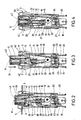
- the housing of the switch consists of the two housing halves 1, 2 molded from thermoplastic material. Their material is resistant to high temperatures, leakage current and largely flame retardant. It is also provided with great strength, which also offers good bending rigidity for the spring hooks 3 for fastening the device in the installation opening 4 of a control panel 5.
- the switch can be actuated by a push button 6 protruding from one end of the switch.
- the push button 6, which is made of insulating material, is firmly connected to the same switching rod 7, the axis 8 of which lies in the central longitudinal plane of the switch.
- the central longitudinal plane is also the parting plane (parting line 9) between the two housing halves 1, 2.
- the switching rod 7 carries at its lower end a flange-like widening 10 as a support for the switching spring 11, which surrounds the switching rod 7 and on the push-button-side end of the contact bridge 12 with its horizontal leg 13 rests.
- the contact bridge 12 has the shape of an angle lever, the horizontal leg 13 of which is approximately at a right angle to the vertical leg 14.
- the contact bridge 12 electrically connects the contact piece 15 of the bimetal 16 to the contact connection 17.
- the bimetal 16 is fastened to the housing by means of a bimetal support 18, which at the same time represents the connection for the direct bimetal heating.
- the bimetal 16 is also wound with a heating winding 19 for optional indirect heating, which can be applied to the voltage via the heating conductor connection 20.
- the contact connection 17, the bimetallic support 18 and the heating conductor connection 20 are fastened to the switch housing base 21 opposite the push button side 6, specifically there in insertion slots 22 or in the parting joint between the two housing halves 1, 2.
- the bimetal carrier 18 or the bimetal 16 is fastened with the fastening screw 23 screwed in from the outside.
- the bimetal is adjusted in a known manner by the cone end 24 of the adjusting screw 25 which can be screwed in parallel to the fastening screw 23 via the bimetal shoulder 26.
- the horizontal leg 13 of the contact bridge 12 locks under the pressure of the switching spring 11 behind or under the contact piece 15 of the bimetal 16. In this position, the horizontal leg 13 assumes a perpendicular position to the axis 8 of the switching rod 7, because likewise under the pressure of the Switch spring 11 of the vertical leg 14 of the contact bridge 12 abuts with its contact piece 27 on the contact terminal 17 and is prevented from pivoting clockwise.
- the shift rod 7 is mounted in a longitudinally displaceable manner in a guide piece 28 which is also made of an insulating material.
- the leader 28 is fastened between contact bridge 12 and push button 6 on both housing halves 1, 2. It seals off the housing parts 29 containing the live parts (bimetal 16, contact piece, contact bridge 12, contact connection 17) and facing the switch housing bottom 21 from the receiving space of the push button 6 located inside the housing.
- the guide piece 28 forms the counter bearing for the push button spring 30 which acts on the push button 6 against the pushing direction 31.
- the guide piece 28 is provided on its side facing the housing base 21 with an inclined surface forming the oblique stop 32.
- the oblique stop 32 when acted upon by the contact bridge 12 under the influence of the switching spring 11, causes the oblique position of the contact bridge 12 shown in FIG. 3 in the switched-off position.
- the guide piece 28 is provided with the spring hooks 33 which clamp the two housing halves 1, 2 together.
- the guide piece 28 has fitting guide pins 34 which interact with the housing halves 1, 2 and which correspond to corresponding guide recesses 35 in the housing halves 1, 2.
- the through openings 36 for the spring hook 33 are arranged.
- the guide piece 28 also forms the end stop for the depressed push button 6.
- the two housing halves 1, 2 are riveted together in their end region on the line connection side by the rivet 37.
- the vertical leg 14 of the contact bridge 12 is provided on both sides with a recess 38, in each of which a projection 39 of the widening 10 of the switching rod 7 engages when the Contact bridge 12 is in a corresponding relative position to the widening 10 or the projections 39, namely in the inclined position adjacent to the oblique stop 32.
- the pushbutton 6 is provided with a deflecting nose 40 which runs next to the switching rod 7 and which, in the depressed pushbutton position (FIGS. 4, 6, 9), deflects the bimetal 16 clockwise to release the switch-off movement with reference to the FIG.
- the deflection nose 40 acts on the contact piece 15 of the bimetal 16 with a corresponding inclined surface 41.
- the end of the tubular switch housing consisting of the two housing halves 1, 2 surrounding the push button 6 is provided with a flange-like stop 42 for abutment against the outer edge of the installation opening 4, for example of the control panel 5.
- the push button 6 can be provided with a cap 43 for color coding.
- Plug-in locks 44 are formed on the connections 17, 18, 20, which have the effect that the plug-in sleeves to be plugged on can only be plugged on in a certain rotational position. Due to the arrangement of the connections 17, 18, 20 and the corresponding release direction of the plug-on locks 44, the prescribed creepage distances and clearances can be adhered to.
- the switch is in the switch-on position shown in Fig. 2 or 8.
- the push button is used to switch off 6 pressed in the printing direction 31.
- the deflection nose 40 deflects the free end of the bimetal 16 clockwise with its inclined surface 41.
- the contact piece 15 of the bimetal 16 gets out of engagement behind the horizontal leg 13 of the contact bridge 12.
- the contact bridge 12 is consequently torn out of contact not only with the contact piece 15 of the bimetal 16, but also the contact terminal 17 by the switching spring 11.
- the contact bridge ultimately strikes against the underside of the guide piece 28.
- the push button spring 30 pushes it into its starting position which is furthest from the housing (FIG. 3), which thereby simultaneously signals the switch-off position .
- the vertical leg 14 of the contact bridge 12 is released from contact with the widening 10 of the switching rod 7, so that the contact bridge 12 with its horizontal leg 13 can lie flush against the oblique stop 32 which forms the underside of the guide piece 28.
- the contact bridge 12 assumes the inclined position shown in FIG. 3, in which the projections 39 of the widening 10 of the switching rod 7 fall into the recesses 38 of the vertical leg 14 of the contact bridge 12.
- the contact bridge 12, which is in the switched-off position is thus prepared for reactivation.
- the restart is initiated by pressing button 6 again.
- the projections 39 lying in the recesses 38 take the contact bridge 12 downward in the pressure direction 31.
- the bottom dead center position is in Fig. 6 is shown schematically.
- the contact bridge 12 maintains its inclined position.
- the deflection nose 40 deflects the bimetal 16 clockwise. If the push button is now released, the deflection nose 40 first comes out of contact with the contact piece 15 of the bimetal 16.
- the bimetal 16 swivels back into the vertical starting position under its own elasticity (FIG. 7). In this vertical starting position, the contact piece 15 of the bimetal 16 is in the way of the free end of the horizontal leg 13 of the contact bridge 12.
- Bimetal release When the bimetal 16 is automatically deflected by overcurrent, that is to say by direct or indirect heating of the bimetal 16, the free end of the horizontal leg 13 of the contact bridge 12 is released by the contact piece 15. The contact bridge swings under the pressure of the switching spring 11 into the stop position on the guide piece 28. The switch-off movement is supported by the push-button spring, which at the same time pushes the push-button up into the switch-off position (FIG. 3).
- the push button 6 assumes its maximum immersion position from the housing, which signals the off position of the switch from the outside.
- the switch is switched on again manually by pressing the pushbutton 6, as described above under "Manual actuation".
Landscapes
- Breakers (AREA)
- Push-Button Switches (AREA)
Applications Claiming Priority (2)
| Application Number | Priority Date | Filing Date | Title |
|---|---|---|---|
| DE8530597U | 1985-10-29 | ||
| DE8530597U DE8530597U1 (de) | 1985-10-29 | 1985-10-29 | Überstromschutzschalter |
Publications (2)
| Publication Number | Publication Date |
|---|---|
| EP0222181A1 true EP0222181A1 (fr) | 1987-05-20 |
| EP0222181B1 EP0222181B1 (fr) | 1989-09-06 |
Family
ID=6786721
Family Applications (1)
| Application Number | Title | Priority Date | Filing Date |
|---|---|---|---|
| EP86114120A Expired EP0222181B1 (fr) | 1985-10-29 | 1986-10-11 | Disjoncteur de surintensité |
Country Status (4)
| Country | Link |
|---|---|
| US (1) | US4704594A (fr) |
| EP (1) | EP0222181B1 (fr) |
| JP (1) | JPS62195825A (fr) |
| DE (2) | DE8530597U1 (fr) |
Families Citing this family (17)
| Publication number | Priority date | Publication date | Assignee | Title |
|---|---|---|---|---|
| US5786742A (en) * | 1997-07-14 | 1998-07-28 | Yin; Tien-Ning | Push button switch with override interruption structure |
| TW446174U (en) * | 1999-02-12 | 2001-07-11 | You Tsung Mou | Simplified push-button type breaker switch |
| TW450419U (en) * | 1999-02-12 | 2001-08-11 | You Tsung Mou | Key-type interruptible safety switch |
| TW453504U (en) | 1999-06-24 | 2001-09-01 | You Tsung Mou | Button switch having overload protection function |
| TW515567U (en) | 1999-06-24 | 2002-12-21 | Tsung-Mou You | Push button type switch having overload protection and automatic reload function |
| TW427544U (en) | 1999-06-24 | 2001-03-21 | You Tsung Mou | Pressing-key switch with overload protection function |
| TW456574U (en) | 1999-10-29 | 2001-09-21 | You Tsung Mou | Overload protection push button switch with indirectly driven auto-reset activated mechanism |
| TW475775U (en) | 1999-12-30 | 2002-02-01 | Tsung-Mou You | Overload protection type push button switch having an intermittent retractable activated mechanism |
| TW462531U (en) | 1999-12-30 | 2001-11-01 | You Tsung Mou | Over-load protection type button switch with drawing type auto-reset driven mechanism |
| CA2297948A1 (fr) * | 2000-02-02 | 2001-08-02 | Tsung-Mou Yu | Sectionneur de securite a poussoir |
| TW478641U (en) | 2000-06-13 | 2002-03-01 | Tsung-Mou You | Cyclic type push button switch having overload protection |
| US6469610B1 (en) * | 2000-07-28 | 2002-10-22 | Tsung-Mou Yu | Switch assembly |
| US6552643B2 (en) * | 2000-12-11 | 2003-04-22 | Shang-Hao Chen | Structure of a depress-type safety switch |
| US6496095B2 (en) * | 2001-03-08 | 2002-12-17 | Tsung-Mou Yu | Switch with an override interruption structure |
| US6452125B1 (en) | 2001-03-17 | 2002-09-17 | Tsung-Mou Yu | Switch with an override interruption structure |
| TWI408717B (zh) * | 2010-09-17 | 2013-09-11 | Powertech Ind Co Ltd | 開關模組 |
| EP4517479A1 (fr) * | 2023-08-30 | 2025-03-05 | Ovh | Système de surveillance de température de centre de données pour ensembles montés sur bâti refroidis par liquide |
Citations (3)
| Publication number | Priority date | Publication date | Assignee | Title |
|---|---|---|---|---|
| FR74972E (fr) * | 1958-02-27 | 1961-03-03 | Ellenberger & Poensgen | Disjoncteur à bouton-poussoir |
| FR2355372A1 (fr) * | 1976-06-15 | 1978-01-13 | Heinemann Electric Co | Coupe-circuit a bilame |
| FR2380703A7 (fr) * | 1977-02-15 | 1978-09-08 | Ellenberger & Poensgen | Contacteur-disjoncteur a commande par bilame et a manoeuvre par bouton poussoir avec declenchement libre |
-
1985
- 1985-10-29 DE DE8530597U patent/DE8530597U1/de not_active Expired
-
1986
- 1986-10-11 DE DE8686114120T patent/DE3665512D1/de not_active Expired
- 1986-10-11 EP EP86114120A patent/EP0222181B1/fr not_active Expired
- 1986-10-27 US US06/923,650 patent/US4704594A/en not_active Expired - Lifetime
- 1986-10-29 JP JP61255976A patent/JPS62195825A/ja active Granted
Patent Citations (3)
| Publication number | Priority date | Publication date | Assignee | Title |
|---|---|---|---|---|
| FR74972E (fr) * | 1958-02-27 | 1961-03-03 | Ellenberger & Poensgen | Disjoncteur à bouton-poussoir |
| FR2355372A1 (fr) * | 1976-06-15 | 1978-01-13 | Heinemann Electric Co | Coupe-circuit a bilame |
| FR2380703A7 (fr) * | 1977-02-15 | 1978-09-08 | Ellenberger & Poensgen | Contacteur-disjoncteur a commande par bilame et a manoeuvre par bouton poussoir avec declenchement libre |
Also Published As
| Publication number | Publication date |
|---|---|
| JPH0368500B2 (fr) | 1991-10-28 |
| US4704594A (en) | 1987-11-03 |
| DE8530597U1 (de) | 1986-02-27 |
| DE3665512D1 (en) | 1989-10-12 |
| EP0222181B1 (fr) | 1989-09-06 |
| JPS62195825A (ja) | 1987-08-28 |
Similar Documents
| Publication | Publication Date | Title |
|---|---|---|
| EP0222181B1 (fr) | Disjoncteur de surintensité | |
| DE4129938C2 (fr) | ||
| DE9001448U1 (de) | Schaltvorrichtung mit geschützten Unterbrechern | |
| EP0143981B1 (fr) | Disjoncteur monté sur rails | |
| DE19746621A1 (de) | Schalterverbindungsanordnung | |
| DE2835354A1 (de) | Sprungkontakt-schutzschalter | |
| DE19818058C2 (de) | Schaltgerät mit einer Schaltkammer-Baugruppe | |
| DE3827306A1 (de) | Wasserdichte schalteinrichtung fuer elektrische anlagen | |
| DE1465705B1 (de) | Elektrischer Schnappschalter mit Drueckerhebel | |
| DE8904063U1 (de) | Druckknopfbetätigter Überstromschutzschalter | |
| WO1998010453A1 (fr) | Dispositif electrique pour la vaporisation de substances actives | |
| DE69218025T2 (de) | Elektromechanisches Schaltgerät mit frontalem Zusatzbauteil | |
| DE4406670A1 (de) | Leitungsschutzschalter | |
| DE3037355A1 (de) | Schutzschalter kompakter bauart mit einem ausloesestift | |
| EP0432652A1 (fr) | Interrupteur à fusible actionné manuellement | |
| EP0862784B1 (fr) | Disjoncteur de surintensite | |
| DE3620105C1 (en) | Electrical contact switch | |
| DE3313465A1 (de) | Druckknopfbetaetigter ueberstromschalter | |
| DE2803473C2 (de) | Elektrischer Installationstaster | |
| EP0565008B1 (fr) | Dispositif à bouton de contrÔle pour disjoncteur pour courant de défaut ou à courant différentiel | |
| DE3119181C1 (de) | Sicherungssockel für einen Schmelzeinsatz | |
| DE4003745A1 (de) | Schaltgeraet | |
| DE3110005A1 (de) | "steckdose mit kindersicherung" | |
| DE3146668C2 (de) | Tastschalter | |
| DE2558620C2 (de) | Elektrischer Schalter |
Legal Events
| Date | Code | Title | Description |
|---|---|---|---|
| PUAI | Public reference made under article 153(3) epc to a published international application that has entered the european phase |
Free format text: ORIGINAL CODE: 0009012 |
|
| AK | Designated contracting states |
Kind code of ref document: A1 Designated state(s): CH DE FR GB IT LI SE |
|
| 17P | Request for examination filed |
Effective date: 19870709 |
|
| ITCL | It: translation for ep claims filed |
Representative=s name: RICCARDI SERGIO & CO. |
|
| EL | Fr: translation of claims filed | ||
| 17Q | First examination report despatched |
Effective date: 19890207 |
|
| GRAA | (expected) grant |
Free format text: ORIGINAL CODE: 0009210 |
|
| AK | Designated contracting states |
Kind code of ref document: B1 Designated state(s): CH DE FR GB IT LI SE |
|
| REF | Corresponds to: |
Ref document number: 3665512 Country of ref document: DE Date of ref document: 19891012 |
|
| GBT | Gb: translation of ep patent filed (gb section 77(6)(a)/1977) | ||
| ITF | It: translation for a ep patent filed | ||
| ET | Fr: translation filed | ||
| PLBE | No opposition filed within time limit |
Free format text: ORIGINAL CODE: 0009261 |
|
| STAA | Information on the status of an ep patent application or granted ep patent |
Free format text: STATUS: NO OPPOSITION FILED WITHIN TIME LIMIT |
|
| 26N | No opposition filed | ||
| ITTA | It: last paid annual fee | ||
| EAL | Se: european patent in force in sweden |
Ref document number: 86114120.8 |
|
| PGFP | Annual fee paid to national office [announced via postgrant information from national office to epo] |
Ref country code: CH Payment date: 20011023 Year of fee payment: 16 Ref country code: SE Payment date: 20011023 Year of fee payment: 16 |
|
| REG | Reference to a national code |
Ref country code: GB Ref legal event code: IF02 |
|
| PG25 | Lapsed in a contracting state [announced via postgrant information from national office to epo] |
Ref country code: SE Free format text: LAPSE BECAUSE OF NON-PAYMENT OF DUE FEES Effective date: 20021012 |
|
| PG25 | Lapsed in a contracting state [announced via postgrant information from national office to epo] |
Ref country code: CH Free format text: LAPSE BECAUSE OF NON-PAYMENT OF DUE FEES Effective date: 20021031 Ref country code: LI Free format text: LAPSE BECAUSE OF NON-PAYMENT OF DUE FEES Effective date: 20021031 |
|
| EUG | Se: european patent has lapsed | ||
| REG | Reference to a national code |
Ref country code: CH Ref legal event code: PL |
|
| PGFP | Annual fee paid to national office [announced via postgrant information from national office to epo] |
Ref country code: GB Payment date: 20050929 Year of fee payment: 20 |
|
| PGFP | Annual fee paid to national office [announced via postgrant information from national office to epo] |
Ref country code: FR Payment date: 20051019 Year of fee payment: 20 |
|
| PGFP | Annual fee paid to national office [announced via postgrant information from national office to epo] |
Ref country code: IT Payment date: 20051026 Year of fee payment: 20 |
|
| PGFP | Annual fee paid to national office [announced via postgrant information from national office to epo] |
Ref country code: DE Payment date: 20051230 Year of fee payment: 20 |
|
| PG25 | Lapsed in a contracting state [announced via postgrant information from national office to epo] |
Ref country code: GB Free format text: LAPSE BECAUSE OF EXPIRATION OF PROTECTION Effective date: 20061010 |
|
| REG | Reference to a national code |
Ref country code: GB Ref legal event code: PE20 |