EP0043407A2 - Disposition pour la mesure digitale de différence de phase - Google Patents
Disposition pour la mesure digitale de différence de phase Download PDFInfo
- Publication number
- EP0043407A2 EP0043407A2 EP81102602A EP81102602A EP0043407A2 EP 0043407 A2 EP0043407 A2 EP 0043407A2 EP 81102602 A EP81102602 A EP 81102602A EP 81102602 A EP81102602 A EP 81102602A EP 0043407 A2 EP0043407 A2 EP 0043407A2
- Authority
- EP
- European Patent Office
- Prior art keywords
- output
- frequency divider
- input
- inputs
- phase difference
- Prior art date
- Legal status (The legal status is an assumption and is not a legal conclusion. Google has not performed a legal analysis and makes no representation as to the accuracy of the status listed.)
- Granted
Links
Images

Classifications
-
- G—PHYSICS
- G01—MEASURING; TESTING
- G01R—MEASURING ELECTRIC VARIABLES; MEASURING MAGNETIC VARIABLES
- G01R25/00—Arrangements for measuring phase angle between a voltage and a current or between voltages or currents
- G01R25/08—Arrangements for measuring phase angle between a voltage and a current or between voltages or currents by counting of standard pulses
-
- G—PHYSICS
- G01—MEASURING; TESTING
- G01S—RADIO DIRECTION-FINDING; RADIO NAVIGATION; DETERMINING DISTANCE OR VELOCITY BY USE OF RADIO WAVES; LOCATING OR PRESENCE-DETECTING BY USE OF THE REFLECTION OR RERADIATION OF RADIO WAVES; ANALOGOUS ARRANGEMENTS USING OTHER WAVES
- G01S3/00—Direction-finders for determining the direction from which infrasonic, sonic, ultrasonic or electromagnetic waves, or particle emission, not having a directional significance, are being received
- G01S3/80—Direction-finders for determining the direction from which infrasonic, sonic, ultrasonic or electromagnetic waves, or particle emission, not having a directional significance, are being received using ultrasonic, sonic or infrasonic waves
- G01S3/802—Systems for determining direction or deviation from predetermined direction
- G01S3/805—Systems for determining direction or deviation from predetermined direction using adjustment of real or effective orientation of directivity characteristics of a transducer or transducer system to give a desired condition of signal derived from that transducer or transducer system, e.g. to give a maximum or minimum signal
- G01S3/8055—Systems for determining direction or deviation from predetermined direction using adjustment of real or effective orientation of directivity characteristics of a transducer or transducer system to give a desired condition of signal derived from that transducer or transducer system, e.g. to give a maximum or minimum signal adjusting orientation of a single directivity characteristic to produce maximum or minimum signal
-
- H—ELECTRICITY
- H03—ELECTRONIC CIRCUITRY
- H03L—AUTOMATIC CONTROL, STARTING, SYNCHRONISATION OR STABILISATION OF GENERATORS OF ELECTRONIC OSCILLATIONS OR PULSES
- H03L7/00—Automatic control of frequency or phase; Synchronisation
- H03L7/06—Automatic control of frequency or phase; Synchronisation using a reference signal applied to a frequency- or phase-locked loop
- H03L7/08—Details of the phase-locked loop
- H03L7/099—Details of the phase-locked loop concerning mainly the controlled oscillator of the loop
- H03L7/0991—Details of the phase-locked loop concerning mainly the controlled oscillator of the loop the oscillator being a digital oscillator, e.g. composed of a fixed oscillator followed by a variable frequency divider
- H03L7/0992—Details of the phase-locked loop concerning mainly the controlled oscillator of the loop the oscillator being a digital oscillator, e.g. composed of a fixed oscillator followed by a variable frequency divider comprising a counter or a frequency divider
-
- H—ELECTRICITY
- H04—ELECTRIC COMMUNICATION TECHNIQUE
- H04N—PICTORIAL COMMUNICATION, e.g. TELEVISION
- H04N5/00—Details of television systems
- H04N5/04—Synchronising
- H04N5/12—Devices in which the synchronising signals are only operative if a phase difference occurs between synchronising and synchronised scanning devices, e.g. flywheel synchronising
Definitions
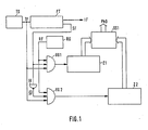
- the three inputs of the first AND gate UG1 and the three inputs of the second AND gate UG2 are each the clock signal TF or the reference pulse sequence RF or the switching signal SF (AND gate UG1) or the inverted switching signal SF (via the inverter stage IV) AND gate UG2) supplied.
- the outputs of the two AND gates UG1, UG2 are each at the counting input of the first and the second up-counter Z1, Z2, the outputs of which are connected to the inputs of the subtracting circuit SS1.
- this connection is the parallel transmission of digital signals, i.e. the respective counts of the two up-counters Z1, Z2 are forwarded in parallel to the assigned inputs of the subtracting circuit SS1, at whose output the phase difference digital signal PhD can be obtained.
Landscapes
- Physics & Mathematics (AREA)
- Engineering & Computer Science (AREA)
- General Physics & Mathematics (AREA)
- Radar, Positioning & Navigation (AREA)
- Remote Sensing (AREA)
- Multimedia (AREA)
- Signal Processing (AREA)
- Measuring Phase Differences (AREA)
- Stabilization Of Oscillater, Synchronisation, Frequency Synthesizers (AREA)
- Manipulation Of Pulses (AREA)
Applications Claiming Priority (2)
| Application Number | Priority Date | Filing Date | Title |
|---|---|---|---|
| DE3025356 | 1980-07-04 | ||
| DE19803025356 DE3025356A1 (de) | 1980-07-04 | 1980-07-04 | Schaltungsanordnung zur digitalen phasendifferenz-messung, deren verwendung in einer synchronisierschaltung und entsprechende synchronisierschaltung |
Publications (3)
| Publication Number | Publication Date |
|---|---|
| EP0043407A2 true EP0043407A2 (fr) | 1982-01-13 |
| EP0043407A3 EP0043407A3 (en) | 1982-02-17 |
| EP0043407B1 EP0043407B1 (fr) | 1985-10-09 |
Family
ID=6106405
Family Applications (1)
| Application Number | Title | Priority Date | Filing Date |
|---|---|---|---|
| EP81102602A Expired EP0043407B1 (fr) | 1980-07-04 | 1981-04-07 | Disposition pour la mesure digitale de différence de phase |
Country Status (5)
| Country | Link |
|---|---|
| US (1) | US4471299A (fr) |
| EP (1) | EP0043407B1 (fr) |
| JP (1) | JPS5744861A (fr) |
| DE (2) | DE3025356A1 (fr) |
| IE (1) | IE51757B1 (fr) |
Cited By (7)
| Publication number | Priority date | Publication date | Assignee | Title |
|---|---|---|---|---|
| EP0121004A1 (fr) * | 1983-03-26 | 1984-10-10 | Deutsche ITT Industries GmbH | Circuit numérique de synchronisation d'un signal vidéo composite |
| EP0225396A1 (fr) * | 1985-12-12 | 1987-06-16 | Deutsche ITT Industries GmbH | Circuit numérique de mesure de phase |
| EP0310088A3 (en) * | 1987-10-01 | 1990-09-12 | Sharp Kabushiki Kaisha | Digital phase-locked loop system |
| WO1992022171A1 (fr) * | 1991-06-05 | 1992-12-10 | Texas Instruments Limited | Procede et appareil destines a detecter une sequence d'impulsions d'horloge de reference |
| EP0725484A1 (fr) * | 1995-01-31 | 1996-08-07 | Siemens Aktiengesellschaft | Procédé et dispositif pour déterminer la différence de phase de signaux d'horloge dans un dispositif de communication |
| DE19830260A1 (de) * | 1998-07-07 | 2000-01-13 | Alcatel Sa | Taktgenerator und Synchronisierungsverfahren |
| DE19844126C1 (de) * | 1998-09-25 | 2000-06-08 | Siemens Ag | Frequenzdetektionsverfahren zur Taktsignalfrequenz-Nachstellung und Frequenzdetektorschaltung zur Durchführung des Verfahrens |
Families Citing this family (28)
| Publication number | Priority date | Publication date | Assignee | Title |
|---|---|---|---|---|
| NL8103705A (nl) * | 1981-08-06 | 1983-03-01 | Philips Nv | Lijnsynchroniseerschakeling voor een beelweergeefinrichting. |
| NL8202685A (nl) * | 1982-07-05 | 1984-02-01 | Philips Nv | Kloksignaalregenerator met hoge stabiliteit. |
| SE434781B (sv) * | 1982-12-21 | 1984-08-13 | Ericsson Telefon Ab L M | Sett att meta en likstrom eller en lagfrekvent vexelstrom |
| AU2592384A (en) * | 1983-03-26 | 1984-09-27 | Itt Industries, Inc. | Digital horizontal synchronization |
| US4543600A (en) * | 1983-09-19 | 1985-09-24 | Rca Corporation | Digital signal phase measuring apparatus as for a phase-locked loop |
| JPS6128070U (ja) * | 1984-07-26 | 1986-02-19 | パイオニア株式会社 | デイジタル周波数位相比較器 |
| US4707653A (en) * | 1985-10-17 | 1987-11-17 | Ampex Corporation | Frequency measurement circuit |
| US4737971A (en) * | 1986-04-07 | 1988-04-12 | American Telephone And Telegraph Company | Synchronization detection circuit |
| AT393053B (de) * | 1987-04-09 | 1991-08-12 | Elin Union Ag | Anordnung zur ermittlung des wiederkehrenden synchronisationszeitpunktes |
| US4922195A (en) * | 1988-12-19 | 1990-05-01 | Westinghouse Electric Corp. | Extraneous frequency detector |
| US5019786A (en) * | 1989-11-17 | 1991-05-28 | The United States Of America As Represented By The United States Department Of Energy | Phase measurement system using a dithered clock |
| US5341031A (en) * | 1990-08-27 | 1994-08-23 | Mitsubishi Denki Kabushiki Kaisha | Stable high speed clock generator |
| US5162910A (en) * | 1990-10-03 | 1992-11-10 | Thomson Consumer Electronics, Inc. | Synchronizing circuit |
| US5103162A (en) * | 1991-03-21 | 1992-04-07 | Westinghouse Electric Corp. | Apparatus for determining when a preselected phase relationship exists between two periodic waveforms |
| JPH04336308A (ja) * | 1991-05-13 | 1992-11-24 | Nec Corp | マイクロコンピュータ |
| US5144170A (en) * | 1991-06-28 | 1992-09-01 | Motorola, Inc. | Circuit and method of aligning clock signals |
| US5371416A (en) * | 1993-04-05 | 1994-12-06 | Motorola, Inc. | Circuit and method of synchronizing clock signals |
| US5442278A (en) * | 1993-09-24 | 1995-08-15 | Acer Peripherals, Inc. | Apparatus for detecting the frequency of an input signal by counting pulses during an input signal cycle |
| US5844622A (en) * | 1995-12-12 | 1998-12-01 | Trw Inc. | Digital video horizontal synchronization pulse detector and processor |
| KR100258332B1 (ko) * | 1997-12-26 | 2000-06-01 | 윤종용 | 싱크검출장치와 그에 따른 광 디스크 재생장치 |
| DE19801732A1 (de) * | 1998-01-19 | 1999-07-22 | Thomson Brandt Gmbh | Schaltung zur Aufbereitung von Synchronsignalen |
| DE19816656C2 (de) * | 1998-04-15 | 2000-08-10 | Suedwestrundfunk Anstalt Des O | Verfahren zum Erzeugen von Frequenzen |
| US7483508B2 (en) * | 2001-11-27 | 2009-01-27 | Texas Instruments Incorporated | All-digital frequency synthesis with non-linear differential term for handling frequency perturbations |
| EP1492226A1 (fr) * | 2003-06-23 | 2004-12-29 | Alcatel | Procédé de surveillance de la stabilité de la fréquence d'un oscillateur de génération d'horloge dans un élément de réseau, et d'indication un signal d'alarme |
| US8283810B2 (en) | 2005-01-21 | 2012-10-09 | C.E. Niehoff & Co. | System and method for generator phase signal monitoring and control of electrical current distribution |
| US8227941B2 (en) * | 2009-07-23 | 2012-07-24 | C.E. Niehoff & Co. | System and method for generator phase signal monitoring and control |
| US9535481B2 (en) | 2012-02-20 | 2017-01-03 | Engineered Electric Company | Power grid remote access |
| US10333532B2 (en) * | 2017-09-07 | 2019-06-25 | Micron Technology, Inc. | Apparatuses and methods for detecting a loop count in a delay-locked loop |
Family Cites Families (12)
| Publication number | Priority date | Publication date | Assignee | Title |
|---|---|---|---|---|
| US2980858A (en) * | 1959-12-07 | 1961-04-18 | Collins Radio Co | Digital synchronization circuit operating by inserting extra pulses into or delayingpulses from clock pulse train |
| US3297947A (en) * | 1963-12-18 | 1967-01-10 | Gen Precision Inc | Apparatus for two signal polarity detecting using alternate quartercycle sampling toeliminate quadrature error |
| US3509476A (en) * | 1965-10-12 | 1970-04-28 | Gen Dynamics Corp | Digital frequency and/or phase measuring system having wide dynamic range |
| US3820022A (en) * | 1972-09-28 | 1974-06-25 | Cubic Corp | Asymmetrical wave digital phase measuring system |
| US4001682A (en) * | 1972-09-28 | 1977-01-04 | Cubic Corporation | Ambiguity free digital averaging phase meter |
| SE379862B (fr) * | 1974-02-07 | 1975-10-20 | Asea Ab | |
| FR2281573A1 (fr) * | 1974-08-09 | 1976-03-05 | Thomson Csf | Appareil de mesure de dephasage introduit par un circuit electronique |
| DE2709270C2 (de) * | 1977-03-03 | 1984-02-23 | Siemens AG, 1000 Berlin und 8000 München | Fernseheinrichtung mit einem Regelkreis für die Frequenz und Phasenlage der Vertikalimpulse |
| FR2396979A1 (fr) * | 1977-07-08 | 1979-02-02 | Thomson Csf | Circuit de mesure du decalage angulaire entre deux impulsions periodiques et dispositif de controle des systemes d'allumage electronique comportant un tel circuit |
| DE2733890A1 (de) * | 1977-07-27 | 1979-02-01 | Siemens Ag | Verfahren zum hochgenauen messen von phasen- und frequenzdifferenzen |
| US4157500A (en) * | 1977-10-31 | 1979-06-05 | Societe d'Exploitation de Produits et de Techniques pour l'Aeronautique & l'Automatique | Multiperiodical phasemeter |
| DD146212A1 (de) * | 1979-09-17 | 1981-01-28 | S Schleicher | Schaltungsanordnung zum digitalen wegmessen bei vergroessertem eindeutigkeitsbereich |
-
1980
- 1980-07-04 DE DE19803025356 patent/DE3025356A1/de not_active Withdrawn
-
1981
- 1981-04-07 DE DE8181102602T patent/DE3172575D1/de not_active Expired
- 1981-04-07 EP EP81102602A patent/EP0043407B1/fr not_active Expired
- 1981-07-02 JP JP56102360A patent/JPS5744861A/ja active Pending
- 1981-07-03 IE IE1497/81A patent/IE51757B1/en unknown
-
1983
- 1983-06-30 US US06/509,979 patent/US4471299A/en not_active Expired - Fee Related
Cited By (11)
| Publication number | Priority date | Publication date | Assignee | Title |
|---|---|---|---|---|
| EP0121004A1 (fr) * | 1983-03-26 | 1984-10-10 | Deutsche ITT Industries GmbH | Circuit numérique de synchronisation d'un signal vidéo composite |
| EP0225396A1 (fr) * | 1985-12-12 | 1987-06-16 | Deutsche ITT Industries GmbH | Circuit numérique de mesure de phase |
| US4721905A (en) * | 1985-12-12 | 1988-01-26 | Intermetall, Division Of Ditti | Digital phase meter circuit |
| EP0310088A3 (en) * | 1987-10-01 | 1990-09-12 | Sharp Kabushiki Kaisha | Digital phase-locked loop system |
| WO1992022171A1 (fr) * | 1991-06-05 | 1992-12-10 | Texas Instruments Limited | Procede et appareil destines a detecter une sequence d'impulsions d'horloge de reference |
| EP0725484A1 (fr) * | 1995-01-31 | 1996-08-07 | Siemens Aktiengesellschaft | Procédé et dispositif pour déterminer la différence de phase de signaux d'horloge dans un dispositif de communication |
| CN1066875C (zh) * | 1995-01-31 | 2001-06-06 | 西门子公司 | 用于测定通信设备中的脉冲信号间相位差的方法及装置 |
| DE19830260A1 (de) * | 1998-07-07 | 2000-01-13 | Alcatel Sa | Taktgenerator und Synchronisierungsverfahren |
| US6181175B1 (en) | 1998-07-07 | 2001-01-30 | Alcatel | Clock generator and synchronizing method |
| DE19844126C1 (de) * | 1998-09-25 | 2000-06-08 | Siemens Ag | Frequenzdetektionsverfahren zur Taktsignalfrequenz-Nachstellung und Frequenzdetektorschaltung zur Durchführung des Verfahrens |
| US6362693B2 (en) | 1998-09-25 | 2002-03-26 | Infineon Technologies Ag | Frequency detection method for adjusting a clock signal frequency and a frequency detector circuit for carrying out the method |
Also Published As
| Publication number | Publication date |
|---|---|
| DE3172575D1 (en) | 1985-11-14 |
| IE811497L (en) | 1982-01-04 |
| EP0043407B1 (fr) | 1985-10-09 |
| US4471299A (en) | 1984-09-11 |
| EP0043407A3 (en) | 1982-02-17 |
| DE3025356A1 (de) | 1982-01-21 |
| IE51757B1 (en) | 1987-03-18 |
| JPS5744861A (en) | 1982-03-13 |
Similar Documents
| Publication | Publication Date | Title |
|---|---|---|
| EP0043407B1 (fr) | Disposition pour la mesure digitale de différence de phase | |
| EP0184254B1 (fr) | Circuit de discrimination des deux trames d'un signal de télévision | |
| DE2400394C3 (de) | Schaltungsanordnung zur digitalen Frequenzteilung | |
| EP0079971B1 (fr) | Circuit digital délivrant un signal binaire lorsque le rapport de fréquence de ligne et de fréquence de trame apparaît | |
| EP0099142B1 (fr) | Procédé et dispositif de démodulation d'un signal d'entrée modulé en fréquence | |
| DE2714219C2 (fr) | ||
| EP0095543B1 (fr) | Circuit intégré digital de chrominance avec amplification régleé | |
| DE69317200T2 (de) | Datenverarbeitungsschaltung | |
| EP0062698A2 (fr) | Circuit d'évaluation pour un transducteur de vitesse de rotation | |
| DE2855301A1 (de) | Tonsignaldetektor | |
| DE3217228C2 (fr) | ||
| DE2613930C3 (de) | Digitaler Phasenregelkreis | |
| DE3329773A1 (de) | Verfahren und anordnung zur zeitgleichen flankenanpassung mehrerer taktsynchroner datenfluesse | |
| DE3832330C2 (de) | Schaltungsanordnung zur Ableitung von horizontalfrequenten und veritikalfrequenten Impulsen | |
| DE2710270B2 (de) | Schaltungsanordnung zur Erzeugung von mit eintreffenden Datenimpulsen synchronisierten Taktimpulsen | |
| DE3246211A1 (de) | Schaltungsanordnung zur detektion von folgen identischer binaerwerte | |
| DE4407948C2 (de) | Schnittstelle | |
| EP0283662B1 (fr) | Méthode et dispositif de traitement de données numériques asynchrones | |
| EP0121004B1 (fr) | Circuit numérique de synchronisation d'un signal vidéo composite | |
| DE2831723C2 (de) | Elektrische Schaltungsanordnung | |
| DE2709726A1 (de) | Impulsdaueranzeigeschaltung | |
| DE2308304C3 (de) | Anordnung zur Schräglaufkompensation bei einem kinematischen Magnetspeicher | |
| DE3136223A1 (de) | Integrierbarer tonfrequenzdetektor | |
| DE3307847A1 (de) | Taktsynchroner 4-kanal-binaerereigniszaehler fuer hohe bitraten | |
| DD159492A1 (de) | Intervallzeitgeber |
Legal Events
| Date | Code | Title | Description |
|---|---|---|---|
| PUAI | Public reference made under article 153(3) epc to a published international application that has entered the european phase |
Free format text: ORIGINAL CODE: 0009012 |
|
| PUAL | Search report despatched |
Free format text: ORIGINAL CODE: 0009013 |
|
| AK | Designated contracting states |
Designated state(s): DE FR GB IT NL |
|
| RHK1 | Main classification (correction) |
Ipc: G01R 25/08 |
|
| AK | Designated contracting states |
Designated state(s): DE FR GB IT NL |
|
| RBV | Designated contracting states (corrected) |
Designated state(s): DE FR GB IT NL |
|
| 17P | Request for examination filed |
Effective date: 19820315 |
|
| ITF | It: translation for a ep patent filed | ||
| GRAA | (expected) grant |
Free format text: ORIGINAL CODE: 0009210 |
|
| RAP1 | Party data changed (applicant data changed or rights of an application transferred) |
Owner name: ITT INDUSTRIES INC. Owner name: DEUTSCHE ITT INDUSTRIES GMBH |
|
| AK | Designated contracting states |
Designated state(s): DE FR GB IT NL |
|
| REF | Corresponds to: |
Ref document number: 3172575 Country of ref document: DE Date of ref document: 19851114 |
|
| ET | Fr: translation filed | ||
| PGFP | Annual fee paid to national office [announced via postgrant information from national office to epo] |
Ref country code: NL Payment date: 19860430 Year of fee payment: 6 |
|
| PLBE | No opposition filed within time limit |
Free format text: ORIGINAL CODE: 0009261 |
|
| STAA | Information on the status of an ep patent application or granted ep patent |
Free format text: STATUS: NO OPPOSITION FILED WITHIN TIME LIMIT |
|
| 26N | No opposition filed | ||
| PG25 | Lapsed in a contracting state [announced via postgrant information from national office to epo] |
Ref country code: NL Effective date: 19871101 |
|
| NLV4 | Nl: lapsed or anulled due to non-payment of the annual fee | ||
| PG25 | Lapsed in a contracting state [announced via postgrant information from national office to epo] |
Ref country code: FR Free format text: LAPSE BECAUSE OF NON-PAYMENT OF DUE FEES Effective date: 19871230 |
|
| GBPC | Gb: european patent ceased through non-payment of renewal fee | ||
| PG25 | Lapsed in a contracting state [announced via postgrant information from national office to epo] |
Ref country code: DE Effective date: 19880101 |
|
| REG | Reference to a national code |
Ref country code: FR Ref legal event code: ST |
|
| PG25 | Lapsed in a contracting state [announced via postgrant information from national office to epo] |
Ref country code: GB Effective date: 19881118 |