EP0043437A2 - Kontaktglied zur mechanischen Sicherung mit zwei aktiven freitragenden Schenkeln - Google Patents
Kontaktglied zur mechanischen Sicherung mit zwei aktiven freitragenden Schenkeln Download PDFInfo
- Publication number
- EP0043437A2 EP0043437A2 EP81104120A EP81104120A EP0043437A2 EP 0043437 A2 EP0043437 A2 EP 0043437A2 EP 81104120 A EP81104120 A EP 81104120A EP 81104120 A EP81104120 A EP 81104120A EP 0043437 A2 EP0043437 A2 EP 0043437A2
- Authority
- EP
- European Patent Office
- Prior art keywords
- portions
- conductor
- beams
- necks
- insulation
- Prior art date
- Legal status (The legal status is an assumption and is not a legal conclusion. Google has not performed a legal analysis and makes no representation as to the accuracy of the status listed.)
- Granted
Links
- 230000009977 dual effect Effects 0.000 title claims abstract description 8
- 239000004020 conductor Substances 0.000 claims abstract description 52
- 238000009413 insulation Methods 0.000 claims abstract description 28
- 210000003739 neck Anatomy 0.000 claims abstract description 20
- 238000003780 insertion Methods 0.000 claims abstract description 9
- 230000037431 insertion Effects 0.000 claims abstract description 9
- 239000000463 material Substances 0.000 claims description 6
- 239000002184 metal Substances 0.000 claims description 3
- 229910052751 metal Inorganic materials 0.000 claims description 3
- 230000000284 resting effect Effects 0.000 claims description 2
- 238000000034 method Methods 0.000 claims 3
- 230000000977 initiatory effect Effects 0.000 claims 1
- 238000005452 bending Methods 0.000 abstract description 2
- 239000006260 foam Substances 0.000 description 2
- 239000004033 plastic Substances 0.000 description 2
- 229910000906 Bronze Inorganic materials 0.000 description 1
- RYGMFSIKBFXOCR-UHFFFAOYSA-N Copper Chemical compound [Cu] RYGMFSIKBFXOCR-UHFFFAOYSA-N 0.000 description 1
- OAICVXFJPJFONN-UHFFFAOYSA-N Phosphorus Chemical compound [P] OAICVXFJPJFONN-UHFFFAOYSA-N 0.000 description 1
- 229920001131 Pulp (paper) Polymers 0.000 description 1
- 239000010974 bronze Substances 0.000 description 1
- 229910052802 copper Inorganic materials 0.000 description 1
- 239000010949 copper Substances 0.000 description 1
- KUNSUQLRTQLHQQ-UHFFFAOYSA-N copper tin Chemical compound [Cu].[Sn] KUNSUQLRTQLHQQ-UHFFFAOYSA-N 0.000 description 1
- 230000000694 effects Effects 0.000 description 1
- 239000011810 insulating material Substances 0.000 description 1
- 230000014759 maintenance of location Effects 0.000 description 1
- 239000007769 metal material Substances 0.000 description 1
- 230000000717 retained effect Effects 0.000 description 1
Images

Classifications
-
- H—ELECTRICITY
- H01—ELECTRIC ELEMENTS
- H01R—ELECTRICALLY-CONDUCTIVE CONNECTIONS; STRUCTURAL ASSOCIATIONS OF A PLURALITY OF MUTUALLY-INSULATED ELECTRICAL CONNECTING ELEMENTS; COUPLING DEVICES; CURRENT COLLECTORS
- H01R4/00—Electrically-conductive connections between two or more conductive members in direct contact, i.e. touching one another; Means for effecting or maintaining such contact; Electrically-conductive connections having two or more spaced connecting locations for conductors and using contact members penetrating insulation
- H01R4/24—Connections using contact members penetrating or cutting insulation or cable strands
- H01R4/2416—Connections using contact members penetrating or cutting insulation or cable strands the contact members having insulation-cutting edges, e.g. of tuning fork type
- H01R4/242—Connections using contact members penetrating or cutting insulation or cable strands the contact members having insulation-cutting edges, e.g. of tuning fork type the contact members being plates having a single slot
- H01R4/2425—Flat plates, e.g. multi-layered flat plates
Definitions
- This invention relates to retaining members having dual action cantilever beams, that is with two spaced beams between which a further member is pushed to be retained therein.
- the invention is applicable to contacts for electrical conductors, and more particularly to insulation displacing contacts for insulated conductors.
- Conductor contacts and particularly insulation displacing contacts are well known, comprising generally, two spaced legs or beams, between which the conductor is pushed.
- the insulation may be removed or displaced by crushing, cutting or slicing. In crushing the insulation is squeezed between conductor and terminal and pushed off the conductor.
- U.S. patent 3,112,147 A typical example of such a terminal is described in U.S. patent 3,112,147.
- cutting the insulated conductor is pushed down between two cutting edges which extend in a direction normal to the axis of the conductor. In such terminals the cutting edges cut through the insulation, which may then be deformed sideways.
- U.S. patent 3,027,536 describes one form of such a terminal.
- slicing as described in U.S. patent 3,521,221
- two parallel cuts are made through the insulation, in the direction parallel to the axis of the conductor, and a short length of insulation is removed from the conductor.
- the previous forms of terminal generally have legs or beams which either have substantially parallel sides or taper in one direction, acting as cantilevers. As a conductor is pushed down between the beams or legs they are stressed, but the stress is not uniformly distributed, the stresses being concentrated at the roots of the beams, both during wire insertion and when the wire is at rest in the terminal.
- the terminals have poor elastic compliance and a high wire insertion force, with poor specific volume efficiency. Also, for insulated conductors, such terminals are often effective for only one type, or a limited number of types of insulation.
- a retaining member which has improved qualities and a high degree of stress uniformity.
- a retaining member comprises two beams or legs having opposed, spaced apart, substantially parallel inner edges, the lower portion of each leg tapered upward and inward and the upper portion tapered upward and inward at the outer edge, and an entrance portion defined by downwardly and inwardly inclined upper edges of the beams, the upper edges merging into the opposed inner edges by a radius.
- a contact embodying the present invention provides a contact which will accept a range of conductor sizes, and will accept conductors having many different types of insulation, with efficient stripping properties, improved connection quality and with the high degree of stress uniformity.
- a contact indicated generally at 10, has two beams 11 and 12 extending upwardly from a base 13.
- the beams 11 and 12 have opposed inner edges 14 which are parallel and spaced apart a predetermined distance according to the wire size or sizes to be accepted, to define a slot 15.
- the outer edge of each beam is in two parts 16a and 16b and 17a and 17b respectively, the lower parts 16a and 16b inclined upwardly and inwardly and the upper parts 17a and 17b inclined upwardly and outwardly, the two parts of each surface conjoined at a neck position 18.
- Each beam has an upper or top edge 19 inclined upwardly and outwardly, from the slot 15, each top edge 19 is joined to the related inner edge 14 by a radius 20.
- each beam has a lower portion lla and 12a and upper portions llb and 12b respectively, the neck 18 defining the junction of the portions. It is preferred that the necks 18 are below the junction of the inner edges 14 with the radii 20.
- FIGs 2, 3 and 4 illustrate certain steps in inserting a conductor into a terminal.
- an insulated conductor 25 having a conducting core 26 and an insulating layer 27 is resting on the top edges 19.
- the top parts llb and 12b of the beams 11 and 12 deflect outwards, in effect pivotting at the necks 18.
- the upper portions llb and 12b are extensively and plastically deflected or deformed past the elastic limit of the material, particularly at the neck 18, during the action of stripping the insulation, while the plastic deformation of the lower portions lla and 12a is minimized.
- the upper portions remain deformed, as illustrated in Figure 4, the angle between the top portion of the opposed sides 14 being and the angle between the bottom portions of the opposed sides being e
- the relatively high stresses encountered during insulation stripping at the entry point are largely distributed in the upper portions 11b and 12b with the lower portions lla and 12a being uniformly stressed, to a lower extent than the upper parts.
- the beams With the tapering of the lower portions, the beams have improved specific volume efficiency and an increased elastic compliance. It is the lower stressed lower portions of the beams which provide the desired wire rest point properties.
- the contact provides lower insertion forces compared to conventional designs, while at the same time providing effective insulation removal and adequate contact forces to ensure a gas-tight connection and satisfactory conductor retention.
- the present contact has independently deflecting _cantilever type dual-taper beams, with dual action, as opposed to the more uniform or single taper beams previously used.
- the dual action beams provide efficient insulation stripping at low wire insertion forces without sacrificing wire rest point compliance, whereas high insertion forces occur with previous designs during insulation stripping with similar or lower rest point compliance.
- the present design permits the use of optimum tapered beams with more uniformly distributed stresses. This gives increased elastic compliance compared to previous terminals when the face end portion of each beam normally works at a lower stress than that at the base of a beam, resulting in a considerably greater permanent set in the beams.
- the contacts are rugged and cheaply produced by stamping. With improved stress distribution, thinner material and a smaller overall size can be obtained.
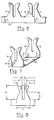
- Figures 5, 6 and 7, illustrate three variations or alternate arrangements of the contact as in Figure 1, and Figures 2 to 4. While in Figure 1, a single contact is illustrated, multiple forms can also be provided.
- Figure 5 illustrates a "back-to-back" arrangement with beams 11 and 12 extending from both sides of a common base 13.
- Figure 6 illustrates a strip arrangement, in which two or more contacts are formed from a long strip having a long base 13.
- Figure 7 illustrates a double contact in which the bases 13 are common with an interconnecting web 30.
- a range of conductor sizes can be accommodated by one particular size of contact, if desired, although contacts can be designed specifically for each conductor size.
- FIG 8 is illustrated a contact, as in Figure 1 and in Figures 2, 3 and 4, for acceptance of 22, 24 and 26 AWG telephone wire conductors.
- the various dimensions indicated, and listed below, are for each conductor but are approximate and can be varied.
- the angle % can vary as can the radii r but the particular dimensions and values given are particularly suitable for telephone conductors, having copper conductors, of the gauges given. All the generally used insulating materials can be stripped, e.g. paper pulp, plastic, foam, foam skin, etc.
- the position of the neck 18 be below the junction of the radius 20 and the inner edges 14, and that the rest point of the conductor 26 is below the neck 18.
- the angle ⁇ and radius r affect the initial insertion force and the force applied to the insulation.
- the slot width f, radius r and dimension (a-b), determine both the amount of deformation of the conductor core and the bending or spreading of the legs 11 and 12, which both also depend upon the conductor size.
- a typical material is phosphor bronze, of about .012" thickness.
- the contact can be used with bare conductors. There may be reduced deformation of the beams, without the insulation, but the same basic situation occurs with deformation of the conductor occurring prior to entry into the slot 15. Similar structures can be used to retain small diameter rods or "wires" of other materials than metal, and it is possible to make the retaining member of non-metallic material, depending upon use.
Landscapes
- Connections By Means Of Piercing Elements, Nuts, Or Screws (AREA)
- Coupling Device And Connection With Printed Circuit (AREA)
Applications Claiming Priority (2)
| Application Number | Priority Date | Filing Date | Title |
|---|---|---|---|
| CA355,309A CA1115796A (en) | 1980-07-03 | 1980-07-03 | Retainer member with dual action cantilever beams |
| CA355309 | 1980-07-03 |
Publications (3)
| Publication Number | Publication Date |
|---|---|
| EP0043437A2 true EP0043437A2 (de) | 1982-01-13 |
| EP0043437A3 EP0043437A3 (en) | 1982-09-29 |
| EP0043437B1 EP0043437B1 (de) | 1985-03-06 |
Family
ID=4117328
Family Applications (1)
| Application Number | Title | Priority Date | Filing Date |
|---|---|---|---|
| EP19810104120 Expired EP0043437B1 (de) | 1980-07-03 | 1981-05-29 | Kontaktglied zur mechanischen Sicherung mit zwei aktiven freitragenden Schenkeln |
Country Status (4)
| Country | Link |
|---|---|
| EP (1) | EP0043437B1 (de) |
| JP (2) | JPS5730274A (de) |
| CA (1) | CA1115796A (de) |
| DE (1) | DE3169168D1 (de) |
Cited By (7)
| Publication number | Priority date | Publication date | Assignee | Title |
|---|---|---|---|---|
| WO1986002497A1 (en) * | 1984-10-17 | 1986-04-24 | Amp Incorporated | Select solder slot termination method and product |
| GB2202998A (en) * | 1987-03-16 | 1988-10-05 | Johnson Electric Ind Mfg | A method of connecting an armature winding to a commutator |
| US4876474A (en) * | 1986-12-11 | 1989-10-24 | Johnson Electric Industrial Manufactory, Limited | Commutator |
| WO1991011832A1 (en) * | 1990-01-31 | 1991-08-08 | N.V. Raychem S.A. | Electrical connector |
| FR2659514A1 (fr) * | 1990-03-07 | 1991-09-13 | Cit Alcatel | Cordon en y pour l'adjonction d'un ecouteur supplementaire a un poste telephonique non prevu pour en comporter un. |
| EP0665614A3 (de) * | 1994-01-31 | 1997-03-05 | Krone Ag | Schneidklemm-Kontaktelement. |
| EP0715371A3 (de) * | 1994-11-29 | 1998-01-21 | Sumitomo Wiring Systems, Ltd. | Elektrische Anschlussdose |
Family Cites Families (7)
| Publication number | Priority date | Publication date | Assignee | Title |
|---|---|---|---|---|
| BE630034A (de) * | 1962-03-26 | |||
| US3521221A (en) * | 1968-02-21 | 1970-07-21 | Northern Electric Co | Insulation slicing connector |
| US4084877A (en) * | 1969-10-22 | 1978-04-18 | The Siemon-Dynamic Mfg. Company | Electrical connectors and terminal connecting block |
| JPS4964884A (de) * | 1972-10-31 | 1974-06-24 | ||
| US4027368A (en) * | 1976-06-22 | 1977-06-07 | Amp Incorporated | Forceps tool for wire insertion |
| US4062614A (en) * | 1976-07-30 | 1977-12-13 | Bell Telephone Laboratories, Incorporated | Insulation piercing slotted beam electrical connector |
| AU525919B2 (en) * | 1979-01-22 | 1982-12-09 | Amp Incorporated | Flat cable connector |
-
1980
- 1980-07-03 CA CA355,309A patent/CA1115796A/en not_active Expired
-
1981
- 1981-05-29 EP EP19810104120 patent/EP0043437B1/de not_active Expired
- 1981-05-29 DE DE8181104120T patent/DE3169168D1/de not_active Expired
- 1981-06-23 JP JP9608681A patent/JPS5730274A/ja active Pending
-
1990
- 1990-03-02 JP JP2054690U patent/JPH0414855Y2/ja not_active Expired
Cited By (10)
| Publication number | Priority date | Publication date | Assignee | Title |
|---|---|---|---|---|
| WO1986002497A1 (en) * | 1984-10-17 | 1986-04-24 | Amp Incorporated | Select solder slot termination method and product |
| US4876474A (en) * | 1986-12-11 | 1989-10-24 | Johnson Electric Industrial Manufactory, Limited | Commutator |
| GB2202998A (en) * | 1987-03-16 | 1988-10-05 | Johnson Electric Ind Mfg | A method of connecting an armature winding to a commutator |
| WO1991011832A1 (en) * | 1990-01-31 | 1991-08-08 | N.V. Raychem S.A. | Electrical connector |
| US5482467A (en) * | 1990-01-31 | 1996-01-09 | N.V. Raychem S.A. | Electrical connector |
| FR2659514A1 (fr) * | 1990-03-07 | 1991-09-13 | Cit Alcatel | Cordon en y pour l'adjonction d'un ecouteur supplementaire a un poste telephonique non prevu pour en comporter un. |
| EP0665614A3 (de) * | 1994-01-31 | 1997-03-05 | Krone Ag | Schneidklemm-Kontaktelement. |
| US5685733A (en) * | 1994-01-31 | 1997-11-11 | Krone Aktiengesellschaft | Insulation displacement contact element |
| EP0715371A3 (de) * | 1994-11-29 | 1998-01-21 | Sumitomo Wiring Systems, Ltd. | Elektrische Anschlussdose |
| US5797763A (en) * | 1994-11-29 | 1998-08-25 | Sumitomo Wiring Systems, Ltd. | Electrical connection box |
Also Published As
| Publication number | Publication date |
|---|---|
| JPS5730274A (en) | 1982-02-18 |
| JPH0414855Y2 (de) | 1992-04-03 |
| DE3169168D1 (en) | 1985-04-11 |
| CA1115796A (en) | 1982-01-05 |
| JPH0355662U (de) | 1991-05-29 |
| EP0043437A3 (en) | 1982-09-29 |
| EP0043437B1 (de) | 1985-03-06 |
Similar Documents
| Publication | Publication Date | Title |
|---|---|---|
| US4682835A (en) | Insulation displacing terminal with cantilever spring contact members | |
| US4261629A (en) | Slotted plate terminal | |
| US4806120A (en) | Electrical terminal | |
| US4035049A (en) | Universal solderless termination system | |
| US4333700A (en) | Insulation-penetrating slotted beam contact element | |
| US4141618A (en) | Transversely slotted barrel terminal | |
| US4442316A (en) | Crimp connector for electrical wires | |
| CA1286741C (en) | Cutting/clamping sleeve contact | |
| US4050760A (en) | Solderless electrical contact | |
| US4310212A (en) | Retainer member with dual action cantilever beams | |
| JPH0744046B2 (ja) | 絶縁穿孔導電端子 | |
| GB2037493A (en) | Insulation displacing contact for electrical connector | |
| JP3970321B2 (ja) | 電線接続システム | |
| CA1150378A (en) | Slotted plate terminal renewable as spade terminal | |
| EP0043437B1 (de) | Kontaktglied zur mechanischen Sicherung mit zwei aktiven freitragenden Schenkeln | |
| US4264118A (en) | Insulation-pierce and crimp termination and method for effecting same | |
| GB1587453A (en) | Electrical connector | |
| EP0320310B1 (de) | Isolierungsschneidender Anschluss mit hohem Kontaktdruck für mehradrige Kabel | |
| CA1195398A (en) | Terminal for solderless contact | |
| US4919622A (en) | Insulation displacing terminal | |
| AU723780B2 (en) | Connection device for at least two sheathed conductive wires | |
| US4306759A (en) | Insulation-cutting connectors and method of making connections | |
| US4288918A (en) | Method and apparatus for making a crimped, insulation-pierce electrical connection | |
| US5911593A (en) | Electrical conductor terminal and a method of connecting an electrical conductor to a terminal | |
| US4414740A (en) | Insulation-pierce and crimp termination tool |
Legal Events
| Date | Code | Title | Description |
|---|---|---|---|
| PUAI | Public reference made under article 153(3) epc to a published international application that has entered the european phase |
Free format text: ORIGINAL CODE: 0009012 |
|
| AK | Designated contracting states |
Designated state(s): DE GB NL SE |
|
| 17P | Request for examination filed |
Effective date: 19811210 |
|
| PUAL | Search report despatched |
Free format text: ORIGINAL CODE: 0009013 |
|
| AK | Designated contracting states |
Designated state(s): DE GB NL SE |
|
| GRAA | (expected) grant |
Free format text: ORIGINAL CODE: 0009210 |
|
| AK | Designated contracting states |
Designated state(s): DE GB NL SE |
|
| REF | Corresponds to: |
Ref document number: 3169168 Country of ref document: DE Date of ref document: 19850411 |
|
| PLBE | No opposition filed within time limit |
Free format text: ORIGINAL CODE: 0009261 |
|
| STAA | Information on the status of an ep patent application or granted ep patent |
Free format text: STATUS: NO OPPOSITION FILED WITHIN TIME LIMIT |
|
| 26N | No opposition filed | ||
| PGFP | Annual fee paid to national office [announced via postgrant information from national office to epo] |
Ref country code: SE Payment date: 19920421 Year of fee payment: 12 |
|
| PGFP | Annual fee paid to national office [announced via postgrant information from national office to epo] |
Ref country code: NL Payment date: 19920531 Year of fee payment: 12 |
|
| PGFP | Annual fee paid to national office [announced via postgrant information from national office to epo] |
Ref country code: GB Payment date: 19930518 Year of fee payment: 13 |
|
| PG25 | Lapsed in a contracting state [announced via postgrant information from national office to epo] |
Ref country code: SE Effective date: 19930530 |
|
| PGFP | Annual fee paid to national office [announced via postgrant information from national office to epo] |
Ref country code: DE Payment date: 19930713 Year of fee payment: 13 |
|
| PG25 | Lapsed in a contracting state [announced via postgrant information from national office to epo] |
Ref country code: NL Effective date: 19931201 |
|
| NLV4 | Nl: lapsed or anulled due to non-payment of the annual fee | ||
| PG25 | Lapsed in a contracting state [announced via postgrant information from national office to epo] |
Ref country code: GB Effective date: 19940529 |
|
| GBPC | Gb: european patent ceased through non-payment of renewal fee |
Effective date: 19940529 |
|
| EUG | Se: european patent has lapsed |
Ref document number: 81104120.1 Effective date: 19931210 |
|
| PG25 | Lapsed in a contracting state [announced via postgrant information from national office to epo] |
Ref country code: DE Effective date: 19950201 |