EP0043452A2 - Dispositif de réglage pour compresseurs axiaux - Google Patents
Dispositif de réglage pour compresseurs axiaux Download PDFInfo
- Publication number
- EP0043452A2 EP0043452A2 EP81104342A EP81104342A EP0043452A2 EP 0043452 A2 EP0043452 A2 EP 0043452A2 EP 81104342 A EP81104342 A EP 81104342A EP 81104342 A EP81104342 A EP 81104342A EP 0043452 A2 EP0043452 A2 EP 0043452A2
- Authority
- EP
- European Patent Office
- Prior art keywords
- blades
- row
- guide
- blade
- guide vanes
- Prior art date
- Legal status (The legal status is an assumption and is not a legal conclusion. Google has not performed a legal analysis and makes no representation as to the accuracy of the status listed.)
- Granted
Links
Images



Classifications
-
- F—MECHANICAL ENGINEERING; LIGHTING; HEATING; WEAPONS; BLASTING
- F01—MACHINES OR ENGINES IN GENERAL; ENGINE PLANTS IN GENERAL; STEAM ENGINES
- F01D—NON-POSITIVE DISPLACEMENT MACHINES OR ENGINES, e.g. STEAM TURBINES
- F01D5/00—Blades; Blade-carrying members; Heating, heat-insulating, cooling or antivibration means on the blades or the members
- F01D5/12—Blades
- F01D5/14—Form or construction
- F01D5/141—Shape, i.e. outer, aerodynamic form
- F01D5/146—Shape, i.e. outer, aerodynamic form of blades with tandem configuration, split blades or slotted blades
-
- F—MECHANICAL ENGINEERING; LIGHTING; HEATING; WEAPONS; BLASTING
- F01—MACHINES OR ENGINES IN GENERAL; ENGINE PLANTS IN GENERAL; STEAM ENGINES
- F01D—NON-POSITIVE DISPLACEMENT MACHINES OR ENGINES, e.g. STEAM TURBINES
- F01D17/00—Regulating or controlling by varying flow
- F01D17/10—Final actuators
- F01D17/12—Final actuators arranged in stator parts
- F01D17/14—Final actuators arranged in stator parts varying effective cross-sectional area of nozzles or guide conduits
- F01D17/16—Final actuators arranged in stator parts varying effective cross-sectional area of nozzles or guide conduits by means of nozzle vanes
- F01D17/162—Final actuators arranged in stator parts varying effective cross-sectional area of nozzles or guide conduits by means of nozzle vanes for axial flow, i.e. the vanes turning around axes which are essentially perpendicular to the rotor centre line
-
- F—MECHANICAL ENGINEERING; LIGHTING; HEATING; WEAPONS; BLASTING
- F04—POSITIVE - DISPLACEMENT MACHINES FOR LIQUIDS; PUMPS FOR LIQUIDS OR ELASTIC FLUIDS
- F04D—NON-POSITIVE-DISPLACEMENT PUMPS
- F04D27/00—Control, e.g. regulation, of pumps, pumping installations or pumping systems specially adapted for elastic fluids
- F04D27/02—Surge control
- F04D27/0246—Surge control by varying geometry within the pumps, e.g. by adjusting vanes
-
- F—MECHANICAL ENGINEERING; LIGHTING; HEATING; WEAPONS; BLASTING
- F04—POSITIVE - DISPLACEMENT MACHINES FOR LIQUIDS; PUMPS FOR LIQUIDS OR ELASTIC FLUIDS
- F04D—NON-POSITIVE-DISPLACEMENT PUMPS
- F04D29/00—Details, component parts, or accessories
- F04D29/40—Casings; Connections of working fluid
- F04D29/52—Casings; Connections of working fluid for axial pumps
- F04D29/54—Fluid-guiding means, e.g. diffusers
- F04D29/56—Fluid-guiding means, e.g. diffusers adjustable
- F04D29/563—Fluid-guiding means, e.g. diffusers adjustable specially adapted for elastic fluid pumps
-
- Y—GENERAL TAGGING OF NEW TECHNOLOGICAL DEVELOPMENTS; GENERAL TAGGING OF CROSS-SECTIONAL TECHNOLOGIES SPANNING OVER SEVERAL SECTIONS OF THE IPC; TECHNICAL SUBJECTS COVERED BY FORMER USPC CROSS-REFERENCE ART COLLECTIONS [XRACs] AND DIGESTS
- Y02—TECHNOLOGIES OR APPLICATIONS FOR MITIGATION OR ADAPTATION AGAINST CLIMATE CHANGE
- Y02T—CLIMATE CHANGE MITIGATION TECHNOLOGIES RELATED TO TRANSPORTATION
- Y02T50/00—Aeronautics or air transport
- Y02T50/60—Efficient propulsion technologies, e.g. for aircraft
Definitions
- the invention relates to a device for regulating axial compressors by adjusting two guide vanes one behind the other in the flow direction with guide vanes set in their neutral position (blade position at 0 ° deviation from the direction of the rotor axis) parallel to the rotor axis, in each case rotatable about a blade axis of rotation, the guide vanes the front (first) guide vane row in the flow direction can be adjusted with a leading setting angle with the aid of an adjusting ring or the like with respect to the guide vanes of the (second) guide vane row following in the flow direction, and the respective setting angle of the vanes of the one guide vane row has a relationship to this angle that is in a certain ratio Setting angle of the blades of the other guide blade row is assigned.
- the entry level plays a special role in the control of axial compressors by adjusting the guide vanes. While the direction of flow to guide vanes between two impellers is already changed by regulating the preceding stages, it remains constant axial for the inlet guide wheel. From a certain angle of adjustment, the flow in the inlet guide wheel is cut off, the following impeller is also affected in its operation. A calculation of the additional losses in the inlet stator and in the first impeller clearly shows that after a stall in the inlet stator a positive control effect in the counter-swirl direction no longer occurs, in the partial load range there is a control gap in which the flow deflection is smaller than before the stall, the efficiency of the first Stage is severely affected and the blades are exposed to fluctuating forces.
- the inflow speed to the blades of the inlet stator is always essentially axially directed.
- the blades of the inlet guide wheel are adjusted by adjusting the guide vanes, they must always divert the flow from the axial direction into another direction, partly in the direction of the rotation of the compressor rotor (co-rotation) and partly in the opposite direction (counter-swirl).
- the flow to the profile stops when a certain angle of attack is exceeded.
- the invention provides a very simple construction, apart from the fact that a tandem wheel is advantageously used. Thanks to the arrangement of the guide vanes, the gap effect can be optimized in the two end positions, while the gap between these end positions is still effective, even if it is not optimal.
- the device according to the invention achieved a significantly improved control behavior in the part-load range and in the upper-load range.
- the control effectiveness of the inlet guide wheel has increased while avoiding or delaying the stall.
- the efficiency has increased;
- by avoiding or delaying the stall it has become possible to expand the overload range, while detached flow reverses the control efficiency in the inlet impellers and this phenomenon could only be avoided if the very complicated designs mentioned were used.
- the construction of the adjusting ring is considerably simplified and has the advantage that the angle assignment by which the rows of blades are rotated can be determined by the length of the levers.
- the guide blades of the first blade row I are designated 1 and 1 '. They are arranged rotatably about the axis of rotation 3 or 3 '.
- the arrangement of the guide blades 2, 2 'with the axes of rotation 4 and 4' is analogous to the arrangement of the first blade row I.
- 0 is the neutral position, the chords of the blade profiles lying in the direction of flow;
- a and B denote the swirl positions ("positive" swirl and "negative” swirl).
- the adjustment angle of the blade row II are initially greater than the angle of the blade row I.
- the respective setting angle of the guide vanes of the row I is assigned a certain relation to this angle to the setting angle of the guide blades of the blade row II. This ratio is given by the construction of the adjusting ring, as will be explained in more detail later.
- chord lengths of the blades 1 and 1 ' are equal to the chord lengths of the blades 2 and 2'.
- the chord lengths can also be different.
- a guide blade 2 or 2 'of the second row II is arranged between two adjacent guide blades 1, 1' of the first blade row I.
- the distance between the guide vane centers 3 and 4 of the two guide vane rows I and II in the direction of the rotor axis and the distance between two adjacent guide vane centers 1, 1 '; 2, 2 'of a blade row I or II and the chord lengths of the guide blades 1, 2 are coordinated with one another in such a way that when the guide blades are set to produce a desired, respectively maximum deflection angle in both control senses, i.e.
- a blade 1 of the first blade row 1 interacts with an adjacent blade 2 or 2 'of the second blade row II. It is essential that an effective gap remains between the respective interacting guide vanes 1 and 2 or 2 ', so that an optimal flow is created.
- the guide vanes are arranged such that - viewed perpendicular to the direction of the rotor axis - in position "A" the nose area 2a of the guide vane 2 overlaps with the trailing edge area lb of the adjacent guide vane 1 of the first vane row I.
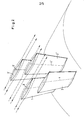
- FIG. 3 A part of the guide vane ring with blades 1, 2 and 1 '2' set to "positive" swirl is also shown in perspective in FIG. 3.
- Fig. 2 shows a part of the guide vane ring with blades set in the neutral position (see FIG. 1, position "0").
- the tendons of the blades 1, 2; 1 ', 2' to each other and to the rotor axis parallel.
- the flow through the blades is essentially parallel to the rotor axis.
- FIG. 4 shows a perspective view of the blades 1, 2 'set to "negative” twist (see FIG. 1, position “B”); 1 ", 2 with indicated flow lines. In this position, viewed in the direction perpendicular to the rotor axis, the rear edge area of the blade 1" or 1 overlaps with the nose area of the blade 2 or 2 '.
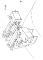
- the guide vane adjustment mechanism is explained below with reference to FIG. 5. In the position shown, the blades 1, 2; 1 ', 2' in neutral position.
- the blades are each firmly connected via shafts 9 (blades 1 and 1 ') or 8 (blade 2) with levers 7 (7') or 6 (6 ').
- the shafts 8 and 9 are articulated in a housing, not shown.
- the blades are adjusted via an adjusting ring 5, which is partially shown.
- the levers 6 and 7 are supported in the adjusting ring 5 by means of shafts 10 and 11, respectively.
- oval openings 12 which extend in the direction of the rotor axis, are provided on the adjusting ring 5.
Landscapes
- Engineering & Computer Science (AREA)
- Mechanical Engineering (AREA)
- General Engineering & Computer Science (AREA)
- Physics & Mathematics (AREA)
- Fluid Mechanics (AREA)
- Geometry (AREA)
- Structures Of Non-Positive Displacement Pumps (AREA)
- Control Of Positive-Displacement Air Blowers (AREA)
Applications Claiming Priority (2)
| Application Number | Priority Date | Filing Date | Title |
|---|---|---|---|
| DE19803025753 DE3025753A1 (de) | 1980-07-08 | 1980-07-08 | Vorrichtung zur regelung von axialverdichtern |
| DE3025753 | 1980-07-08 |
Publications (3)
| Publication Number | Publication Date |
|---|---|
| EP0043452A2 true EP0043452A2 (fr) | 1982-01-13 |
| EP0043452A3 EP0043452A3 (en) | 1982-05-12 |
| EP0043452B1 EP0043452B1 (fr) | 1984-10-10 |
Family
ID=6106629
Family Applications (1)
| Application Number | Title | Priority Date | Filing Date |
|---|---|---|---|
| EP81104342A Expired EP0043452B1 (fr) | 1980-07-08 | 1981-06-05 | Dispositif de réglage pour compresseurs axiaux |
Country Status (4)
| Country | Link |
|---|---|
| US (1) | US4558987A (fr) |
| EP (1) | EP0043452B1 (fr) |
| JP (1) | JPS5751998A (fr) |
| DE (1) | DE3025753A1 (fr) |
Cited By (6)
| Publication number | Priority date | Publication date | Assignee | Title |
|---|---|---|---|---|
| DE3618331A1 (de) * | 1985-06-03 | 1986-12-04 | General Electric Co., Schenectady, N.Y. | Betaetigungshebel fuer ein paar verstellbare leitschaufeln |
| US20140044518A1 (en) * | 2012-08-09 | 2014-02-13 | MTU Aero Engines AG | Continuous-flow machine with at least one guide vane ring |
| FR3025564A1 (fr) * | 2014-09-04 | 2016-03-11 | Snecma | Systeme d'aubes a calage variable pour une turbomachine |
| EP3009598A1 (fr) * | 2014-10-16 | 2016-04-20 | United Technologies Corporation | Pales de rotor en tandem |
| EP3686396A1 (fr) * | 2019-01-24 | 2020-07-29 | MTU Aero Engines GmbH | Grille d'aube de guidage pour une turbomachine |
| US20220381153A1 (en) * | 2019-12-18 | 2022-12-01 | Safran Aircraft Engines | Compressor module for turbomachine |
Families Citing this family (23)
| Publication number | Priority date | Publication date | Assignee | Title |
|---|---|---|---|---|
| JPS6140094A (ja) * | 1984-07-31 | 1986-02-26 | 新神戸電機株式会社 | 多層積層板の製造法 |
| JPS61174796A (ja) * | 1985-01-30 | 1986-08-06 | 新神戸電機株式会社 | 多層回路板の製造法 |
| DE3624951C1 (en) * | 1986-02-28 | 1987-10-29 | Mtu Muenchen Gmbh | Turbocompressor with variable geometry |
| FR2595117B1 (fr) * | 1986-02-28 | 1991-05-17 | Mtu Muenchen Gmbh | Turbocompresseur a geometrie variable |
| JP2954539B2 (ja) * | 1996-08-09 | 1999-09-27 | 川崎重工業株式会社 | タンデム翼列 |
| US6039534A (en) * | 1998-09-21 | 2000-03-21 | Northern Research And Engineering Corp | Inlet guide vane assembly |
| GB0002257D0 (en) * | 2000-02-02 | 2000-03-22 | Rolls Royce Plc | Rotary apparatus for a gas turbine engine |
| TW546443B (en) * | 2002-09-27 | 2003-08-11 | Delta Electronics Inc | Axial flow fan with a plurality of segment blades |
| GB2420157B (en) * | 2003-05-14 | 2006-06-28 | Rolls Royce Plc | A stator vane assembly for a turbomachine |
| DE10329281A1 (de) * | 2003-06-30 | 2005-01-20 | Daimlerchrysler Ag | Verdichter im Ansaugtrakt einer Brennkraftmaschine |
| FR2858027B1 (fr) * | 2003-07-21 | 2005-09-23 | Snecma Moteurs | Compresseur haute pression a cycle hybride et turbomachine comprenant un tel compresseur |
| GB2405184A (en) * | 2003-08-22 | 2005-02-23 | Rolls Royce Plc | A gas turbine engine lift fan with tandem inlet guide vanes |
| FR2880078B1 (fr) * | 2004-12-23 | 2007-02-02 | Renault Sas | Conduit d'admission a la roue du compresseur d'un turbocompresseur |
| JP5644302B2 (ja) * | 2010-09-15 | 2014-12-24 | 株式会社Ihi | 軸流圧縮機及びガスタービンエンジン |
| US20140130513A1 (en) * | 2012-11-09 | 2014-05-15 | General Electric Company | System and method for improving gas turbine performance at part-load operation |
| CN102979658A (zh) * | 2012-12-06 | 2013-03-20 | 中国水利水电科学研究院 | 双活动导叶水泵水轮机 |
| CN103511344A (zh) * | 2013-09-23 | 2014-01-15 | 哈尔滨汽轮机厂有限责任公司 | 一种燃气轮机用压气机的高压中间级导叶片 |
| TWI614410B (zh) | 2013-12-17 | 2018-02-11 | 財團法人工業技術研究院 | 進氣導葉組件 |
| US10233782B2 (en) * | 2016-08-03 | 2019-03-19 | Solar Turbines Incorporated | Turbine assembly and method for flow control |
| US10883379B2 (en) * | 2018-05-11 | 2021-01-05 | Rolls-Royce Corporation | Variable diffuser having a respective penny for each vane |
| US20200248560A1 (en) * | 2019-02-05 | 2020-08-06 | United Technologies Corporation | Tandem fan for boundary layer ingestion systems |
| CN114165477B (zh) * | 2021-12-13 | 2023-02-03 | 北京理工大学 | 一种轴向超音通流风扇串列构型及串列构型优化方法 |
| CN114542515B (zh) * | 2022-03-08 | 2024-05-03 | 大连海事大学 | 一种串联进口可调导叶机构 |
Family Cites Families (10)
| Publication number | Priority date | Publication date | Assignee | Title |
|---|---|---|---|---|
| US2733853A (en) * | 1956-02-07 | trumpler | ||
| US1462483A (en) * | 1921-09-21 | 1923-07-24 | Worthington Pump & Mach Corp | Hydraulic turbine |
| US2933234A (en) * | 1954-12-28 | 1960-04-19 | Gen Electric | Compressor stator assembly |
| AT253664B (de) * | 1965-04-15 | 1967-04-25 | Simmering Graz Pauker Ag | Eintrittsleitapparat für Gebläse |
| DE1503647A1 (de) * | 1965-06-19 | 1969-03-13 | Meissen Turbowerke | Spaltfluegelrad fuer axiale Stroemungsmaschinen,insbesondere fuer Luefter und Geblaese |
| CH486636A (de) * | 1968-08-20 | 1970-02-28 | Escher Wyss Ag | Diffusor einer Zentrifugalfördermaschine |
| FR2123831A5 (fr) * | 1971-02-02 | 1972-09-15 | Edf | |
| DE2403113C3 (de) * | 1974-01-23 | 1979-04-19 | Gutehoffnungshuette Sterkrade Ag, 4200 Oberhausen | Vorrichtung zum Verstellen der Drallschaufeln eines Turboverdichters |
| DE2502986C2 (de) * | 1975-01-25 | 1985-04-11 | M.A.N. Maschinenfabrik Augsburg-Nürnberg AG, 4200 Oberhausen | Vorrichtung zum Verstellen der Drallschaufeln eines Turboverdichters |
| US4295784A (en) * | 1979-09-26 | 1981-10-20 | United Technologies Corporation | Variable stator |
-
1980
- 1980-07-08 DE DE19803025753 patent/DE3025753A1/de not_active Ceased
-
1981
- 1981-06-05 EP EP81104342A patent/EP0043452B1/fr not_active Expired
- 1981-07-07 JP JP56105150A patent/JPS5751998A/ja active Pending
-
1985
- 1985-04-05 US US06/720,051 patent/US4558987A/en not_active Expired - Fee Related
Cited By (12)
| Publication number | Priority date | Publication date | Assignee | Title |
|---|---|---|---|---|
| DE3618331A1 (de) * | 1985-06-03 | 1986-12-04 | General Electric Co., Schenectady, N.Y. | Betaetigungshebel fuer ein paar verstellbare leitschaufeln |
| FR2582729A1 (fr) * | 1985-06-03 | 1986-12-05 | Gen Electric | Levier de manoeuvre pour aubes de stators variables |
| US20140044518A1 (en) * | 2012-08-09 | 2014-02-13 | MTU Aero Engines AG | Continuous-flow machine with at least one guide vane ring |
| US9506360B2 (en) * | 2012-08-09 | 2016-11-29 | MTU Aero Engines AG | Continuous-flow machine with at least one guide vane ring |
| FR3025564A1 (fr) * | 2014-09-04 | 2016-03-11 | Snecma | Systeme d'aubes a calage variable pour une turbomachine |
| EP3009598A1 (fr) * | 2014-10-16 | 2016-04-20 | United Technologies Corporation | Pales de rotor en tandem |
| US10598024B2 (en) | 2014-10-16 | 2020-03-24 | United Technologies Corporation | Tandem rotor blades |
| US11852034B2 (en) | 2014-10-16 | 2023-12-26 | Rtx Corporation | Tandem rotor blades |
| EP3686396A1 (fr) * | 2019-01-24 | 2020-07-29 | MTU Aero Engines GmbH | Grille d'aube de guidage pour une turbomachine |
| US11280212B2 (en) | 2019-01-24 | 2022-03-22 | MTU Aero Engines AG | Guide vane cascade for a turbomachine |
| US20220381153A1 (en) * | 2019-12-18 | 2022-12-01 | Safran Aircraft Engines | Compressor module for turbomachine |
| US11661860B2 (en) * | 2019-12-18 | 2023-05-30 | Safran Aircraft Engines | Compressor module for turbomachine |
Also Published As
| Publication number | Publication date |
|---|---|
| DE3025753A1 (de) | 1982-01-28 |
| JPS5751998A (en) | 1982-03-27 |
| US4558987A (en) | 1985-12-17 |
| EP0043452A3 (en) | 1982-05-12 |
| EP0043452B1 (fr) | 1984-10-10 |
Similar Documents
| Publication | Publication Date | Title |
|---|---|---|
| EP0043452B1 (fr) | Dispositif de réglage pour compresseurs axiaux | |
| DE1528824C3 (de) | Axial wirkende Flüssigkeits-Strömungsmaschine mit umkehrbarer Arbeitsrichtung | |
| DE69820853T2 (de) | Axiallüfter | |
| DE69711793T2 (de) | Schaufel für axiale Strömungsmaschine | |
| DE3882463T2 (de) | Diffusor für Zentrifugalverdichter. | |
| DE69926236T2 (de) | Gasturbinenelement | |
| DE3127214C2 (de) | Diffusor für einen Überschallzentrifugalverdichter | |
| EP0126399B1 (fr) | Conduit de fluide présentant une construction réduite | |
| EP2947270B1 (fr) | Groupe de série d'aubes | |
| CH684354A5 (de) | Radialverdichter. | |
| EP0985098B1 (fr) | Pompe centrifuge a dispositif de guidage d'admission | |
| DE2712306A1 (de) | Universal-laufradrohling fuer turboverdichter und verfahren zu seiner herstellung | |
| EP1948939B1 (fr) | Roue mobile de compresseur radial | |
| EP1244872B1 (fr) | Pale de rotor pour eolienne | |
| DE112022006404T5 (de) | Mischstromturbine und turbolader | |
| EP0131719A2 (fr) | Dispositif variable de guidage | |
| EP2568166B1 (fr) | Pale de rotor d'éolienne dotée d'un rebord arrière à profil épais | |
| WO1995025895A1 (fr) | Dispositif pour reduire le bruit de pompes centrifuges | |
| DE2050950A1 (de) | Uberschallkompressor mit konischem Einlauf | |
| DE3424010A1 (de) | Schraube fuer gasfoermige oder fluessige medien, insbesondere luftschraube | |
| WO1980000733A1 (fr) | Moteur a vent | |
| DE2203353C3 (de) | Lufter, insbesondere fur Brennkraftmaschinen | |
| WO1996001368A1 (fr) | Convertisseur d'energie eolienne a axe de rotation vertical | |
| DE102004038639A1 (de) | Francis Turbine | |
| DE3222164A1 (de) | Z.b. in verbindung mit klimaanlagen zu verwendende geblaeseanordnung und mit einer solchen geblaeseanordnung ausgeruestete klimaanlage |
Legal Events
| Date | Code | Title | Description |
|---|---|---|---|
| PUAI | Public reference made under article 153(3) epc to a published international application that has entered the european phase |
Free format text: ORIGINAL CODE: 0009012 |
|
| AK | Designated contracting states |
Designated state(s): CH FR GB IT SE |
|
| ITCL | It: translation for ep claims filed |
Representative=s name: MODIANO & ASSOCIATI S.R.L. |
|
| PUAL | Search report despatched |
Free format text: ORIGINAL CODE: 0009013 |
|
| AK | Designated contracting states |
Designated state(s): CH FR GB IT SE |
|
| 17P | Request for examination filed |
Effective date: 19820708 |
|
| ITF | It: translation for a ep patent filed | ||
| GRAA | (expected) grant |
Free format text: ORIGINAL CODE: 0009210 |
|
| AK | Designated contracting states |
Designated state(s): CH FR GB IT LI SE |
|
| ET | Fr: translation filed | ||
| PLBI | Opposition filed |
Free format text: ORIGINAL CODE: 0009260 |
|
| 26 | Opposition filed |
Opponent name: M.A.N. MASCHINENFABRIK AUGSBURG-NUERNBERG AKTIENGE Effective date: 19850702 |
|
| PLAB | Opposition data, opponent's data or that of the opponent's representative modified |
Free format text: ORIGINAL CODE: 0009299OPPO |
|
| R26 | Opposition filed (corrected) |
Opponent name: MAN GUTEHOFFNUNGSHUETTE GMBH Effective date: 19850702 |
|
| RDAG | Patent revoked |
Free format text: ORIGINAL CODE: 0009271 |
|
| STAA | Information on the status of an ep patent application or granted ep patent |
Free format text: STATUS: PATENT REVOKED |
|
| GBPR | Gb: patent revoked under art. 102 of the ep convention designating the uk as contracting state | ||
| 27W | Patent revoked |
Effective date: 19870411 |
|
| REG | Reference to a national code |
Ref country code: CH Ref legal event code: PL |
|
| REG | Reference to a national code |
Ref country code: FR Ref legal event code: ST |
|
| EUG | Se: european patent has lapsed |
Ref document number: 81104342.1 Effective date: 19880711 |