EP0043832B1 - Procede et appareil d'alimentation en un materiau de charge - Google Patents
Procede et appareil d'alimentation en un materiau de charge Download PDFInfo
- Publication number
- EP0043832B1 EP0043832B1 EP81900377A EP81900377A EP0043832B1 EP 0043832 B1 EP0043832 B1 EP 0043832B1 EP 81900377 A EP81900377 A EP 81900377A EP 81900377 A EP81900377 A EP 81900377A EP 0043832 B1 EP0043832 B1 EP 0043832B1
- Authority
- EP
- European Patent Office
- Prior art keywords
- carriage
- agitator
- hopper
- area
- moving
- Prior art date
- Legal status (The legal status is an assumption and is not a legal conclusion. Google has not performed a legal analysis and makes no representation as to the accuracy of the status listed.)
- Expired
Links
- 239000000463 material Substances 0.000 title claims abstract description 46
- 238000000034 method Methods 0.000 title claims description 7
- 239000011236 particulate material Substances 0.000 claims description 18
- 238000000151 deposition Methods 0.000 claims description 6
- 239000012530 fluid Substances 0.000 claims description 4
- 230000008018 melting Effects 0.000 abstract description 3
- 238000002844 melting Methods 0.000 abstract description 3
- 230000005484 gravity Effects 0.000 abstract description 2
- 230000008021 deposition Effects 0.000 abstract 1
- 239000000155 melt Substances 0.000 description 9
- 239000012768 molten material Substances 0.000 description 8
- 239000006185 dispersion Substances 0.000 description 6
- NJPPVKZQTLUDBO-UHFFFAOYSA-N novaluron Chemical compound C1=C(Cl)C(OC(F)(F)C(OC(F)(F)F)F)=CC=C1NC(=O)NC(=O)C1=C(F)C=CC=C1F NJPPVKZQTLUDBO-UHFFFAOYSA-N 0.000 description 4
- 239000000428 dust Substances 0.000 description 3
- 210000005069 ears Anatomy 0.000 description 2
- 230000000694 effects Effects 0.000 description 2
- 125000006850 spacer group Chemical group 0.000 description 2
- 229910000746 Structural steel Inorganic materials 0.000 description 1
- 230000015572 biosynthetic process Effects 0.000 description 1
- 239000006063 cullet Substances 0.000 description 1
- 230000003111 delayed effect Effects 0.000 description 1
- 238000006073 displacement reaction Methods 0.000 description 1
- 239000011521 glass Substances 0.000 description 1
- 238000010438 heat treatment Methods 0.000 description 1
- 235000000396 iron Nutrition 0.000 description 1
- 238000012423 maintenance Methods 0.000 description 1
- 238000012986 modification Methods 0.000 description 1
- 230000004048 modification Effects 0.000 description 1
- 239000002245 particle Substances 0.000 description 1
- 238000005382 thermal cycling Methods 0.000 description 1
Images


Classifications
-
- C—CHEMISTRY; METALLURGY
- C03—GLASS; MINERAL OR SLAG WOOL
- C03B—MANUFACTURE, SHAPING, OR SUPPLEMENTARY PROCESSES
- C03B3/00—Charging the melting furnaces
Definitions
- the invention relates to an apparatus for depositing particulate material over a desired area according to the preamble of claim 1. Further the invention relates to a method of depositing particulate material over a desired area according to the preamble of claim 16.
- Regions of the batch layer that are too thin 'melt out' expose the molten material and create regions of excessive heat loss with a concomitant lowering of the temperatures of the molten material or melt and a lowering of the melt flow rate.
- regions of thinly covered melt may allow equipment located over the furnace, such as a batch feeder, to be exposed to excessive heat.
- the melt temperature may rise and uncontrollably increase the melt flow rate. Too much batch material also promotes formation of a surface crust which hinders the passage of the overlaying batch material to the melt line.
- the batch feeders disclosed in the prior art do not ensure that a thin, uniform layer of batch material is deposited over the melt.
- Another typical disadvantage is that the feeders require high maintenance.
- An ideal batch feeder would provide a controlled and uniform batch covering, generate little or no dust conditions in the working environment proximate to the furnace, be mechanically simple, inexpensive to construct, operate and maintain and would be highly reliable.
- a further object of the invention is the provision of a method of feeding batch material to an open top electrical furnace in a manner that effectively and efficiently reduces heat loss to the upper surface of the melt.
- the batch distributor or feeder assembly 10 of the present invention may be disposed above an open-top, circular melting furnace (not shown) for melting particulate batch materials such as refractory or glass materials (cullet may also be present) and include a furnace shell from which molten material may be discharged through an outlet member.
- Primary electrodes are positioned radially about an outlet member and are used to melt particulate batch material by the heating effect of current flowing between the primary electrodes and the outlet member to form a pool of molten material.
- the configuration of both the furnace and electrodes may be of the general type illustrated in U.S. Patent No. 3 983 309.
- a batch layer, established on the surface of the molten mass by the batch distributor 10 replenishes the pool of molten material in the furnace as molten material is discharged and also acts as an insulating blanket to insure efficient operation of the furnace.
- the batch distributor 10 embodying the present invention is shown in Fig. 1 and comprises a plurality of drive pedestal subassemblies 12, a main upper drive ring subassembly 14, a distributor support 16 and a distributor 18.
- Each subassembly 12 also provides a means for rotating and counterrotating the main drive ring subassembly 14 about the center of the furnace or the area onto which the particulate material may be deposited.
- Each drive pedestal subassembly 12 comprises a support post or drive pedestal 20 upon which is fixed a mounting plate 22.
- a drive platform 24 is affixed by means of attachment bolts 26 to the plate 22.
- a support frame 28 is slidably mounted upon the platform 24 by means of a pair of adjustable fixable support clamps 30 which cause a lower mounting plate 32 of the frame 28 to slidingly bear against the upper surface of the platform 24.
- each frame 28 Supported by each frame 28 is a motor 34 which is connected via a gear box 36 to a pneumatic tire 38 which abuttingly contacts a main upper drive ring 40 of the main upper drive ring subassembly 14.
- the pneumatic tire 38 contacts the exterior surface of the ring 40 and is driven by the motor 34 such that the ring 40 may be driven either clockwise or counterclockwise.
- the force that the pneumatic tire 38 imposes upon the ring 40 may be controlled by an adjustment means 31.
- Adjustment means 31 comprises a post 33 which is affixed to the lower mounting plate 32 of the frame 28 and a post 35 which is affixed to the upper surface of the platform 24.
- a threaded shaft 37 is rotatably mounted within the post 35 and within the post 33.
- a pair of collars 39 fix the end of the shaft 37 whereupon rotation of the shaft 37 the lower plate 32 of the frame 28 may be displaced relative to the post 35 with a concomitant adjustment of the force that the pneumatic tire 38 imposes upon the ring 40.
- a lock nut 41 fixedly positions the shaft 37 after the desired adjustment has been made.
- the main upper drive ring 40 is suitably supported by means of a plurality of drive ring support wheels 42 which are fixed on shafts 44.
- Each of the two shafts 44 is rotatably supported on a mounting plate 22 by means of a plurality of bearings such as pillow blocks 46 which are suitably attached to the undersurface of each plate 22.
- a bearing 48 fixed within a lower ring 50, that is suitably supported from the undersurface of a platform 24, also provides rotational support for the shafts 44.
- a plurality of collars 52 constrain the longitudinal or lateral movement of each shaft 44 while still permitting rotation of a shaft 44.
- the main upper drive ring assembly 14 also comprises a pair of mounting ears 54 (see FIGS. 1 and 6) which are suitably supported from the lower flange 56 of the ring 40.
- the mounting ears 54 provide a means of supporting the components of the distributor support 16.
- the distributor support 16 comprises a pair of cross members 58 which may be constructed or rectangular tubing.
- a spacer brace 60 insures that the cross members 58 maintain a parallel relationship.
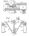
- the particulate batch material receiving distributor 18 Suitably attached to one portion of the distributor support 16 is the particulate batch material receiving distributor 18 which comprises, as shown in FIGS. 1 and 4, a closed, generally V-shaped trough or hopper 62 which is provided with a longitudinal discharge opening 64 and an open top or material intake opening 66.
- the discharge opening has a lineal extent which is substantially equal to the radius of the furnace and is reinforced by means of angle irons 67, which insure that the discharge opening configuration is not deformed by high temperatures experienced proximate the furnace.
- the trough 62 is supported on the cross members 58 via a plurality of transverse angle iron support members 68 and bolts 70 which attach the outer portions of the support members 68 to upper surfaces of the cross members 58.
- the position of the trough 62 relative to the batch layer may be suitably adjusted by means of shims, not shown, which may be inserted between the flanges of the members 68 and the cross members 58.
- the agitator 80 comprises a center post or a stem 82 and a pair of gussets 84 to which are suitably attached a pair of elongated parallel plates 86.
- the plates 86 are fixed apart in a parallel relationship by means of a spacer 88.
- a pair of end caps 92 together with the plates 86 define a material discharge chamber 94 in which is positioned a pair of vertical pins 96 that are fixed at opposite ends of the trough 62 proximate the discharge opening 64.
- the batch material in the trough 62 acting on the outside of the plates 86, tends to restrict the lateral or side-to-side movement of the lower edges of the plates 86. Furthermore, in use, particulate batch material becomes lodged between the outer periphery of the pins 96 and the inner surface of each of the plates 86. Together with the pins 96, the particulate material acts like a hinge to constrain the lateral movement of the lower edges of the plates 86 so that the upper portion of the agitator may be moved by a vibrator (discussed below) and particulate material disposed within the trough 62 may be forced to pass through a plurality of holes or perforations 87 formed in each of the plates 86. In a preferred embodiment, seen in FIG.
- the perforations 87 are disposed in a regular array comprising several rows of perforations.
- the perforations 87 do not extend to the lower edge 89 of the plates 86 in order to substantially seal the bottom of the discharge chamber 94.
- the hole pattern, hole size, number and depth is selected to take advantage of the phenomenon wherein particulate batch material will bridge thereby preventing particulate material from flowing into and through the perforations 87 when the agitator 80 is motionless.
- a vibrator 98 which may be pneumatic or electric, capable of rapidly reciprocating in a single plane, is affixed to a flange 100 of the trough 62 and to a threaded end portion 102 of the stem 82 by means of a bolt 104 and nuts 106, respectively.
- the pneumatic air vibrator 98 is capable of reciprocating up to a maximum amplitude of approximately Y, 6 of an inch (1.6 mm) at a frequency of approximately 3200 vibrations per minute.
- the frequency of vibration should be selected to avoid resonant frequencies of the structure of the feed bar.
- the vibrational frequency should not be so high as to be absorbed by the feed bar structure but should be high enough to cause the feed bar 80 to move through the particulate batch material.
- the optimum vibrational frequency for a particular application appears to be .best determined through trial and error.
- the vibrator 98 moves one end of the feed bar 80 relative to another end, i.e., the end portion 102 relative to the lower edges of the plates 86.
- the vibrator 98 may be supplied with a motive fluid by means of a threaded fitting 108 which releasably attaches a reinforced flexible hose 110.
- the hose 110 is connected to a source of motive fluid (not shown), such as air by means of an elbow fitting 111 (see FIG. 1) fixed on the top flange 116 of the ring 40 and a hose payoff unit or a reel 112 which is fixed relative to the ring 40.
- a source of motive fluid not shown
- the hose 110 is paid off the reel 112 and guided by means of an air hose guide or a channel 114 that is fixed atop the top flange 116.
- the trough 62 is fed with a particulate batch material by means of a system (not shown herein but illustrated in U.S. Patent No. 4,142,880).
- a system (not shown herein but illustrated in U.S. Patent No. 4,142,880).
- Shown in FIG. 2 of that patent is a batch dispersion box held in position above the batch distributor of that patent by a supportarm.
- the batch dispersion box has four sides and a top with an open bottom being disposed such that the batch distributor may be rotated into a loading position where the open top of the distribution trough of the batch distributor is directly below the dispersion box and aligned with an opening in the box.
- a mechanically activated limit switch shown in FIG. 3 of that patent is affixed to a portion of a support frame which is below and radially in alignment with the dispersion box.
- a limit switch actuator depends upwardly from a right angle drive so as to engage the limit switch when the trough has been revolved to a loading position.
- a non-contact level sensor is preferably located along the length of the dispersion box and is responsive to the level of batch material within the trough.
- a hopper, holding a reservoir of batch material, is located above a metering unit to which it delivers batch material by way of a valve. The valve will automatically deliver a quantity of batch material to the holding chamber of the metering unit equal to an amount sufficient for filling the distribution trough.
- a high pressure air blast periodically delivered to the air-tight chamber of the metering unit, will propel its charge of batch material through a conduit as a plug of material in the manner known as dense phase conveying.
- the conduit connects with the interior of the dispersion box through a discharge pipe which directs material downwardly towards the trough. Any excess dust is returned by another conduit through a dust collector, which in turn redelivers the collected material to the metering unit.
- the pneumatic tire 38 is rotated causing the main upper drive ring 40 to rotate in one direction.
- the pneumatic vibrator 98 is actuated and causes the upper portion of the stem 82 to reciprocate back and forth through a relatively small displacement (e.g., less than Y16 inch (1.6 mm)).
- the frequency and amplitude of movement of the vibrator 98 as well as the perforation size, perforation distribution and depth are the variables controlling the mass flow rate of the batch material through the chamber 94.
- the size of the particles of the batch material is an important factor used in determining the perforation parameters.
- the batch material in the trough on the outside of the plates 86 tends to constrain the lateral movement of the lower edges of these plates 86.
- some particulate material becomes lodged in the clearance defined between the pins 96 and the inner surface of each of the plates 86.
- the pins 96 in combination with this particulate material, function as a hinge which tends to restrict the lateral movement (left to right, right to left movement as viewed in FIG. 4) of the lower edges of the plates 86.
- the vibrating feed bar or agitator 80 is caused to be moved back and forth through the particulate material disposed in the trough 62 by the reciprocating arm of the vibrator 98 (note double arrows in FIG. 4).
- the agitator 80 is forced to move back and forth through the material, the material is urged through the perforations 87 and directed into the material discharge chamber 94.
- the particulate material falls by means of gravity through the discharge opening 64 and onto the batch layer as a well-defined sheet of particulate batch material.
- a limit switch 122 (see FIG. 1), fixed relative to the rotatable ring 40, stops the motion of the pneumatic tire causing the entire assembly to come to rest and deactivates the vibrator 98.
- the batch feeder of the present invention will make one revolution of the furnace after which the trough 62 will be delayed at its loading position at the limit switch 122 for a number of seconds which time period allows for any necessary recharging of the trough 62 and a sensing of the batch layer thickness.
- the depositing action will be automatically resumed and the upper ring rotated in a direction opposite to the original direction when the heat sensors indicate the need for a continued distribution of batch material.
- a controlled layer of batch may be uniformly and reliably deposited over the melt of an electric furnace.
- the apparatus could be translated in a linear fashion over a rectangular shaped furnace.
- two diametrically opposed troughs could be provided with motion limited (in the case of a circular furnace) to 180° of rotation.
- the troughs could be filled from a single location allowing the system to rotate back and forth through the desired 180°.
- a single trough, extending diametrically across a circular furnace could be utilized.
Landscapes
- Chemical & Material Sciences (AREA)
- Engineering & Computer Science (AREA)
- Materials Engineering (AREA)
- Organic Chemistry (AREA)
- Feeding, Discharge, Calcimining, Fusing, And Gas-Generation Devices (AREA)
- Filling Or Emptying Of Bunkers, Hoppers, And Tanks (AREA)
- Auxiliary Methods And Devices For Loading And Unloading (AREA)
- Glass Melting And Manufacturing (AREA)
Abstract
Claims (17)
Applications Claiming Priority (2)
| Application Number | Priority Date | Filing Date | Title |
|---|---|---|---|
| US06/112,017 US4285713A (en) | 1980-01-14 | 1980-01-14 | Method and apparatus for feeding batch material |
| US112017 | 1980-01-14 |
Publications (3)
| Publication Number | Publication Date |
|---|---|
| EP0043832A1 EP0043832A1 (fr) | 1982-01-20 |
| EP0043832A4 EP0043832A4 (fr) | 1982-04-29 |
| EP0043832B1 true EP0043832B1 (fr) | 1985-03-20 |
Family
ID=22341694
Family Applications (1)
| Application Number | Title | Priority Date | Filing Date |
|---|---|---|---|
| EP81900377A Expired EP0043832B1 (fr) | 1980-01-14 | 1980-12-22 | Procede et appareil d'alimentation en un materiau de charge |
Country Status (9)
| Country | Link |
|---|---|
| US (1) | US4285713A (fr) |
| EP (1) | EP0043832B1 (fr) |
| JP (1) | JPS57500064A (fr) |
| BE (1) | BE887048A (fr) |
| CA (1) | CA1154485A (fr) |
| DE (1) | DE3070366D1 (fr) |
| FI (1) | FI67834C (fr) |
| IT (1) | IT1142215B (fr) |
| WO (1) | WO1981002007A1 (fr) |
Families Citing this family (11)
| Publication number | Priority date | Publication date | Assignee | Title |
|---|---|---|---|---|
| US4418816A (en) * | 1981-10-19 | 1983-12-06 | Lev Kropp | Inertial conveyor |
| US4954034A (en) * | 1984-10-05 | 1990-09-04 | Zurn Industries, Inc. | Vibratory fuel feeder for furnaces |
| GB2265618A (en) * | 1992-03-30 | 1993-10-06 | Pilkington Glass Ltd | Glass melting |
| US5558691A (en) * | 1994-09-13 | 1996-09-24 | Merkle Engineers, Inc. | Cullet feeder |
| JPH11500400A (ja) | 1994-10-12 | 1999-01-12 | オウェンス コーニング | ガラス繊維ブッシュのセグメントの加熱及び冷却制御方法及び装置 |
| SI9600236B (sl) * | 1996-07-24 | 2004-06-30 | TERMO d.d.,industrija termi�nih izolacij, �kofja Loka | Postopek in naprava za vračanje odpada v kupolne peči |
| DE19755890A1 (de) * | 1997-12-05 | 1999-06-17 | Mannesmann Ag | Beschickungseinrichtung für Schachtöfen |
| CN1907825B (zh) * | 2006-08-23 | 2011-02-16 | 长沙通发高新技术开发有限公司 | 带回转中心支承装置的回转布料机 |
| KR101516480B1 (ko) | 2013-08-16 | 2015-05-04 | 주식회사 엘지실트론 | 폴리 실리콘 충진장치 |
| CN109794734B (zh) * | 2019-01-23 | 2020-03-31 | 武汉船用机械有限责任公司 | 环梁的加工方法 |
| CN114588842B (zh) * | 2022-03-01 | 2022-11-04 | 广东智子智能技术有限公司 | 一种固体物料添加反应釜 |
Family Cites Families (5)
| Publication number | Priority date | Publication date | Assignee | Title |
|---|---|---|---|---|
| US3715059A (en) * | 1971-03-12 | 1973-02-06 | Cutler Hammer Inc | Agitator assembly for particulate material hopper |
| US3980460A (en) * | 1974-05-02 | 1976-09-14 | Owens-Corning Fiberglas Corporation | Feeder for glass melting furnaces |
| US3964892A (en) * | 1975-05-12 | 1976-06-22 | Ferro Corporation | Apparatus for advancing particulate material |
| US4142880A (en) * | 1977-12-29 | 1979-03-06 | Johns-Manville Corporation | Method and apparatus for feeding a glass melting furnace |
| DE2801117C2 (de) * | 1978-01-12 | 1986-11-13 | Sorg-GmbH & Co KG, 8770 Lohr | Glasschmelzofen |
-
1980
- 1980-01-14 US US06/112,017 patent/US4285713A/en not_active Expired - Lifetime
- 1980-12-22 JP JP81500671A patent/JPS57500064A/ja active Pending
- 1980-12-22 EP EP81900377A patent/EP0043832B1/fr not_active Expired
- 1980-12-22 DE DE8181900377T patent/DE3070366D1/de not_active Expired
- 1980-12-22 WO PCT/US1980/001734 patent/WO1981002007A1/fr not_active Ceased
-
1981
- 1981-01-07 IT IT47524/81A patent/IT1142215B/it active
- 1981-01-12 CA CA000368314A patent/CA1154485A/fr not_active Expired
- 1981-01-13 BE BE0/203464A patent/BE887048A/fr not_active IP Right Cessation
- 1981-01-14 FI FI810093A patent/FI67834C/fi not_active IP Right Cessation
Also Published As
| Publication number | Publication date |
|---|---|
| FI67834C (fi) | 1985-06-10 |
| EP0043832A1 (fr) | 1982-01-20 |
| EP0043832A4 (fr) | 1982-04-29 |
| DE3070366D1 (en) | 1985-04-25 |
| WO1981002007A1 (fr) | 1981-07-23 |
| BE887048A (fr) | 1981-07-13 |
| FI67834B (fi) | 1985-02-28 |
| FI810093L (fi) | 1981-07-15 |
| US4285713A (en) | 1981-08-25 |
| CA1154485A (fr) | 1983-09-27 |
| IT1142215B (it) | 1986-10-08 |
| IT8147524A0 (it) | 1981-01-07 |
| JPS57500064A (fr) | 1982-01-14 |
Similar Documents
| Publication | Publication Date | Title |
|---|---|---|
| US4285713A (en) | Method and apparatus for feeding batch material | |
| US3929445A (en) | Mixture feeder for continuous electric glass-melting furnace | |
| US5242667A (en) | Solid pellet feeder for controlled melt replenishment in continuous crystal growing process | |
| US4341349A (en) | Apparatus for the damping of bulk material | |
| US4142880A (en) | Method and apparatus for feeding a glass melting furnace | |
| CN1093181C (zh) | 硅进料系统 | |
| AU537549B2 (en) | Method and apparatus for feeding batch material | |
| NO783225L (no) | Fremgangsmaate ved utmatning av tilsatsmateriale | |
| USRE30674E (en) | Method and apparatus for feeding a glass melting furnace | |
| CS212217B2 (en) | Glassmaker melting furnace | |
| US2538556A (en) | Furnace loading mechanism | |
| JPH0277529A (ja) | 燒結原料造粒装置 | |
| US4846676A (en) | Oscillating discharge chute | |
| JPH05138332A (ja) | ドラムシエーカの散水装置及び散水方法 | |
| KR101578476B1 (ko) | 둥근 표면 상의 대량 물질을 위한 확산 장치 및 이를 작동하기 위한 방법 | |
| CA1270709A (fr) | Methode et dispositif d'alimentation d'un four tournant de fusion | |
| US4586270A (en) | Bed thickness levelling device for a cooling column | |
| US3945814A (en) | Apparatus for feeding particles of glass into crucibles for extrusion of glass filaments | |
| USRE26291E (en) | Feeding apparatus | |
| US4842124A (en) | Pneumatic controls for oscillating discharge chute | |
| US2389650A (en) | Apparatus for roasting coffee and the like | |
| CN1011885B (zh) | 能调节玻璃材料供给方向的液方法及装置 | |
| JP2577259B2 (ja) | 粒状シリコン供給装置 | |
| US4595146A (en) | Granular and powdered material feeder/applicator | |
| GB1586358A (en) | Method and apparatus for pelletizing batch material |
Legal Events
| Date | Code | Title | Description |
|---|---|---|---|
| PUAI | Public reference made under article 153(3) epc to a published international application that has entered the european phase |
Free format text: ORIGINAL CODE: 0009012 |
|
| 17P | Request for examination filed |
Effective date: 19810904 |
|
| AK | Designated contracting states |
Designated state(s): DE FR GB NL |
|
| GRAA | (expected) grant |
Free format text: ORIGINAL CODE: 0009210 |
|
| AK | Designated contracting states |
Designated state(s): DE FR GB NL |
|
| REF | Corresponds to: |
Ref document number: 3070366 Country of ref document: DE Date of ref document: 19850425 |
|
| ET | Fr: translation filed | ||
| PGFP | Annual fee paid to national office [announced via postgrant information from national office to epo] |
Ref country code: NL Payment date: 19851231 Year of fee payment: 6 |
|
| PLBE | No opposition filed within time limit |
Free format text: ORIGINAL CODE: 0009261 |
|
| STAA | Information on the status of an ep patent application or granted ep patent |
Free format text: STATUS: NO OPPOSITION FILED WITHIN TIME LIMIT |
|
| 26N | No opposition filed | ||
| PG25 | Lapsed in a contracting state [announced via postgrant information from national office to epo] |
Ref country code: NL Effective date: 19870701 |
|
| NLV4 | Nl: lapsed or anulled due to non-payment of the annual fee | ||
| GBPC | Gb: european patent ceased through non-payment of renewal fee | ||
| PG25 | Lapsed in a contracting state [announced via postgrant information from national office to epo] |
Ref country code: FR Free format text: LAPSE BECAUSE OF NON-PAYMENT OF DUE FEES Effective date: 19870831 |
|
| PG25 | Lapsed in a contracting state [announced via postgrant information from national office to epo] |
Ref country code: DE Effective date: 19870901 |
|
| REG | Reference to a national code |
Ref country code: FR Ref legal event code: ST |
|
| PG25 | Lapsed in a contracting state [announced via postgrant information from national office to epo] |
Ref country code: GB Free format text: LAPSE BECAUSE OF NON-PAYMENT OF DUE FEES Effective date: 19881118 |