EP0044648A2 - Regeleinrichtung für Nähmaschine - Google Patents
Regeleinrichtung für Nähmaschine Download PDFInfo
- Publication number
- EP0044648A2 EP0044648A2 EP81303046A EP81303046A EP0044648A2 EP 0044648 A2 EP0044648 A2 EP 0044648A2 EP 81303046 A EP81303046 A EP 81303046A EP 81303046 A EP81303046 A EP 81303046A EP 0044648 A2 EP0044648 A2 EP 0044648A2
- Authority
- EP
- European Patent Office
- Prior art keywords
- sewing machine
- seam
- stitches
- stitch
- sewing
- Prior art date
- Legal status (The legal status is an assumption and is not a legal conclusion. Google has not performed a legal analysis and makes no representation as to the accuracy of the status listed.)
- Granted
Links
Images





Classifications
-
- D—TEXTILES; PAPER
- D05—SEWING; EMBROIDERING; TUFTING
- D05B—SEWING
- D05B69/00—Driving-gear; Control devices
- D05B69/20—Control devices responsive to the number of stitches made
Definitions
- the present invention relates generally to a control system to adapt a seeing machine for semi-automatic operation. More particularly, this invention is directed to an adaptive sewing machine control system incorporating a microprocessor controller in combination with stitch counters and edge sensors to achieve more precise seam lengths and end points.
- the present invention comprises a sewing machine control system which overcomes the foregoing and other difficulties associated with the prior art.
- a system including a microprocessor controller which can be programmed with or taught a sequence of sewing operations by the operator in one mode, while sewing the initial piece, for automatically controlling the machine during subsequent sewing of similar pieces of the same or different sizes in another mode.
- the semi-automatic system herein does not rely upon either pure stitch counting or material edge detection alone, but rather utilizes a combination of these techniques together with other features to achieve more accurate seam length and end point control.
- this invention comprises a microprocessor-based control system for an industrial sewing machine.
- the system has manual, teach and auto modes of operation.
- one or more sensors are mounted in front of the presser foot for monitoring edge conditions of the material at the end of each seam.
- the teach mode operating parameters for each seam segment are programmed into the controller by the operator while manually sewing the first piece.
- the number of stitches X sewn at the time of the last status change in the sensors, the sensor pattern or state after X stitches had been sewn, and the total number of stitches Y sewn in the seam are recorded along with sewing machine and auxiliary control inputs.
- the auto mode the number of stitches sewn in each seam is monitored as the count passes a window set up around X until the characteristic sensor pattern is seen, at which time Y-X terminal stitches are sewn to complete the seam.
- the number of terminal stitches, as well as the point at which stitch countdown is initiated, can vary from seam to seam such that the present control system is adaptive. Thus, more accurate seam lengths and/or end points are achieved by applying stitch counting to only a very small portion of the terminal end of each seam.
- One modification relates to minimizing the number of slow stitches and achieving accurate needle positioning at the endpoint of each seam wherein the sewing speed profile, the total number of stitches Y, and the number of stitches Y-X sewn since the last status change in the sensors are recorded in the teach mode and utilized to compute the number of stitches M at which deceleration will be initiated for each seam.
- the microprocessor controller monitors the number of stitches sewn at a predetermined stopping speed of the sewing machine, i.e., the speed at which the machine can be stopped substantially instantaneously, and increments or decrements the value M according to whether the seam endpoint was overrun or underrun, respectively, such that the value of M is adaptively adjusted to minimize the number of stitches sewn at slow speed and thereby maximize the number sewn at high speed.
- a second modification involves revision of the sensor logic to eliminate the window and thereby accommodate a wider variety of potential sewing conditions such that the endpoint of each seam is adaptively determined regardless of the size or accuracy of the piece.
- Revision of the sensor logic to ignore status changes in the sensors which do not endure for more than a predetermined time interval, such as one stitch, comprises the third modification which functions as a filter against spurious signals.
- yet another modification comprises one which allows the system to automatically compensate for the type of machine feed and to achieve, by means of an adaptive algorithm, improved seam length accuracy to plus or minus one-half stitch.
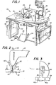
- FIGURE 1 illustrates a semi-automatic sewing system 10 incorporating the invention.
- System 10 is a microprocessor-based system which extends the capabilities of a sewing machine by enabling the operator to perform sewing procedures on a manual or semi-automatic basis, as will be more fully explained hereinafter.
- System 10 includes a conventional sewing machine 12 mounted on a work stand 14 consisting of a table top 16 supported by four legs 18.
- Sewing machine 12 which is of conventional construction, includes a spool 20 containing a supply of thread for stitching by a reciprocable needle 22 to form a seam in one or more pieces of material.
- a reciprocable needle 22 Surrounding needle 22 is a vertically movable presser foot 24 for cooperation with movable feed dogs (not shown) positioned within tabletop 16 for feeding material past the needle.
- a number of standard controls are associated with sewing machine 12 for use by the operator in controlling its functions.
- a handwheel 26 is attached to the drive shaft (not shown) of machine 12 for manually positioning needle 22 in the desired vertical position.
- Sewing speed is controlled by a speed sensor 15 which is actuated by a foot treadle 28, which functions like an accelerator.
- Vertical positioning of presser foot 24 can be controlled by heel pressure on foot treadle 28 which closes a switch 19 in speed sensor 15, which in turn causes the presser foot lift actuator 30 to operate.
- a leg switch 32 is provided for controlling the sewing direction of machine 12 by causing operation of reverse sew lever actuator 17.
- a toe switch 34 located adjacent to foot treadle 28 controls a conventional thread trimmer (not shown) disposed underneath the throat plate 36 of machine 12.
- Foot switch 38 on the other side of foot treadle 28 comprises a one-stitch switch for commanding machine 12 to sew a single stitch.
- sewing machine 12 and its associated manual controls are of substantially conventional construction, and may be obtained from several commercial sources.
- suitable sewing machines are available from Singer, Union Special, Pfaff, Consew, Juki, Columbia, Brother or Durkopp Companies.
- system 10 includes several components for adapting the sewing machine for semi-automatic operation.
- a pair of sensors 40 are mounted in laterally spaced-apart relationship in front of needle 22 and presser foot 24.
- a drive unit 42 comprising a variable speed direct drive motor, sensors for stitch counting and an electromagnetic brake for positioning of needle 22, is attached to the drive shaft of sewing machine 12.
- a main control panel 44 supported on a bracket 46 is provided above one corner of work stand 14.
- pneumatic control chassis 48 On one side of work stand 14 there is a pneumatic control chassis 48 containing an air regulator, filter and lubricator for the sewing machine control sensors, pneumatic actuators and other elements of system 10.
- a controller chassis 50 is located on the opposite side of work stand 14 for housing the electronic components of system 10.
- Chassis 50 includes a microprocessor controller 51, appropriate circuitry for receiving signals from sensors and carrying control signals to actuators, and a power module for providing electrical power at the proper voltage levels to the various elements of system 10.
- the microprocessor controller 51 may comprise a Zilog Model Z-80 microprocessor or any suitable unit having a read only memory (ROM) and random access memory (RAM) of adequate storage capacities.
- An auxiliary control panel 52 is mounted for sliding movement in one end of chassis 50. Operation and function of the foregoing components will become more clear in the following paragraphs.
- edge sensors 40 can be mounted directly on the housing of sewing machine 12, or supported by other suitable means.
- each sensor 40 comprises a lamp/photosensor which projects a spot of light 40a onto a reflective strip 54 on throat plate 36.
- the status of each sensor 40 is either on or off depending upon whether the light beam thereof is interrupted, such as by passage of material over reflective strip 54 in the direction of arrow 56 in FIGURE 3.
- Sensors 40 thus function to sense the presence of material being sewn and to signal the approach of the seam end by sensing passage of the trailing edge of the particular piece of material.
- a significant feature of the present invention comprises usage of at least one and possibly a plurality of sensors 40 positioned in mutually spaced relationship ahead -of needle 22 of sewing machine 12. Sensors 40 indicate whether or not the end of a particular seam is being approached. The condition of at least one sensor 40 changes as the trailing material edge passes thereunder to indicate approach of the seam end point. Sensors such as the Model 10-0672-02 available from Clinton Industries of Carlstadt, New Jersey, have been found satisfactory as sensors 40; however, infrared sensors and emitters, or pneumatic ports in combination with back pressure sensors could also be utilized, if desired. Any type of on/off sensors capable of detecting the presence or absence of material a preset distance in front of needle 22 can be utilized with apparatus 10 since the exact mode of their operation is not critical to practice of the invention.
- Sensors 40 can be mounted directly on the housing of sewing machine 12 or on a mounting assembly 58 as shown in FIGURE 4.
- Assembly 58 includes a transverse support bar 60 to which is attached a mounting block 62 for each sensor 40.
- Mounting blocks 62 are slidable and rotatable relative to support bar 60, and can be secured in any desired position thereon by means of set screws 64.
- Each sensor 40 is attached to the end of a rod 66 slidably extending through its corresponding block 62 and secured in place by set screw 68.
- Mounting assembly 58 thus facilitates adjustment of sensors 40 in the desired spaced relationship with respect to each other and with respect to sewing needle 22 in accordance with the shape of the material being sewn and other considerations of the particular sewing operation.
- Reflective tape 54 could also be repositioned accordingly.
- sensors 40 The operation and function of sensors 40 will be better understood upon reference to FIGURE 5.
- a seam 72 is sewn along a piece of material 74 as the material is fed through sewing machine 12, which is not shown in FIGURE 5, in the direction of arrow 76. Simultaneously, the number of stitches from start point 70 is being counted by the encoder within drive unit 42. Since reflective tape 54 is covered for a substantial portion of seam 72, the beams of sensors 40 are blocked and the conditions of both sensors are unchanged.
- Y represents the number of stitches sewn between start point 70 and end point 80 of seam 72. The value Y-X thus represents the number of stitches between points 78 and 80 for each seam.
- the values X and Y along with the last change in condition of sensors 40 for each seam are stored and used by microprocessor controller 51 to control sewing machine 12 during operation of system 10 in the AUTO mode. Since the length of each seam and the boundary profile of the material following each seam may vary, it will be appreciated that the values X and Y change with the particular seam and workpiece being sewn such that system 10 is adaptive. In addition to the more common devices found on a sewing machine, such as the presser foot lift actuator, reverse sew actuator and thread trimmer actuator, it will be appreciated that auxiliary devices including stackers, trimmers, guides and zig-zag lever actuators also can be controlled in this fashion as a function of stitch count and material edge detection.
- the seam being sewn may not approach the boundary of the bottom ply of material in some procedures, such as when sewing a patch pocket onto the front panel of a shirt.
- tape 54 can be positioned on a ply splitter or separator plate 82 positioned for passage between the upper and lower plies of material.
- Separator plate 82 can be attached to the housing of sewing machine 12 with a clamp band 84, or supported in any other suitable manner. Use of separator plate 82 thus insures that the boundary of the relevant ply of material being sewn is properly sensed.
- FIGURE 7 illustrates an alternative approach to sensing the boundary of the relevant ply of material being sewn which eliminates the need for a ply splitter or separator plate 82.
- each sensor 40 can comprise an infrared emitter 90 of adjustable radiation intensity positioned above an infrared sensor 92 mounted flush in the table top 16. This approach permits adjustment of the output of the infrared emitter 90 in accordance with the number of plies being sewn. For example, when sewing a single ply of material 94, the output of emitter 90 would be set to a relatively low level so that a single layer of material would block sensor 92 and thereby change the condition of sensor 40.
- the energy output level of emitter 90 would be set to a relatively higher level sufficient to penetrate one ply of material but not two plies of material.
- Suitable infrared emitters and sensors are available from Spectronics, Inc. of Richardson, Texas. Use of such variable sensitivity sensors 40, such as IR emitters and sensors, thus lends additional flexibility to system 10.
- the controls for sewing system 10 are found on operator or main control panel 44 and auxiliary control panel 52 shown in FIGURES 8 and 9.
- the primary controls are located on main panel 44 while auxiliary panel 52 contains adjustment controls.
- Panel 52 is normally closed within chassis 50, however, the panel can be pulled to an open position by means of handle 150 when adjustments are desired.
- main control panel 44 includes a power switch 154 to energize system 10.
- Switches 158, 156 and 160 are provided for respectively selecting the desired mode of operation.
- Lamps 156a, 158a and 160a are associated respectively with mode switches 156, 158 and 160 for indicating the particular mode selected.
- a three-digit display 162 and associated switch 164 are provided for displaying the operator sewing efficiency being achieved or a predetermined error code upon detection of a malfunction.
- System 10 computes and displays the percentage sewing efficiency using as a reference the sewing time standard established for the particular sewing operation. Time lost for personal or delay reasons is also recorded and displayed.
- Switch 166 allows the operator to select the desired efficiency base with lamp 166a indicating selection of efficiency per bundle sewn, and with lamp 166b indicating selection of total efficiency for a desired period.
- Hold switch 168 can be moved to the delay or personal positions as indicated by lamps 168a and 168b, respectively, to interrupt computation of efficiency readings during thread breakage, machine delays, etc. Efficiency computation ceases while hold switch 168 is activated, and the amount of personal or delay time accumulated by the microprocessor controller 51 appears on display 162.
- Switch 170 comprises an efficiency reset switch allowing the operator to clear and reset the sewing -efficiency values. If switch 166 is set to bundle, activation of reset switch 170 will clear and reset only the bundle efficiency value and the total values will not be affected. If switch 166 is set to total, actuation of reset switch 170 will clear and reset both the bundle and total efficiency values.
- Switch 172 on control panel 44 is provided for controlling the bobbin-monitoring capability of system 10. This is done by programming microprocessor controller 51 with the number of stitches required to empty a full bobbin in sewing machine 12. Upon installation of a full bobbin, the operator can move switch 172 to the full position and then use sewing machine 12 in any one of the three modes. Upon depletion of the bobbin, switch 172 is then moved to the empty position to terminate counting with the number of stitches required to empty the bobbin. The microprocessor controller 51 thereafter monitors the number of stitches sewn and illuminates lamp 174 and activates a horn behind grill 176 on panel 44 when the stitch count reaches a predetermined percentaqe of the stored value to signal the need to change the bobbin.
- Main control panel 44 also includes a one-stitch switch 182 to complement foot switch 38 shown in FIGURE 1.
- Switch 182 can be used in any one of the three operational modes of system 10. Actuation of switch 182 will cause sewing machine 12 to sew a single stitch and leave needle 22 in the down position.
- system 10 includes several controls for further adjusting the operating characteristics of sewing machine 12.
- Switch 184 can be depressed in the auto mode of operation to modify acceleration and deceleration rates programmed into system 10 in the teach mode.
- microprocessor controller 51 accelerates or decelerates sewing machine 12 via drive unit 42 in accordance with the rates programmed into system 10 in the teach mode.
- switch 184 is not actuated, the acceleration and deceleration rates can be changed with rotary switch 186 located on auxiliary panel 52.
- a second rotary switch 188 located on panel 52 allows selection of the desired number of slow speed stitches at the beginning of each seam in the auto mode to reduce thread pull-out and other problems at the start of a seam.
- Switch 190 can be depressed in the auto mode of operation to modify sewing speeds programmed into system 10 in the teach mode.
- switch 190 When switch 190 is activated in the auto mode, which is indicated by lamp 190a, the speed of the sewing machine 12 can be varied by operation of foot treadle 28.
- the foot treadle 28 acts as an on/off switch such that the speed of sewing machine 12 in the auto mode, with the foot treadle fully depressed, will follow the speed profile sewn in the teach mode.
- Rotary switch 192 permits the operator to select the amount of speed up in the auto mode over the speed profile programmed during the teach mode.
- a second rotary switch 194 permits selective reduction of the sewing pause and presser foot up time intervals over the programmed intervals.
- Switch 196 permits the operator to regain manual control of sewing machine 12 in the auto mode of operation.
- System 10 utilizes a combination of stitch counting and edge detection techniques to control seam lengths and end points; however, there may be situations where the operator anticipates material handling or other difficulties with certain seams.
- Actuation of switch 196 in the auto mode coupled with removal of pressure from foot treadle 28, causes system 10 to revert to the manual mode so that the operator can manually complete the seam.
- System 10 will remain in the manual mode until the operator can manually complete the seam and raise presser foot 24.
- presser foot 24 is lowered again and foot treadle 28 is depressed, system 10 will automatically revert to the auto mode and resume sewing of the next seam as programmed.
- Depression of switch 196 in the teach mode functions to program a command into microprocessor controller 51 at that point along the seam to subsequently invoke the seam length control function in the auto mode so that the seam can be completed manually.
- Lamp 196a indicates actuation of switch 196.
- auxiliary control panel 52 further includes a rotary switch 198 for reducing maximum speed of sewing machine 12 in the manual, teach, and auto modes of operation to facilitate the training of operators for system 10.
- Sewing machine 12 operates as follows. Actuation of switch 154 on control panel 44 energizes sewing system 10. Sewing machine 12 can be operated manually by depressing switch 160 and manipulating the hand wheel 26, foot treadle 28, and switches 19, 32, 34 and 38 to control the sewing machine. Foot treadle 28 functions as an accelerator in the manual mode to control the sewing speed of machine 12.
- the teach mode of operation can be selected with switch 156. Typically, this is done before beginning a bundle of pieces of similar sizes and/ or shapes. As the first piece is sewn manually by the operator, the microprocessor controller 51 records and stores the following:
- This information is utilized by the microprocessor controller 51 to automatically control operation of sewing machine 12 in the auto mode of system 10.
- -Single stitches sewn at the end of each seam by depression of one-stitch switch 38 or switch 182 are simply added to the taught stitch count.
- needle 24 is left in the down position.
- Manually entered single stitches, but not the pauses therebetween, are added to the stored seam stitch count.
- pauses between the single stitches manually entered in the teach mode are ignored by microprocessor controller 51 later in the auto mode such that sewing machine 12 continues at constant speed through the manually entered stitches and then stops, thereby facilitating the teaching of new operators.
- switch 158 can be actuated to place system 10 in the auto mode for semi-automatic sewing of the remaining pieces.
- the operator positions the next piece for sewing of the first seam thereof, and then depresses foot treadle 28 to initiate control of sewing machine 12 by the microprocessor.
- Foot treadle 28 in the auto mode simply functions as an on/off switch with operation of sewing machine 12 being controlled by microprocessor 51. Depression of foot treadle 28 thus causes repeat of the programmed sewing operation as the operator continues to handle and guide the material through sewing machine 12.
- the microprocessor controller 51 does not slow sewing machine 12 or pause between stitches which were added in the teach mode by depression of one-stitch switches 38 or 182. Rather, a substantially constant sewing speed, as modified by switch 190, is maintained as the sewing machine approaches the end of each seam, thereby saving considerable time. Release of foot treadle 28 interrupts the automatic sewing sequence.
- microprocessor 51 is programmed to set up a window in which the change in status of sensors 40 is expected, thereby eliminating spurious signals.
- this window can be defined as 75-l05% of the stitch count at the time of the last status change in sensors 40 before the end of the seam, which stitch count is represented by X in FIGURE 5.
- microprocessor controller 51 does not begin to look for the characteristic pattern of sensors 40, and the controller is not responsive to a change in sensor status, until 75% of X stitches have been sewn.
- Y-X terminal stitches are sewn to end the seam at a precise point.
- microprocessor 51 automatically reverts to overall stitch counting for determining seam length and stops sewing machine 12 after Y stitches. Inaccuracies due to stitch counting therefore are reduced to a very small portion of the seam length.
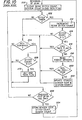
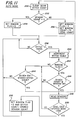
- FIGURES 10 and 11 there are shown the flowcharts of the control logic utilized by sensors 40 in the teach and auto modes of system 10.
- the term sensor code means the on/off condition of sensors 40.
- stitch count means the number of stitches taken in a seam.
- sensor count means the number of stitches at the last change in the sensor code.
- window means the zone in which microprocessor 51 is looking for a sensor code corresponding to the programmed sensor code.
- the teach. mode control logic for each seam begins at 200 by clearing the seam stitch count, sensor count and end tack flag. An inquiry is made at 202 whether a stitch has been taken. If no stitch has been taken, an inquiry is made at 204 whether a reverse command has been received by sewing machine 12. If no stitch has been taken-and there has been no reverse command, an inquiry is made at 206 whether pressure foot 24 is up or whether the thread has been trimmed. If no stitch has been taken and there has been a reverse command, an inquiry about the stitch count is made at 208. If the stitch count is less than five the program proceeds directly to 206. If the stitch count is five or more, the end tack flag is set at 210 before proceeding to 206.
- the stitch count is incremented at 212 before an inquiry about the stitch count is made at 214. If the stitch count is five or more, an inquiry is made at 216 as to whether the end tack flag is set. If the end tack flag is not set, fabric sensors 40 are read at 218 before an inquiry is made at 220 whether the condition or code of sensors 40 matches the previous code. If not, then the stored sensor code and sensor count are updated at 222 before proceeding to 204. Depending upon the position of pressure foot 24 or the status of the thread trimmer at 206, the program may go back to 202 or store the sensor code, stitch count and sensor count at 224 before returning to 200.
- a sample program listing the microprocessor controller 51 of system 10 in the teach mode is set forth below.
- the program is particularly adapted for a Zilog Z-80 microprocessor, and is written in Z-80 assembly language in accordance with the Z-80 CPU Manual available from the Zilog Corporation.
- the program is subdivided into tables as follows:
- the control logic in the auto mode begins by clearing the seam stitch count at 230 before checking the sensor count at 232. If the sensor count is less than five, the window flag is set to zero at 234. If the sensor count is five or more, the window flag is set to one and the window count is set to .75 of the sensor count at 236. An inquiry is then made at 238 whether a stitch has been taken, .and if not, the system continues looking for a stitch. If a stitch has been taken, the stitch count is incremented at 240 before checking the window flag at 242. If the window flag is zero and thus not equal to one, the stitch count is compared to the stored stitch count at 244, after which the program may go to 238 or 230.
- the stitch count is compared to the window count at 246. Should the stitch count be less than the window count, the program then goes to 244. Should the stitch count be equal to or greater than the window count, sensors 40 are then read at 248 before comparing the sensor code to the stored sensor code at 250. If the sensor code does not match the stored sensor code, the program proceeds to 244. Should the sensor code match the stored sensor code, the window flag is set to zero and the stitch count is set to the stored sensor count at 252 before proceeding back to 238.
- a program listing for the microprocessor controller 51 of system 10 in the auto-mode is set forth below.
- the program is particularly adapted for a Zilog Z-80 microprocessor, and is written in Z-80 assembly language in accordance with the Z-80 CPU Manual available from Zilog Corporation.
- the program is subdivided tables as follows:
- an optional interface module 300 which can be incorporated into semi-automatic sewing system 10 herein to control auxiliary devices as a function of stitch count.
- Interface module 300 is coupled between the microprocessor controller 51 and the auxiliary device to be controlled.
- the interface module 300 includes six input channels 302-312 and six corresponding output channels 302a-312a. Some of the inputs and corresponding outputs can be connected to devices usually found on a sewing machine, such as the presser foot lift actuator, reverse sew actuator and thread trimmer actuator. The other inputs and corresponding output channels of interface module 300 can be utilized to control auxiliary devices such as stackers, trimmers, guides, zig-zag actuators, and so forth.
- interface module 300 Under the control of microprocessor controller 51, interface module 300 receives command switch closure type input signals and generates appropriate output actuation signals. Thus, in the teach or manual modes, a device can be operated manually through the appropriate command switch. When a device is manually actuated in the teach mode, however, interface module 300 senses control inputs to the device and transmits corresponding signals which are stored in the microprocessor controller 51 as a function of stitch count. In subsequent playback of the programmed operation in the auto mode, actuation of the devices through module 300 will be controlled automatically by microprocessor controller 51.
- FIGURE 12 illustrates interface module 300 in conjunction with a split needle bar, double needle sewing machine 314, which is mounted on table top 16 similar to single needle sewing machine 12 shown in FIGURE 1.
- the various standard controls associated with sewing machine 314 have-been omitted from FIGURE 12, however, it will be appreciated that many of these controls are the same as those of sewing machine 12 shown in FIGURE 1.
- a pair of sensors 40 and associated retroreflective strip (not shown) are mounted on machine 314.
- Sewing machine 314 includes a left needle 316 with associated presser foot and a right needle 318 with associated presser foot.
- Needles 316 and 318 can be operated in unison or individually by manual actuation of conventional throw- out mechanisms (not shown) connected to the needles.
- Suitable double-needle sewing machines such as the Pfaff 542 or Juki LH-527, are commercially available.
- a pair of actuators 320 and 322 are connected to the throw-out mechanisms of needles 316 and 318, respectively.
- a command switch 324 is connected between the needle throwout actuators 320 and 322 and auxiliary input channels 308 and 310 of module 300. The corresponding output channels 308a and 310a are wired to the actuators 320 and 322.
- needles 316 and 318 can be thrown out as desired by manual operation of switch 324, however, in the teach mode an appropriate control signal is generated and transmitted by module 300 for storage in the microprocessor controller 51 as a function of stitch count.
- operation of actuators 320 and 322 is controlled automatically by microprocessor controller 51 without stopping sewing machine 314.
- FIGURE 13 illustrates the operation of a semi- automatic sewing system 10 with double needle sewing machine 314 sewing a double seam around a corner of a piece 326.
- both needles 316 and 318 are positioned down and operate to sew parallel seams 330 and 332 along one edge of piece 326.
- the right needle 318 is raised or thrown-out after R stitches have been sewn.
- Sewing is continued with the left needle 316 of sewing machine 314 through point 335, where the condition of sensors 40 change at X stitches, as was discussed in reference to FIGURE 5, until stopping at point 336 after Y stitches.
- the values R and X could be the same or different, depending upon the particular seam and shape of material being sewn.
- Piece 326 is then turned before Z initial stitches are sewn by the left needle 316, such as by manipulation of the one-stitch switch, before stopping at point 338 along seam 330.
- the right needle 318 is lowered again at point 334 and sewing of seam 332 is resumed as the left needle continues from point 338 sewing sear 330.
- the values R, X, Y and Z along with the last change in condition of sensors 40 for each seam sewn in the teach mode are stored in microprocessor controller 51.
- the throw-out mechanism for right needle 318 is activated at stitch count R as the left needle 316 continues stitching.
- the characteristic sensor 40 pattern is seen in the window (.75X-1.05X) surrounding X, Y-X terminal stitches are sewn before stopping at end point 336 in accordance with a combination of stitch counting and edge detection as described hereinbefore.
- FIGURES 14-18 illustrate modifications which can be incorporated into system 10 to improve its performance. These modifications are primarily in the nature of programming and/or logic changes which improve the adaptability, reliability, accuracy and capability of system 10.
- the microprocessor controller 51 could be programmed to initiate deceleration of machine 12 at a fixed preset number of stitches before the end of each seam; however, for seams of relatively short lengths where the sewing machine would not be operating at top speed, premature deceleration and thus wasted time would result. It is therefore desirable to maximize the time during which machine 12 operates at its highest speed and to adaptively control the point at which deceleration commences to minimize the number of slow stitches sewn at the terminal end of each seam.
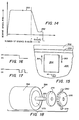
- FIGURE 14 illustrates a typical sewing speed profile for a seam sewn in accordance with the modified logic explained below.
- the microprocessor controller 51 of system 10 measures and stores the sewing speed profile or speed per stitch, the total number of stitches Y sewn, and the number of stitched Y-X sewn after the last status change in sensors 40 for each seam. These values are used by the microprocessor controller 51 in the auto mode to compute the adaptive number of stitches M before the end of each seam at which to initiate deceleration from the high speed of operation, such as 2000-5000 rpm, represented by line 350.
- the microprocessor controller 51 initiates deceleration of the motor end drive unit 42 and monitors the number of stitches sewn at the "stopping" speed represented by line 352.
- the stopping speed means a speed such as 300 rpm from which sewing machine 12 can be halted substantially instantaneously.
- One stitch or less at the stopping speed represented by line 352 is considered acceptable, however, if the microprocessor controller 51 measures that more than one stitch was sewn at the stopping speed, the stored value M is decremented by the excess number of slow stitches sewn. If, on the other hand, the microprocessor controller 51 measures that too many stitches were sewn and that the seam end was overrun, the stored value M is increased.
- the stored value M for each seam is thus adaptively adjusted during each sewing operation to maintain the number of stitches sewn at the slow speed to one stitch or less.
- a window of 0.75X to 1.05X was set up around the number of stitches X sewn at the time of the last status change or "toggle" in the sensors 40 in order to eliminate spurious signals.
- This logic works well with pieces of slightly different sizes, but has been found to be a limiting factor when sewing pieces of substantially smaller or larger sizes wherein the requisite sensor state may not appear in such a window. Also, the logic of storing only the last sensor condition for comparison in determing the end point of each seam may not be accurate for all sewing operations.
- FIGURE 15 shows a sewing operation which illustrates the advantages of the revised sensor logic described more fully hereinafter.
- a patch pocket 354 is set on a pants panel 356, a riser or yoke 358 is sometimes provided above the pocket usually for purposes of style.
- the sensor state contains one change or toggle as represented by FIGURE 16.
- the sensor 40 toggles more than once as represented by FIGURE 17 as it senses the boundary of pocket 354 and then yoke seam 359.
- the last sensor status is correct, it references the yoke seam 359 instead of pocket 354.
- reliance can be placed on the last sensor state for terminating the right-hand and bottom seams, but not for terminating the left-hand seam.
- the status changes or toggles of sensors 40 for each seam are stored by the microprocessor controller 51 in the teach mode.
- the microprocessor controller 51 is programmed to compare the sensor toggles with the stored toggle history for that seam as each seam is being sewn so that, once the proper toggle sequence has been achieved, countdown of Y-X terminal stitches can be initiated to complete the seam.
- the toggle sequences programmed into system 10 in the teach mode are thus utilized to control seam lengths and end points in the auto mode.
- the revised logic provides for adaptive adjustment of the number of stitches before the end of each seam at which deceleration of sewing machine 12 is initiated to prevent overruning the seam end points. If the last toggle condition of sensors 40 occurs such that the stored value M is less than the value of Y-X stitches stored in microprocessor controller 51, the logic also provides for decrement back to the previous sensor toggle point as the basis for terminating the seam in the auto mode. For example, in the case of the left-hand seam on the patch pocket 354 shown in FIGURE 15, the last off/on toggle on the far side of yoke seam 359 would be checked and determined to afford insufficient time to decelerate sewing machine 12.
- the microprocessor controller 51 would then automatically go back to the on/off sensor toggle at the front edge of yoke seam 359 and check again if a sufficient number of stitches remained to decelerate sewing machine 12 to a precise stop, and, if not, the controller would then back up once again-to the off/on toggle occurring at the pocket boundary as the basis for terminating the seam.
- a further revision to the sensor logic comprises checking the sensor condition at the start of each seam in the auto mode against the stored sensor condition programmed in the teach mode. If the sensed and stored initial sensor conditions are not the same, the system 10 reverts to pure stitch counting to determine the seam length and end point. This feature is particularly useful for very short seams where the condition of sensors 40 may not consistently be the same due to irregularities in the material, etc.
- the revised sensor logic eliminates the use of a window around the adaptive value ot X stitches for each seam.
- the purpose of this window was to avoid picking up spurious signals from false sensor toggles which could prematurely initiate termination of a seam.
- the sensor logic can also be revised to include the requirement that sensor toggles must last for more than one stitch before the microprocessor controller 51 will respond to such toggles. Momentary sensor toggles which endure for less than one stitch are thus filtered out as spurious signals.
- Another important feature represented by the modified control logic for system 10 comprises enhancement of the seam length accuracy from +1 stitch to +0.5 stitch.
- a status change or toggle of sensors 40 can occur anytime during the one revolution of the motor within drive unit 42 required to form a stitch.
- a +1 stitch accuracy is obtained when sensors 40 change state immediately before or immediately after the needle position where the microprocessor controller 51 recognizes such changes.
- many sewing machine feed mechanisms only advance material over a portion of the stitch forming cycle. For example, in a needle feed machine, advancement of the material occurs when the needle is in the material. Material advancement is continuous and uniform throughout the complete stitch forming cycle in a continuous feed machine. It is thus desirable to be able to read sensors 40 more than once during each stitch cycle and to compensate for the particular material feed characteristics for the sewing machine 12.
- FIGURE 18 shows an exploded perspective illustration ,of the modified drive unit 366 which can be utilized in system 10.
- Drive unit 366 includes a housing 368 enclosing a variable speed drive motor 370 having a drive shaft 372 coupled directly to the drive shaft of sewing- machine 12.
- An electromagnetic brake 374 is secured to shaft 372 as are a sensor vane 376 and the hand wheel 26, which has been omitted from FIGURE 18 for clarity.
- the sensor vane 376 includes a plurality of uniformly spaced openings therearound which cooperate-with sensors 378 and 380 to provide a more precise measurement to the microprocessor controller 51 of the angle in the sewing cycle at which each status change in sensors 40 occurs.
- sensor vane 376 includes 36 evenly spaced circumferential openings therein to achieve a resolution of 10°.
- Sensor 378 provides a reference or sync signal against which the motor angle signals from sensor 380 are compared within microprocessor controller 51 to fix the angular position in the sewing machine cycle, and thus the needle position, where each toggle of edge sensors 40 occurs.
- any suitable interrupt type sensors can be used for sensors 378 and 380.
- a Model TIL 147 photoptical sensor from Texas Instruments Corporation can be used for sensor 380.
- a Model TL 172C hall effect sensor from Texas Instruments Corporation can be used for sensor 378.
- the microprocessor controller 51 can be programmed with an algorithm for deciding whether a stitch should be added or deleted at the end of the seam.
- the algorithm for determining the number of stitches to be sewn after the relevant sensor toggle is as follows:
- microprocessor controller 51 In order to use the foregoing algorithm correctly, system 10 must be provided with the particular material feed characteristics of sewing machine 12.
- One way to provide this information to microprocessor controller 51 is to input the angles start and ⁇ stop via the keyboard 167 on auxiliary control panel 52. Another way to do this would be to provide a calibration software routine for the microprocessor controller 51 which would enable it to self calibrate and automatically determine the ⁇ start and ⁇ stop values for a given machine and stitch length setting.
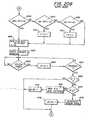
- FIGURES 19 and 20a and b there are shown the flow charts for the control logic utilized by sensors 40 in the modified teach and auto modes of system 10.
- the meanings of the variables are as follows:
- DA sensed angle of motor 370 at which final sensor toggle occurred in the auto mode.
- the teach mode control logic for each seam begins at 390 with the command to sew the next seam after which sensors 40 are enabled at 392.
- the values T, Y and N are then set to zero at 394.
- the control logic in the auto mode begins at 420 by setting the variables N, L and K to zero.
- a command is given to sew the next seam after which an inquiry is made at 424 whether it is the first time that seam is being sewn. If so, M is set to Y - 1 at 426 before proceeding to 428.
- the seam stopping variable M is initially set to one stitch less than the taught number of stitches between transition of sensors 40 and the seam end point for the first time that seam is sewn in the auto mode. If it is not the first time that seam is being sewn, the logic proceeds directly from 424 to 428.
- an inquiry is made at 430 whether there has been a change of state or toggle in sensors 40 since the last stitch. If so, an inquiry is made at 432 whether N equals one. If not, then at 434 N is set to one and DA is set to the motor angle before returning to 428. If N does equal one, then N is set to zero and the one stitch toggle is ignored at 436 before returning to 428. A sensor change on each of two consecutive stitches thus indicates a momentary or false toggle of sensors 40.
- N is incremented at 440. L corresponds to the number of sensor toggles sensed in the auto mode. Then an inquiry is made at 442 whether L equals T. If not, N is again set to zero at 444 before sewing another stitch at 428. If L equals T, which means that the taught and sensed toggle histories for that seam correspond, Y is decremented at 446 to subtract the stitch count registered after sensors 40 changed state.
- an inquiry is made at 448 whether the absolute value of DA minus DT is less than DI. If not, another inquiry is made at 450 whether the difference between DA and DT is less than minus DI. If the answer to the inquiry of 450 is yes, Y is decremented at 452 before proceeding to 454. If the answer to the inquiry of 450 is no, another inquiry is made at 456 whether the difference between DA and DT is greater than DI. After 456, the logic proceeds to 454, however, Y is first incremented at 458 if the answer to the inquiry is yes. Decisions 448, 450 and 456 thus comprise the algorithm by which the microprocessor controller 51 determines how many terminal stitches to take after transistion of sensors 40.
- K does not equal Y
- an inquiry is made at 470 whether K is less than Y. If K is less than Y, indicating that braking started too soon, Y - K additional stitches are sewn at 472 and M is decremented at 474 before returning to 420.
- the seam stopping variable M is monitored and adaptively adjusted, if necessary, each time•the seam is sewn in the auto mode. If K is not less than Y, indicating that the dynamic capabilities of system 10 have been exceeded, an error code is generated at 476 and M is incremented at 478 so that braking is initiated sooner before returning to 420.
- a program listing, with comments, for the microprocessor controller 51 of system 10 in the modified teach and auto modes discussed above is set forth in Table 7 below.
- the program is particularly adapted for a Zilog Z-80 microprocessor, and is written in Z-80 assembly language in accordance with the Z-80 CPU manual available from Zilog Corporation.
- the present invention comprises an adaptive sewing machine control system having significant advantages over the prior art.
- the system herein utilizes a combination of stitch counting and edge detection to achieve precise seam lengths and end points.
- a sensor is located ahead of the sewing needle for detecting the approach of the material boundary following each seam.
- Most of the operations of the sewing machine are controlled by the microprocessor as a function of stitch count, however, the only stitch counting that is utilized to determine seam length comprises a relatively small variable number of stitches at the end of each seam. Countdown of the variable terminal number of stitches can be initiated by correspondence of the taught and sensed final toggle conditions or correspondence of the taught and sensed toggle histores.
- Spurious signals which could cause premature initiation of the final stitch countdown are avoided either by setting up a window around the stitch count corresponding to the last change in sensor condition before the end of the seam, or by ignoring momentary toggles of the edge sensors. Other advantages will be apparent to those skilled in the art.
Landscapes
- Engineering & Computer Science (AREA)
- Mechanical Engineering (AREA)
- Textile Engineering (AREA)
- Sewing Machines And Sewing (AREA)
Priority Applications (1)
| Application Number | Priority Date | Filing Date | Title |
|---|---|---|---|
| AT81303046T ATE18270T1 (de) | 1980-07-14 | 1981-07-03 | Regeleinrichtung fuer naehmaschine. |
Applications Claiming Priority (4)
| Application Number | Priority Date | Filing Date | Title |
|---|---|---|---|
| US168525 | 1980-07-14 | ||
| US06/168,525 US4359953A (en) | 1980-07-14 | 1980-07-14 | Control system for sewing machine |
| US210197 | 1980-11-26 | ||
| US06/210,197 US4403558A (en) | 1980-07-14 | 1980-11-26 | Control system for sewing machine |
Publications (3)
| Publication Number | Publication Date |
|---|---|
| EP0044648A2 true EP0044648A2 (de) | 1982-01-27 |
| EP0044648A3 EP0044648A3 (en) | 1982-02-03 |
| EP0044648B1 EP0044648B1 (de) | 1986-02-26 |
Family
ID=26864211
Family Applications (1)
| Application Number | Title | Priority Date | Filing Date |
|---|---|---|---|
| EP81303046A Expired EP0044648B1 (de) | 1980-07-14 | 1981-07-03 | Regeleinrichtung für Nähmaschine |
Country Status (3)
| Country | Link |
|---|---|
| US (1) | US4403558A (de) |
| EP (1) | EP0044648B1 (de) |
| DE (1) | DE3173868D1 (de) |
Cited By (9)
| Publication number | Priority date | Publication date | Assignee | Title |
|---|---|---|---|---|
| DE3216993A1 (de) * | 1982-05-06 | 1983-11-17 | Pfaff Industriemaschinen Gmbh, 6750 Kaiserslautern | Naehmaschine mit einer einrichtung zum herstellen von formnaehten |
| EP0103364A2 (de) | 1982-08-30 | 1984-03-21 | Microdynamics, Inc. | Verfahren und Vorrichtung zum Verlangsamen der geschwindigkeit und Anhalten eines Nähmaschinenantriebsmotors |
| DE3324715A1 (de) * | 1983-07-08 | 1985-01-24 | Pfaff Industriemaschinen Gmbh, 6750 Kaiserslautern | Naehmaschine mit einer einrichtung zum ansteuern eines vorbestimmten endpunktes einer naht |
| US4534304A (en) * | 1982-10-06 | 1985-08-13 | Durkoppwerke Gmbh | Stitch correction method and apparatus for a sewing machine |
| DE3614104A1 (de) * | 1985-04-25 | 1986-10-30 | Brother Kogyo K.K., Nagoya, Aichi | Naehmaschine |
| US4665848A (en) * | 1984-02-13 | 1987-05-19 | Levi Strauss & Co. | Method and apparatus for automatically hemming garments |
| GB2208251A (en) * | 1987-07-14 | 1989-03-15 | Tokai Ind Sewing Machine | Automatic embroidering machine |
| EP0204628B1 (de) * | 1985-06-03 | 1990-10-31 | Prouvost S.A. | Verfahren und Nähmaschine um eine Naht automatisch in einem bestimmten Abstand vom Rand eines Werkstückes fertig zu machen |
| DE19704998B4 (de) * | 1996-02-09 | 2010-01-07 | Juki Corp., Chofu | Spulenwechselvorrichtung |
Families Citing this family (11)
| Publication number | Priority date | Publication date | Assignee | Title |
|---|---|---|---|---|
| DE3228789A1 (de) * | 1982-08-02 | 1984-02-02 | Quick-Rotan Elektromotoren GmbH, 6100 Darmstadt | Antriebs- und steuervorrichtung fuer naehmaschinen, naehautomaten und dergleichen |
| US4526114A (en) * | 1983-02-25 | 1985-07-02 | Microdynamics, Inc. | Method and apparatus for sewing mitered corners on a split needle bar sewing machine |
| DE3323214C1 (de) * | 1983-06-28 | 1984-10-11 | Dürkoppwerke GmbH, 4800 Bielefeld | Optoelektronische Abtastvorrichtung an einer Naehmaschine |
| US4565140A (en) * | 1984-02-06 | 1986-01-21 | Microdynamics, Inc. | Method and apparatus for automatically adjusting the sensitivity of edge sensors in a semi-automatic sewing machine |
| US4555997A (en) * | 1984-05-29 | 1985-12-03 | The Singer Company | Semi-automatic sewing machine control system |
| US4773344A (en) * | 1984-10-18 | 1988-09-27 | Tokyo Juki Industrial Co., Ltd | Sewing machine control device |
| WO1986003034A1 (fr) * | 1984-11-13 | 1986-05-22 | Quick-Rotan Elektromotoren Gmbh | Dispositif processeur pour machines a coudre |
| JPS61249494A (ja) * | 1985-04-27 | 1986-11-06 | ジューキ株式会社 | ミシンの布送り量自動変更装置 |
| JPS625388A (ja) * | 1985-06-29 | 1987-01-12 | ブラザー工業株式会社 | ミシンにおける布端部の定寸縫い装置 |
| JPS6253698A (ja) * | 1985-09-03 | 1987-03-09 | 三菱電機株式会社 | 2本針縫製装置 |
| CN116856123A (zh) * | 2023-07-06 | 2023-10-10 | 安徽杰羽制鞋机械科技有限公司 | 一种罗拉车的示教编程方法 |
Family Cites Families (17)
| Publication number | Priority date | Publication date | Assignee | Title |
|---|---|---|---|---|
| FR1477374A (fr) * | 1965-05-12 | 1967-04-14 | Union Special Machine Co | Mécanisme d'avance commandé automatiquement pour machine à coudre |
| US3457886A (en) * | 1967-06-06 | 1969-07-29 | Union Special Machine Co | Sewing apparatus and control means therefor |
| US3654882A (en) * | 1969-08-11 | 1972-04-11 | Pneumatic Systems Inc | Automatic control system for sewing machines |
| US3609373A (en) * | 1970-05-18 | 1971-09-28 | Singer Co | Photoelectric sensors and circuitry for edge-guiding systems for sewing machines |
| DE2107351A1 (de) * | 1971-02-16 | 1972-08-31 | Union Special Maschinenfab | einrichtung zum Abtasten der Nähgutkante und automatischem Auslösen eines Steuerimpulses zum gezielten Einschalten einer Einrichtung bei einer Nähmaschine für manuell gesteuerten Arbeitsablauf |
| US3750603A (en) * | 1971-04-05 | 1973-08-07 | Clevepak Corp | Apparatus for controlling a sewing machine thread cutter |
| US3799084A (en) * | 1972-09-22 | 1974-03-26 | Campus Sweater & Sportswear Co | Feed control for operationally programmed sewing machine |
| FR2208409A5 (fr) * | 1972-11-24 | 1974-06-21 | Jaep Sa Ets | Dispositif pour la commande automatique sequentielle d'une machine à coudre industrielle |
| DE2448887A1 (de) * | 1974-10-14 | 1976-04-22 | Pfaff Ind Masch | Naehmaschine zum aufnaehen eines stoffstreifens auf einen stoffzuschnitt |
| GB1526209A (en) * | 1974-12-23 | 1978-09-27 | Secretary Industry Brit | Automatic stitching machines |
| US4038931A (en) * | 1975-11-25 | 1977-08-02 | Union Special Corporation | Fabric panel discontinuity sensor |
| DE2710418C2 (de) * | 1977-03-10 | 1985-04-25 | Dürkoppwerke GmbH, 4800 Bielefeld | Nähmaschine mit einem Kantenführer |
| US4092937A (en) * | 1977-03-21 | 1978-06-06 | The Singer Company | Automatic stitching by programmable sewing machine |
| US4160424A (en) * | 1978-02-13 | 1979-07-10 | Dan River Incorporated | Stitch counter for a sewing machine |
| US4195582A (en) * | 1978-09-14 | 1980-04-01 | Teledyne Mid-America Corporation | Sewing machine stitching control system |
| GB2059636B (en) * | 1979-09-07 | 1984-02-15 | Halle Models Ltd | Sewing machines |
| FR2467902A1 (fr) * | 1979-10-18 | 1981-04-30 | Valton Sa | Dispositif pour la mise automatique en position d'une piece de vetement en vue de l'execution d'une couture |
-
1980
- 1980-11-26 US US06/210,197 patent/US4403558A/en not_active Expired - Lifetime
-
1981
- 1981-07-03 DE DE8181303046T patent/DE3173868D1/de not_active Expired
- 1981-07-03 EP EP81303046A patent/EP0044648B1/de not_active Expired
Cited By (11)
| Publication number | Priority date | Publication date | Assignee | Title |
|---|---|---|---|---|
| DE3216993A1 (de) * | 1982-05-06 | 1983-11-17 | Pfaff Industriemaschinen Gmbh, 6750 Kaiserslautern | Naehmaschine mit einer einrichtung zum herstellen von formnaehten |
| EP0103364A2 (de) | 1982-08-30 | 1984-03-21 | Microdynamics, Inc. | Verfahren und Vorrichtung zum Verlangsamen der geschwindigkeit und Anhalten eines Nähmaschinenantriebsmotors |
| EP0103364A3 (en) * | 1982-08-30 | 1984-09-05 | Microdynamics, Inc. | A method and apparatus for decelerating and stopping a sewing machine motor |
| US4534304A (en) * | 1982-10-06 | 1985-08-13 | Durkoppwerke Gmbh | Stitch correction method and apparatus for a sewing machine |
| DE3324715A1 (de) * | 1983-07-08 | 1985-01-24 | Pfaff Industriemaschinen Gmbh, 6750 Kaiserslautern | Naehmaschine mit einer einrichtung zum ansteuern eines vorbestimmten endpunktes einer naht |
| US4665848A (en) * | 1984-02-13 | 1987-05-19 | Levi Strauss & Co. | Method and apparatus for automatically hemming garments |
| DE3614104A1 (de) * | 1985-04-25 | 1986-10-30 | Brother Kogyo K.K., Nagoya, Aichi | Naehmaschine |
| EP0204628B1 (de) * | 1985-06-03 | 1990-10-31 | Prouvost S.A. | Verfahren und Nähmaschine um eine Naht automatisch in einem bestimmten Abstand vom Rand eines Werkstückes fertig zu machen |
| GB2208251A (en) * | 1987-07-14 | 1989-03-15 | Tokai Ind Sewing Machine | Automatic embroidering machine |
| GB2208251B (en) * | 1987-07-14 | 1992-02-12 | Tokai Ind Sewing Machine | Embroidering machine |
| DE19704998B4 (de) * | 1996-02-09 | 2010-01-07 | Juki Corp., Chofu | Spulenwechselvorrichtung |
Also Published As
| Publication number | Publication date |
|---|---|
| EP0044648A3 (en) | 1982-02-03 |
| US4403558A (en) | 1983-09-13 |
| DE3173868D1 (en) | 1986-04-03 |
| EP0044648B1 (de) | 1986-02-26 |
Similar Documents
| Publication | Publication Date | Title |
|---|---|---|
| EP0044648B1 (de) | Regeleinrichtung für Nähmaschine | |
| EP0068625B1 (de) | Stichlängen-Kontrollvorrichtung für Nähmaschine | |
| US4359953A (en) | Control system for sewing machine | |
| EP0117713B1 (de) | Verfahren und Vorrichtung um Hemdkragenspitzen auf einer Nähmaschine mit zwei Nadeln zu nähen, welche unabhängig voneinander angetrieben werden können | |
| US4548143A (en) | Method and apparatus for varying the length or stitches sewn by a sewing machine in dependence upon sewing speed | |
| US4408554A (en) | Automatic needle thread control apparatus | |
| EP0103364B1 (de) | Verfahren und Vorrichtung zum Verlangsamen der geschwindigkeit und Anhalten eines Nähmaschinenantriebsmotors | |
| EP0124211B1 (de) | Verfahren zum automatischen Zuführen des Nähgutes zu einer Nähmaschine, und Nähmaschine zur Durchführung des Verfahrens | |
| US4534304A (en) | Stitch correction method and apparatus for a sewing machine | |
| US4545310A (en) | Method and apparatus for accurately controlling the seam margins produced by a semi-automatic sewing machine | |
| US4555997A (en) | Semi-automatic sewing machine control system | |
| US4565140A (en) | Method and apparatus for automatically adjusting the sensitivity of edge sensors in a semi-automatic sewing machine | |
| US5653186A (en) | Apparatus and method for controlling sewing machine | |
| US4648337A (en) | Work edge guiding device for sewing machine | |
| US5146862A (en) | Sewing machine-driving apparatus | |
| US4858545A (en) | Sewing machine having means for terminating seams at a predetermined place | |
| US4712497A (en) | Sewing machine | |
| JPH05184750A (ja) | シーム縫製行程において方向が変わるシームを造るための方法 | |
| US4974535A (en) | Method and apparatus for sewing a seam ending at a predetermined location | |
| JPH0225638B2 (de) | ||
| JPH0323174Y2 (de) | ||
| JPH0415088A (ja) | ミシンの作動速度制御装置 | |
| JPH0337958B2 (de) | ||
| JPS6358593B2 (de) | ||
| JPH04129586A (ja) | テープ送り装置付ミシン |
Legal Events
| Date | Code | Title | Description |
|---|---|---|---|
| PUAI | Public reference made under article 153(3) epc to a published international application that has entered the european phase |
Free format text: ORIGINAL CODE: 0009012 |
|
| PUAL | Search report despatched |
Free format text: ORIGINAL CODE: 0009013 |
|
| AK | Designated contracting states |
Designated state(s): AT BE CH DE FR GB IT LU NL SE |
|
| AK | Designated contracting states |
Designated state(s): AT BE CH DE FR GB IT LU NL SE |
|
| 17P | Request for examination filed |
Effective date: 19820407 |
|
| GRAA | (expected) grant |
Free format text: ORIGINAL CODE: 0009210 |
|
| AK | Designated contracting states |
Designated state(s): AT BE CH DE FR GB IT LI LU NL SE |
|
| REF | Corresponds to: |
Ref document number: 18270 Country of ref document: AT Date of ref document: 19860315 Kind code of ref document: T |
|
| REF | Corresponds to: |
Ref document number: 3173868 Country of ref document: DE Date of ref document: 19860403 |
|
| ET | Fr: translation filed | ||
| ITF | It: translation for a ep patent filed | ||
| PGFP | Annual fee paid to national office [announced via postgrant information from national office to epo] |
Ref country code: AT Payment date: 19860710 Year of fee payment: 6 |
|
| PG25 | Lapsed in a contracting state [announced via postgrant information from national office to epo] |
Ref country code: LU Free format text: LAPSE BECAUSE OF NON-PAYMENT OF DUE FEES Effective date: 19860731 |
|
| PLBI | Opposition filed |
Free format text: ORIGINAL CODE: 0009260 |
|
| PLBI | Opposition filed |
Free format text: ORIGINAL CODE: 0009260 |
|
| 26 | Opposition filed |
Opponent name: KOCHS ADLER AG Effective date: 19861028 |
|
| NLR1 | Nl: opposition has been filed with the epo |
Opponent name: KOCHS ADLER AG |
|
| 26 | Opposition filed |
Opponent name: QUICK-ROTAN ELEKTROMOTOREN GMBH Effective date: 19861126 |
|
| NLR1 | Nl: opposition has been filed with the epo |
Opponent name: QUICK-ROTAN ELECTROMOTOREN GMBH |
|
| PGFP | Annual fee paid to national office [announced via postgrant information from national office to epo] |
Ref country code: NL Payment date: 19870731 Year of fee payment: 7 |
|
| PG25 | Lapsed in a contracting state [announced via postgrant information from national office to epo] |
Ref country code: AT Effective date: 19880703 |
|
| PG25 | Lapsed in a contracting state [announced via postgrant information from national office to epo] |
Ref country code: SE Effective date: 19880704 |
|
| PG25 | Lapsed in a contracting state [announced via postgrant information from national office to epo] |
Ref country code: LI Effective date: 19880731 Ref country code: CH Effective date: 19880731 Ref country code: BE Effective date: 19880731 |
|
| BERE | Be: lapsed |
Owner name: MICRODYNAMICS INC. Effective date: 19880731 |
|
| PG25 | Lapsed in a contracting state [announced via postgrant information from national office to epo] |
Ref country code: NL Effective date: 19890201 |
|
| NLV4 | Nl: lapsed or anulled due to non-payment of the annual fee | ||
| REG | Reference to a national code |
Ref country code: CH Ref legal event code: PL |
|
| PLAB | Opposition data, opponent's data or that of the opponent's representative modified |
Free format text: ORIGINAL CODE: 0009299OPPO |
|
| R26 | Opposition filed (corrected) |
Opponent name: DUERKOPP ADLER AKTIENGESELLSCHAFT * 861126 QUICK-R Effective date: 19861028 |
|
| ITTA | It: last paid annual fee | ||
| RAP2 | Party data changed (patent owner data changed or rights of a patent transferred) |
Owner name: PFAFF INDUSTRIEMASCHINEN GMBH |
|
| RAP2 | Party data changed (patent owner data changed or rights of a patent transferred) |
Owner name: G.M. PFAFF AKTIENGESELLSCHAFT |
|
| PLBN | Opposition rejected |
Free format text: ORIGINAL CODE: 0009273 |
|
| STAA | Information on the status of an ep patent application or granted ep patent |
Free format text: STATUS: OPPOSITION REJECTED |
|
| 27O | Opposition rejected |
Effective date: 19891229 |
|
| EUG | Se: european patent has lapsed |
Ref document number: 81303046.7 Effective date: 19890207 |
|
| PGFP | Annual fee paid to national office [announced via postgrant information from national office to epo] |
Ref country code: GB Payment date: 19990621 Year of fee payment: 19 |
|
| PGFP | Annual fee paid to national office [announced via postgrant information from national office to epo] |
Ref country code: FR Payment date: 19990721 Year of fee payment: 19 |
|
| PGFP | Annual fee paid to national office [announced via postgrant information from national office to epo] |
Ref country code: DE Payment date: 19990803 Year of fee payment: 19 |
|
| PG25 | Lapsed in a contracting state [announced via postgrant information from national office to epo] |
Ref country code: GB Free format text: LAPSE BECAUSE OF NON-PAYMENT OF DUE FEES Effective date: 20000703 |
|
| GBPC | Gb: european patent ceased through non-payment of renewal fee |
Effective date: 20000703 |
|
| PG25 | Lapsed in a contracting state [announced via postgrant information from national office to epo] |
Ref country code: FR Free format text: LAPSE BECAUSE OF NON-PAYMENT OF DUE FEES Effective date: 20010330 |
|
| REG | Reference to a national code |
Ref country code: FR Ref legal event code: ST |
|
| PG25 | Lapsed in a contracting state [announced via postgrant information from national office to epo] |
Ref country code: DE Free format text: LAPSE BECAUSE OF NON-PAYMENT OF DUE FEES Effective date: 20010501 |
|
| APAH | Appeal reference modified |
Free format text: ORIGINAL CODE: EPIDOSCREFNO |