EP0044964A1 - Schleifvorrichtung zum Profilieren einer Eisenbahnschiene - Google Patents
Schleifvorrichtung zum Profilieren einer Eisenbahnschiene Download PDFInfo
- Publication number
- EP0044964A1 EP0044964A1 EP81105139A EP81105139A EP0044964A1 EP 0044964 A1 EP0044964 A1 EP 0044964A1 EP 81105139 A EP81105139 A EP 81105139A EP 81105139 A EP81105139 A EP 81105139A EP 0044964 A1 EP0044964 A1 EP 0044964A1
- Authority
- EP
- European Patent Office
- Prior art keywords
- grinding wheel
- grinding
- rail
- advance
- angle
- Prior art date
- Legal status (The legal status is an assumption and is not a legal conclusion. Google has not performed a legal analysis and makes no representation as to the accuracy of the status listed.)
- Granted
Links
- 230000002093 peripheral effect Effects 0.000 claims description 15
- 241001080024 Telles Species 0.000 description 4
- 230000011664 signaling Effects 0.000 description 4
- 238000009434 installation Methods 0.000 description 3
- 238000006073 displacement reaction Methods 0.000 description 2
- 210000005069 ears Anatomy 0.000 description 2
- 230000000694 effects Effects 0.000 description 2
- 238000005096 rolling process Methods 0.000 description 2
- 229940082150 encore Drugs 0.000 description 1
- 230000002452 interceptive effect Effects 0.000 description 1
- 238000000034 method Methods 0.000 description 1
- 238000012544 monitoring process Methods 0.000 description 1
- 210000000056 organ Anatomy 0.000 description 1
- 238000003466 welding Methods 0.000 description 1
Images



Classifications
-
- E—FIXED CONSTRUCTIONS
- E01—CONSTRUCTION OF ROADS, RAILWAYS, OR BRIDGES
- E01B—PERMANENT WAY; PERMANENT-WAY TOOLS; MACHINES FOR MAKING RAILWAYS OF ALL KINDS
- E01B31/00—Working rails, sleepers, baseplates, or the like, in or on the line; Machines, tools, or auxiliary devices specially designed therefor
- E01B31/02—Working rail or other metal track components on the spot
- E01B31/12—Removing metal from rails, rail joints, or baseplates, e.g. for deburring welds, reconditioning worn rails
- E01B31/17—Removing metal from rails, rail joints, or baseplates, e.g. for deburring welds, reconditioning worn rails by grinding
Definitions
- the present invention relates to a grinding device for reshaping in the track of a rail of a railroad track comprising at least one rotating grinding wheel, driven by a motor.
- a grinding device for reshaping in the track of a rail of a railroad track comprising at least one rotating grinding wheel, driven by a motor.
- One or more of these devices are mounted one behind the other on a guide carriage of a vehicle moving along the track, means being provided for orienting the grinding wheels relative to the rail, in particular to the head of the rail. , and to apply the grindstones against the rail for re-profiling when moving the vehicle along the track.
- the present invention which relates to a grinding device which is characterized in that the grinding wheel has a peripheral surface having the shape of a surface of non-cylindrical revolution and that it comprises means causing movement in advance of the grinding wheel, defining its cutting depth and compensating for its wear, in a direction substantially parallel to the generator of the grinding wheel in the vicinity of its zone of contact with the rail.
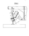
- Figures 1 to 4 are partially sectional views of four embodiments of the device according to the invention.
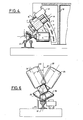
- FIG. 5 illustrates, seen from the side, a group of two grinding devices according to a fifth embodiment, mounted on a guide carriage of a railway vehicle.
- FIG. 6 is a schematic section along the line V-V of FIG. 5.
- FIG. 7 is an overall view illustrating the mounting on a reprofiling vehicle of the rail in the process of the grinding device illustrated in FIGS. 5 and 6.
- Figure 1 schematically illustrates a first embodiment of the grinding device according to the invention.
- This grinding device comprises a grinding wheel 1, the peripheral surface of which has the shape of a surface of revolution, here a concave surface of revolution.
- This bell wheel 1 is fixed on an axis 2 of an electric drive motor 3.
- the carcass of the motor 3 comprises an extension 3a pivoted on a support 8 fixed in a known manner to a guide carriage of a railway vehicle (not illustrated) but which may be of the type of carriages 6,7 of the device described in patent DE- AS-2.701.216).
- a jack 5 is articulated on the support 8 on the one hand and on the other hand, by the rod 6a of its piston on an ear 3b of the carcass of the motor 3.
- the grinding wheel is in contact with the rail 12 by its front planar face and its advance travel, compensating for its wear and defining its cutting depth, takes place in an arc under the effect of the jack 5.
- This direction d the feed is substantially parallel to the generator g of the grinding wheel in the vicinity of its point of contact with the rail 12.
- the size of the wheel, in the vicinity of the rail, defined by its front face and its generatrix g is always the same whatever the advance of the wheel. Thanks to this arrangement, this grinding wheel can never come into contact with obstacles, counter-rail, signaling boxes, etc., located along the track near the rail to be reprofiled.
- the peripheral surface of the grinding wheel has a generator in an arc and the advance movement of the grinding wheel takes place along a substantially identical radius R.
- peripheral surface of the grinding wheel may have curvilinear, non-circular generators, in this case the means for advancing the grinding wheel must be designed to move the latter substantially parallel to its generator in the vicinity of the point of contact with the rail.
- peripheral surface of revolution of the grinding wheel could be convex.
- the grinding wheel is conical, its peripheral surface of revolution being a truncated cone, which makes it possible to provide a rectilinear advance travel of the grinding wheel, substantially parallel to its generatrix. in the vicinity of the point of contact with the rail.
- the grinding device comprises a conical bell or lapidary wheel 1, that is to say the peripheral surface of which is constituted by a truncated cone.
- This conical grinding wheel 1 is fixed to the axis 2 of an electric drive motor 3.
- the active working surface of the grinding wheel is flat and perpendicular to the axis of symmetry and rotation of the grinding wheel 1.
- the drive motor 3 is rigidly fixed to a gusset 4 secured to the chamber 5 of a double-acting cylinder whose piston 6 is secured to a guide column 7 passing right through the chamber 5.
- This column guide 7 is secured to a support 8 fixed with bolts 9 to a carriage 10 of a railway vehicle. Due to the lights 11 of the support 8 it can be fixed on the carriage 10 according to several orientations so as to vary the position of the grinding wheel 1 relative to the rail 12 according to the part of the head of the rail that is to be reprofiled .
- the guide column 7 is provided with conduits 13, 14 opening on one side and the other of the piston 6 in the chamber 5 of the hydraulic or pneumatic cylinder 5, 6.
- the angle included between the axis of the jack 5, 6 causing the advance movement of the grinding wheel 1, displacement defining the depth of cutting and compensating for the wear of the grinding wheel, and the axis of rotation of the grinding wheel 1 is of the order of 30 °. This angle can be chosen within very wide limits depending on the portion of the rail to be reprofiled.
- this angle ⁇ is substantially equal to half the angle at the apex a of the conical grinding wheel 1, so that the direction of advance of the grinding wheel 1 towards the rail 12 is substantially parallel to the external generator. the grinding wheel in the vicinity of the point of contact of the latter with the rail.
- the grinding device is positioned relative to the track so that a counter rail, a signaling box or any other obstacle located along the track is outside the zone in which the grinding wheel moves during the advance of the vehicle along the track.
- the axis of rotation of the grinding wheel 1 forms an angle ⁇ with the direction of advance of this grinding wheel defined by the axis of the jack 5, 6, 7.
- the front working surface of the grinding wheel 1 is of frustoconical shape and intersects the peripheral surface of the grinding wheel, also tapered, approximately at right angles.
- This arrangement is particularly advantageous for reprofiling the upper running surface of the rail 12. It is seen that thanks to this arrangement this upper running surface of the rail can be reprofiled even at level crossings where the rail 12 is practically buried in the roadway.
- angle f between the axis of rotation of the grinding wheel and the direction of advance of the latter, namely the axis of the jack 5, 6, 7, is substantially equal to half the angle at apex a of the conical grinding wheel 1 and the advancement of the grinding wheel takes place substantially parallel to its generator in the vicinity of its point of contact with the rail.
- the support 8 can in this embodiment be mounted on the carriage as illustrated for example in Figure 1. Thus, it is possible to tilt the grinding wheel relative to the rail to be reprofiled according to the portion of the rolling table to be reprofiled.
- Figure 4 illustrates an embodiment of the grinding device used for reprofiling the lateral face of the rail head.
- the conical wheel 1 is rotated by the motor 3 along a horizontal axis.
- the gusset 4 secured to the motor 3 slides on two bars 15 secured to the support 8.
- a lug of the gusset 4 is articulated on the rod 16 of a double-acting cylinder 17 controlling the advance travel of the grinding wheel 1.
- the direction of advance of the grinding wheel 1, parallel to the rods 15, forms an angle ⁇ with the axis of rotation of the grinding wheel 1 and is substantially parallel to the generator of the grinding wheel in the vicinity of its point of contact with the rail.
- This angle has been chosen here substantially equal to 45 ° and the angle at the top of the grinding wheel 1 is approximately equal to 90 °.
- the support 8 can be moved angularly relative to the tool carriage 10 to allow grinding different portions of the surface of the rail head.
- This movement is a rotation around an axis parallel to the rail, in the examples illustrated around a fictitious axis located inside the rail, more precisely the head of the rail.
- This movement does not modify the angle between the direction of advance of the grinding wheel and its axis of rotation but allows the direction in which the grinding wheel is moved relative to the rail to be adjusted.
- FIG. 7 illustrates a railway vehicle for reprofiling the rails of a railway track provided with two tool-carrying carriages 18, 19, rolling on the rail using flanged wheels 20, connected to the chassis of the vehicle on the one hand by drive links 21, 22 of the carriage along the rail and on the other hand by articulated links comprising jacks 23, 24 making it possible to move the carriage vertically relative to the chassis of the vehicle and also allowing d 'apply the carriages against the rail 12 with a determined force.
- each carriage carries two grinding devices each having two working units formed by a drive motor 25 and a conical grinding wheel 26.
- the two working units of the same grinding device are rigidly connected together by a support 27.
- levers forming a deformable parallelogram The connection of this support 27 to the carriage 18 is carried out using levers forming a deformable parallelogram.
- Two parallel levers 28, 29 are pivoted at one of their ends on the carriage at 30, 31 respectively.
- the free end of the lever 28 is pivoted at 32 on one of the ends of a connecting rod 33, the other end of which is pivoted on the support 27.
- the free end of the lever 29 is pivoted at 34 on the connecting rod 33.
- the distances between the pivot points 30, 31 and 32, 34 as well as the pivot points 30, 32 and 31, 34 are respectively equal so as to form a deformable parallelogram.
- the connecting rod 33 extends vertically like the line connecting the pivot points 30 and 31.
- the end of the lever 28 pivoted on the carriage includes an ear 35 articulated on the housing of a double-acting cylinder 36 whose rod 37, integral with the piston, is pivoted on an ear 38 which has the end of the pivoted lever 29 on the connecting rod 33.
- the axis of rotation of the grinding wheels 26 is not confused with the direction of advance of these grinding wheels, controlled by the connecting rod 33, but forms an angle with respect to this direction. This angle can be adjusted by modifying the angular position of each working unit relative to the support 27.
- the entire parallelogram device described above can be pivoted around axes 39 in order to be able to orient the advance movement of the grinding wheels as a function of the area of the rail profile to be ground.
- FIG. 6 is a partial and schematic view along the line VV of Figure 5.
- each motor unit 25 - grinding wheel 26 is adjusted with another inclination relative to the rail so as to reprofile different portions of the surface of the head of the rail.
- the pivoting which the motor unit 25 - grinding wheel 26 can carry out relative to the support 27 is preferably carried out in an arc centered on a fictitious axis parallel to the rail 12, that is to say in the direction of movement of the vehicle, this fictitious axis being located in the rail.
- the units can be inclined either inside the track with an angle f, or outside the track with the angle il without interfering with the obstacles located along the track .
- the grinding wheel takes an inclined position and its lower peripheral part re is in contact with the rail.
- Most of the grinding wheel is located above the rail outside the area occupied by obstacles. Thanks to this arrangement, we are able to keep the grinding stones working against the rail permanently even when passing obstacles such as level crossings, signal boxes, counter-rails, etc., which saves appreciable time, ensures high reprofiling precision and above all regular grinding since the grinding wheels are always in contact with the rail.
- the size of the wheel relative to obstacles remains the same regardless of the advance of the wheel.
Landscapes
- Engineering & Computer Science (AREA)
- Mechanical Engineering (AREA)
- Architecture (AREA)
- Civil Engineering (AREA)
- Structural Engineering (AREA)
- Machines For Laying And Maintaining Railways (AREA)
- Grinding Of Cylindrical And Plane Surfaces (AREA)
- Polishing Bodies And Polishing Tools (AREA)
Priority Applications (1)
| Application Number | Priority Date | Filing Date | Title |
|---|---|---|---|
| AT81105139T ATE6278T1 (de) | 1980-07-23 | 1981-07-02 | Schleifvorrichtung zum profilieren einer eisenbahnschiene. |
Applications Claiming Priority (2)
| Application Number | Priority Date | Filing Date | Title |
|---|---|---|---|
| CH5331/80 | 1980-07-23 | ||
| CH533180A CH626673A5 (de) | 1980-07-23 | 1980-07-23 |
Publications (2)
| Publication Number | Publication Date |
|---|---|
| EP0044964A1 true EP0044964A1 (de) | 1982-02-03 |
| EP0044964B1 EP0044964B1 (de) | 1984-02-15 |
Family
ID=4291796
Family Applications (1)
| Application Number | Title | Priority Date | Filing Date |
|---|---|---|---|
| EP81105139A Expired EP0044964B1 (de) | 1980-07-23 | 1981-07-02 | Schleifvorrichtung zum Profilieren einer Eisenbahnschiene |
Country Status (9)
| Country | Link |
|---|---|
| US (1) | US4492059A (de) |
| EP (1) | EP0044964B1 (de) |
| JP (1) | JPS5751303A (de) |
| AT (1) | ATE6278T1 (de) |
| AU (1) | AU542549B2 (de) |
| CA (1) | CA1167647A (de) |
| CH (1) | CH626673A5 (de) |
| DE (1) | DE3162282D1 (de) |
| ZA (1) | ZA814616B (de) |
Cited By (1)
| Publication number | Priority date | Publication date | Assignee | Title |
|---|---|---|---|---|
| FR2557488A1 (fr) * | 1983-12-28 | 1985-07-05 | Geismar Anc Ets L | Machine a reprofiler les rails uses |
Families Citing this family (31)
| Publication number | Priority date | Publication date | Assignee | Title |
|---|---|---|---|---|
| DE3307456A1 (de) * | 1983-03-03 | 1984-09-06 | Deutsche Gesellschaft für Wiederaufarbeitung von Kernbrennstoffen mbH, 3000 Hannover | Hantierungsvorrichtung zum fernbedienten arbeiten mit betriebsmitteln |
| CH655528B (de) * | 1984-02-06 | 1986-04-30 | ||
| US4779384A (en) * | 1986-02-13 | 1988-10-25 | Harsco Corporation | Rail grinder |
| US4862647A (en) * | 1987-08-31 | 1989-09-05 | Loram Maintenance Of Way, Inc. | Rail grinding machine |
| US4829723A (en) * | 1987-10-16 | 1989-05-16 | Loram Maintenance Of Way, Inc. | Rail grinding machine |
| JPH02152336A (ja) * | 1988-12-05 | 1990-06-12 | Nec Corp | ディジタル多重化器 |
| CH678341A5 (de) * | 1989-03-02 | 1991-08-30 | Speno International | |
| US5185959A (en) * | 1990-03-29 | 1993-02-16 | Tamglass Oy | Apparatus for grinding the edge of a glass sheet |
| US5359815A (en) * | 1992-11-06 | 1994-11-01 | Harsco Corporation | Profile grinder |
| EP0665332B1 (de) * | 1994-02-01 | 1998-04-15 | Franz Plasser Bahnbaumaschinen-Industriegesellschaft m.b.H. | Einrichtung zum Schleifen von Schienen |
| CH690963A5 (fr) * | 1996-12-20 | 2001-03-15 | Speno Internat S A | Dispositif pour la finition du reprofilage en voie et en continu de la surface du champignon d'au moins un rail d'une voie ferrée. |
| US6033291A (en) * | 1998-03-16 | 2000-03-07 | Loram Maintenance Of Way, Inc. | Offset rail grinding |
| US6033166A (en) * | 1998-08-27 | 2000-03-07 | Koppers Industries, Inc. | Rail milling machine |
| ATE450654T1 (de) * | 2001-10-25 | 2009-12-15 | Loram Maintenance Of Way | Verfahren und vorrichtung zum ununterbrochenen schleifen von bahnübergangs- und hauptgleisen |
| US7442115B1 (en) * | 2003-05-15 | 2008-10-28 | Racine Railroad Products, Inc. | Railway grinder |
| US6953386B1 (en) | 2004-07-19 | 2005-10-11 | Railworks Corporation | Active spark control |
| US6981907B1 (en) * | 2004-11-03 | 2006-01-03 | Railworks Corporation | High angle grinder |
| JP4649288B2 (ja) * | 2005-08-05 | 2011-03-09 | 保線機器整備株式会社 | 路面電車の溝付きレールの摩耗部補修個所の削正装置 |
| USD651223S1 (en) * | 2006-06-23 | 2011-12-27 | Kennametal Inc. | Machining insert for the initial machining and/or the reprofiling of at least one wheel of a vehicle that runs on rails, and for the initial machining and/or the reprofiling of a disc of a disc brake for atleast one wheel of a vehicle that runs on rails |
| US8353278B2 (en) * | 2009-07-22 | 2013-01-15 | C.M.S.-North America, Inc. | Rotary stone cutting tool |
| AT510566B1 (de) * | 2010-11-11 | 2012-05-15 | Linsinger Maschinenbau Gesellschaft M B H | Verfahren zum profilieren einer verlegten schiene und bearbeitungsfahrzeug |
| US8587939B2 (en) | 2011-01-31 | 2013-11-19 | Apple Inc. | Handheld portable device |
| US8665160B2 (en) | 2011-01-31 | 2014-03-04 | Apple Inc. | Antenna, shielding and grounding |
| US8911280B2 (en) * | 2011-01-31 | 2014-12-16 | Apple Inc. | Apparatus for shaping exterior surface of a metal alloy casing |
| JP5845477B2 (ja) * | 2011-10-25 | 2016-01-20 | 東日本旅客鉄道株式会社 | レール削正装置 |
| BR112016008836B1 (pt) * | 2013-10-21 | 2022-07-19 | Harsco Technologies Llc. | Método para a determinação de uma operação de moagem de motores de moagem em um veículo de moagem e veículo de moagem de trilho |
| JP6667100B2 (ja) * | 2015-12-14 | 2020-03-18 | 株式会社ジェイテクト | ツルア、これを備えたツルーイング装置、研削装置及びツルーイング方法 |
| CN105463960B (zh) * | 2015-12-22 | 2017-01-18 | 常州市瑞泰工程机械有限公司 | 钢轨轨腰打磨除锈机 |
| JP6613292B2 (ja) * | 2017-11-30 | 2019-11-27 | 有限会社明石軌道 | レール削正装置 |
| EP3844344A4 (de) | 2018-08-27 | 2022-08-03 | Harsco Technologies LLC | Schienenfräsfahrzeug |
| CN113174790B (zh) * | 2021-04-26 | 2022-10-04 | 株洲时代电子技术有限公司 | 一种钢轨复合打磨方法 |
Citations (5)
| Publication number | Priority date | Publication date | Assignee | Title |
|---|---|---|---|---|
| DE1141305B (de) * | 1958-08-07 | 1962-12-20 | Elektro Thermit Gmbh | Schienenschleifvorrichtung zum Schleifen der Koepfe von Herzstuecken od. dgl. |
| DE2263958A1 (de) * | 1972-12-29 | 1974-07-04 | Elektro Thermit Gmbh | Vorrichtung zum profilgerechten bearbeiten von aufgeschweissten schienen |
| US3823455A (en) * | 1972-11-09 | 1974-07-16 | Racine Railroad Prod Inc | Rail polishing machine |
| US3945152A (en) * | 1974-03-06 | 1976-03-23 | Heinrich Helgemeir | Rail head re-form grinding machine |
| DE2612174A1 (de) * | 1975-12-01 | 1977-06-08 | Plasser Bahnbaumasch Franz | Schienenschleifmaschine |
Family Cites Families (5)
| Publication number | Priority date | Publication date | Assignee | Title |
|---|---|---|---|---|
| US3358406A (en) * | 1965-10-14 | 1967-12-19 | Speno International | Rail grinder |
| US3593465A (en) * | 1968-04-01 | 1971-07-20 | James A Krippes | Concrete rail grinder |
| US3908317A (en) * | 1971-08-09 | 1975-09-30 | Lester N Hambrick | Rail base grinding apparatus |
| US3945142A (en) * | 1974-08-02 | 1976-03-23 | Carl Walther, Sportwaffenfabrik | Mount for a sight on firearms |
| CH625848A5 (de) * | 1979-12-31 | 1981-10-15 | Speno International |
-
1980
- 1980-07-23 CH CH533180A patent/CH626673A5/fr not_active IP Right Cessation
-
1981
- 1981-07-02 DE DE8181105139T patent/DE3162282D1/de not_active Expired
- 1981-07-02 EP EP81105139A patent/EP0044964B1/de not_active Expired
- 1981-07-02 AT AT81105139T patent/ATE6278T1/de active
- 1981-07-08 ZA ZA814616A patent/ZA814616B/xx unknown
- 1981-07-22 AU AU73303/81A patent/AU542549B2/en not_active Ceased
- 1981-07-22 CA CA000382287A patent/CA1167647A/en not_active Expired
- 1981-07-23 JP JP56114517A patent/JPS5751303A/ja active Granted
-
1983
- 1983-12-12 US US06/560,262 patent/US4492059A/en not_active Expired - Fee Related
Patent Citations (5)
| Publication number | Priority date | Publication date | Assignee | Title |
|---|---|---|---|---|
| DE1141305B (de) * | 1958-08-07 | 1962-12-20 | Elektro Thermit Gmbh | Schienenschleifvorrichtung zum Schleifen der Koepfe von Herzstuecken od. dgl. |
| US3823455A (en) * | 1972-11-09 | 1974-07-16 | Racine Railroad Prod Inc | Rail polishing machine |
| DE2263958A1 (de) * | 1972-12-29 | 1974-07-04 | Elektro Thermit Gmbh | Vorrichtung zum profilgerechten bearbeiten von aufgeschweissten schienen |
| US3945152A (en) * | 1974-03-06 | 1976-03-23 | Heinrich Helgemeir | Rail head re-form grinding machine |
| DE2612174A1 (de) * | 1975-12-01 | 1977-06-08 | Plasser Bahnbaumasch Franz | Schienenschleifmaschine |
Cited By (2)
| Publication number | Priority date | Publication date | Assignee | Title |
|---|---|---|---|---|
| FR2557488A1 (fr) * | 1983-12-28 | 1985-07-05 | Geismar Anc Ets L | Machine a reprofiler les rails uses |
| EP0148089A3 (de) * | 1983-12-28 | 1985-08-28 | Societe Des Anciens Etablissements L. Geismar | Herprofilierungsmaschine für abgenutzte Schienen |
Also Published As
| Publication number | Publication date |
|---|---|
| EP0044964B1 (de) | 1984-02-15 |
| US4492059A (en) | 1985-01-08 |
| DE3162282D1 (en) | 1984-03-22 |
| JPS5751303A (en) | 1982-03-26 |
| ATE6278T1 (de) | 1984-03-15 |
| CH626673A5 (de) | 1981-11-30 |
| CA1167647A (en) | 1984-05-22 |
| AU7330381A (en) | 1982-01-28 |
| AU542549B2 (en) | 1985-02-28 |
| JPH0133603B2 (de) | 1989-07-14 |
| ZA814616B (en) | 1982-07-28 |
Similar Documents
| Publication | Publication Date | Title |
|---|---|---|
| EP0044964B1 (de) | Schleifvorrichtung zum Profilieren einer Eisenbahnschiene | |
| EP0154777B1 (de) | Schienenkopf-Wiederprofilierungsmaschine auf der Strecke für mindestens eine Schiene einer Eisenbahn | |
| NL1011620C2 (nl) | Stobbenfrees, alsmede werkwijze voor het bedrijven daarvan. | |
| EP0330842B1 (de) | Einrichtung zum Reprofilieren eines Gleises | |
| EP0145919B1 (de) | Vorrichtung zum kontinuierlichen Reprofilieren des Schienenkopfes an mindestens einer Schiene | |
| EP0501183B1 (de) | Vorrichtung zur Wiederprofilierung von Eisenbahnschienen | |
| FR2463230A1 (fr) | Machine de traitement de la surface des champignons des rails d'une voie ferree posee | |
| CH678341A5 (de) | ||
| CA1135563A (fr) | Bourreuse de voies ferrees | |
| EP0017520B1 (de) | Vorrichtung zum Ausrichten und Halten von zwei zu verschweissenden Schienenenden | |
| FR2667628A1 (fr) | Machine roulante de traitement de voie ferree, en particulier machine de bourrage, de levage et de dressage de voie ferree pour la zone d'aiguillage et de croisement. | |
| CH652774A5 (fr) | Machine de chantier ferroviaire dont le chassis roulant est equipe d'un dispositif pour lever et riper une voie ferree. | |
| FR2695853A1 (fr) | Machine à fraiser, à surfacer et à polir à changement automatique d'outils et dispositif correspondant. | |
| FR2694720A1 (fr) | Dispositif et procédé automatique de fraisage et de polissage. | |
| EP2337897B1 (de) | Vorrichtung zur wartung von schienenwegen | |
| FR2719541A1 (fr) | Wagon de travail comportant une surface de travail. | |
| CA2216576A1 (fr) | Dispositif pour la finition du reprofilage en voie et en continu de la surface du champignon d'au moins un rail d'une voie ferree | |
| EP0593361B1 (de) | Verfahren und Vorrichtung zum Schleifen zweier stumpf aneinanderstossender Schienen | |
| EP2241171B1 (de) | Werkzeughalterungsvorrichtung zur Aufrechterhaltung der Werkzeuge in Arbeitsposition für adaptierbare Formen | |
| EP0016688B1 (de) | Stabilisierungsvorrichtung für eine drehende Diamantscheibe in einer Stein verarbeitenden Maschine | |
| FR2674330A1 (fr) | Dispositif de mise en position de rotors, notamment de roues de vehicules automobiles, sur des machines d'equilibrage. | |
| FR2719253A1 (fr) | Procédé et dispositif de découpe d'un bloc de pierre en vue de la réalisation de plaques de parement d'angles présentant la forme de dièdres d'angle au sommet (alpha) prédéterminé. | |
| CA2292725A1 (en) | Device for milling or enlarging the inside diameter or the inside contour of an earthwork | |
| EP0789108A1 (de) | Rollwagen mit Schleif- oder Bearbeitungswerkzeuge für die Lauffläche und das Pilzteil von Eisenbahnschienen | |
| FR2703084A1 (fr) | Machine de meulage de rails d'une voie ferrée. |
Legal Events
| Date | Code | Title | Description |
|---|---|---|---|
| PUAI | Public reference made under article 153(3) epc to a published international application that has entered the european phase |
Free format text: ORIGINAL CODE: 0009012 |
|
| ITCL | It: translation for ep claims filed |
Representative=s name: SOCIETA' ITALIANA BREVETTI S.P.A. |
|
| AK | Designated contracting states |
Designated state(s): AT BE DE FR GB IT NL SE |
|
| TCAT | At: translation of patent claims filed | ||
| TCNL | Nl: translation of patent claims filed | ||
| 17P | Request for examination filed |
Effective date: 19820222 |
|
| DET | De: translation of patent claims | ||
| ITF | It: translation for a ep patent filed | ||
| GRAA | (expected) grant |
Free format text: ORIGINAL CODE: 0009210 |
|
| AK | Designated contracting states |
Designated state(s): AT BE DE FR GB IT NL SE |
|
| REF | Corresponds to: |
Ref document number: 6278 Country of ref document: AT Date of ref document: 19840315 Kind code of ref document: T |
|
| REF | Corresponds to: |
Ref document number: 3162282 Country of ref document: DE Date of ref document: 19840322 |
|
| PLBE | No opposition filed within time limit |
Free format text: ORIGINAL CODE: 0009261 |
|
| STAA | Information on the status of an ep patent application or granted ep patent |
Free format text: STATUS: NO OPPOSITION FILED WITHIN TIME LIMIT |
|
| 26N | No opposition filed | ||
| PGFP | Annual fee paid to national office [announced via postgrant information from national office to epo] |
Ref country code: SE Payment date: 19900625 Year of fee payment: 10 |
|
| PGFP | Annual fee paid to national office [announced via postgrant information from national office to epo] |
Ref country code: BE Payment date: 19900627 Year of fee payment: 10 |
|
| PGFP | Annual fee paid to national office [announced via postgrant information from national office to epo] |
Ref country code: GB Payment date: 19900629 Year of fee payment: 10 Ref country code: FR Payment date: 19900629 Year of fee payment: 10 |
|
| PGFP | Annual fee paid to national office [announced via postgrant information from national office to epo] |
Ref country code: AT Payment date: 19900704 Year of fee payment: 10 |
|
| ITTA | It: last paid annual fee | ||
| PGFP | Annual fee paid to national office [announced via postgrant information from national office to epo] |
Ref country code: NL Payment date: 19900731 Year of fee payment: 10 |
|
| PGFP | Annual fee paid to national office [announced via postgrant information from national office to epo] |
Ref country code: DE Payment date: 19900802 Year of fee payment: 10 |
|
| PG25 | Lapsed in a contracting state [announced via postgrant information from national office to epo] |
Ref country code: GB Effective date: 19910702 Ref country code: AT Effective date: 19910702 |
|
| PG25 | Lapsed in a contracting state [announced via postgrant information from national office to epo] |
Ref country code: SE Effective date: 19910703 |
|
| PG25 | Lapsed in a contracting state [announced via postgrant information from national office to epo] |
Ref country code: BE Effective date: 19910731 |
|
| BERE | Be: lapsed |
Owner name: SPENO INTERNATIONAL S.A. Effective date: 19910731 |
|
| PG25 | Lapsed in a contracting state [announced via postgrant information from national office to epo] |
Ref country code: NL Effective date: 19920201 |
|
| GBPC | Gb: european patent ceased through non-payment of renewal fee | ||
| NLV4 | Nl: lapsed or anulled due to non-payment of the annual fee | ||
| PG25 | Lapsed in a contracting state [announced via postgrant information from national office to epo] |
Ref country code: FR Effective date: 19920331 |
|
| PG25 | Lapsed in a contracting state [announced via postgrant information from national office to epo] |
Ref country code: DE Effective date: 19920401 |
|
| REG | Reference to a national code |
Ref country code: FR Ref legal event code: ST |
|
| EUG | Se: european patent has lapsed |
Ref document number: 81105139.0 Effective date: 19920210 |