EP0045116B1 - Procédé pour éjecter un récipient embouti d'un poinçon de réétirage et poinçon de réétirage pour exécuter ce procédé - Google Patents
Procédé pour éjecter un récipient embouti d'un poinçon de réétirage et poinçon de réétirage pour exécuter ce procédé Download PDFInfo
- Publication number
- EP0045116B1 EP0045116B1 EP81200865A EP81200865A EP0045116B1 EP 0045116 B1 EP0045116 B1 EP 0045116B1 EP 81200865 A EP81200865 A EP 81200865A EP 81200865 A EP81200865 A EP 81200865A EP 0045116 B1 EP0045116 B1 EP 0045116B1
- Authority
- EP
- European Patent Office
- Prior art keywords
- wall
- mandril
- ironing
- sleeve
- fluid
- Prior art date
- Legal status (The legal status is an assumption and is not a legal conclusion. Google has not performed a legal analysis and makes no representation as to the accuracy of the status listed.)
- Expired
Links
- 238000010409 ironing Methods 0.000 title claims abstract description 33
- 238000000034 method Methods 0.000 title claims abstract description 18
- 239000012530 fluid Substances 0.000 claims abstract description 26
- 238000004891 communication Methods 0.000 claims description 2
- 239000000463 material Substances 0.000 description 5
- XEEYBQQBJWHFJM-UHFFFAOYSA-N Iron Chemical compound [Fe] XEEYBQQBJWHFJM-UHFFFAOYSA-N 0.000 description 4
- 230000000694 effects Effects 0.000 description 3
- 238000006073 displacement reaction Methods 0.000 description 2
- 229910052742 iron Inorganic materials 0.000 description 2
- 229910000831 Steel Inorganic materials 0.000 description 1
- 239000004035 construction material Substances 0.000 description 1
- 238000001816 cooling Methods 0.000 description 1
- 230000008878 coupling Effects 0.000 description 1
- 238000010168 coupling process Methods 0.000 description 1
- 238000005859 coupling reaction Methods 0.000 description 1
- 238000002474 experimental method Methods 0.000 description 1
- 238000010438 heat treatment Methods 0.000 description 1
- 238000004886 process control Methods 0.000 description 1
- 239000010959 steel Substances 0.000 description 1
Images
Classifications
-
- B—PERFORMING OPERATIONS; TRANSPORTING
- B21—MECHANICAL METAL-WORKING WITHOUT ESSENTIALLY REMOVING MATERIAL; PUNCHING METAL
- B21D—WORKING OR PROCESSING OF SHEET METAL OR METAL TUBES, RODS OR PROFILES WITHOUT ESSENTIALLY REMOVING MATERIAL; PUNCHING METAL
- B21D45/00—Ejecting or stripping-off devices arranged in machines or tools dealt with in this subclass
- B21D45/06—Stripping-off devices
Definitions
- the invention relates to a method of releasing a wall-ironed sleeve having an enlarged wall thickness at the end remote from the bottom from a wall-ironing mandril whereby pressurized fluid is led to the operative surface of the mandril causing the sleeve to be released from the mandril.
- a pressurized fluid is introduced at the front face of the wall-ironing mandril.
- a further disadvantage of the prior art is that the introduction of fluid at the front face of the wall-ironing mandril brings about the risk of bottom deformation as well as the risk of the sleeve being, so to say, shot away, which may give rise to unsatisfactory process control and to disturbances in automatic processes.
- the invention has for its object to obviate the disadvantages of the prior art and provides a method of the kind set forth in which the fluid is allowed to enter at the transitional region between the normal wall thickness and the enlarged wall thickness. It is pointed out that the axial position of the admission of the fluid corresponds to a region where no wall-ironing operation takes place, since otherwise fluid inlet apertures might become clogged, the fluid being now admitted as near as possible the zone where the operation concerned is carried out in order to maximize the effect.
- the fluid pressure preferably amounts to at least 10 bars.
- Experiments with tinned iron sleeves having a wall thickness of about 0.1 mm have shown that, for example, at a fluid pressure of about 25 bars the sleeve can be released substantially without friction.
- the invention furthermore relates to a wall-ironing mandril suitable for carrying into effect the method according to the invention, said mandril having a cylindrical, relatively broad part at its free end, a cylindrical, relatively narrow part coaxial to the former and a substantially conical part interconnecting said two cylindrical parts and at least one fluid inlet conduit opening out at the operative surface, said wall-ironing mandril being characterized in accordance with the invention in that the at least one fluid inlet conduit opens out in the region of the transitional part between the cylindrical, relatively narrow part and the conical part.
- a plurality of fluid inlet apertures are arranged along the circumference.
- At least one pressure equalizing duct opening out at the front face is preferably provided at least one pressure equalizing duct opening out at the front face. This excludes at the same time any risk of the atmospheric pressure between the front face of the mandril and the bottom of the sleeve deforming the sleeve bottom and the neighbouring wall parts.
- sleeves having wall thicknesses of even less than 0.1 mm can be stripped off the wall-ironing mandril without deformation of the material.
- an appreciable saving of material can be obtained by reducing length differences between the initially manufactured and the finally trimmed sleeves. Moreover, disturbances of the process are minimized, which is conductive to the productivity, whilst in addition the various tools have a considerably longer lifetime, which means saving of costs.
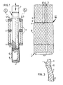
- the device schematically shown in Figure 1 comprises a wall-ironing mandril 1 embodying the invention, a first wall-ironing ring 2, a second wall-ironing ring 3, a third wall-ironing ring 4 as well as a frame 5 interconnecting the three wall-ironing rings.
- the wall-ironing mandril is axially driven by means of a plunger 7 actuated by means not shown and being rigidly connected by known coupling means with the wall-ironing mandril 1.
- the device is in that stage of the wall-ironing process in which a formed sleeve 6 has to be released from the wall-ironing mandril 1.
- the wall-ironing mandril has a plurality of circumferentially disposed fluid inlet apertures 8 located in the area of a transitional part shown in the drawing, particularly Figures 2 and 3, between the relatively narrow part 9 of the wall-ironing mandril 1 and the conical part 11 connecting the narrow part 9 with the relatively broad part 10 with a view to the releasing operation.
- the fluid inlet apertures 8 communicate in the manner illustrated in Figure 1 through a flexible pressure duct 12 with a source 13 of pressurized fluid.
- This pressurized fluid source is energized synchronously with the displacement of the plunger 7 or continuously in a manner such that the releasing operation takes place after the accomplishment of the wall-ironing operation proper.
- the wall-ironing mandril 1 has a fluid inlet aperture 14 which communicates in the manner shown in Figure 1 through a second pressure duct 15 with a second source 16 of pressurized fluid, for example, compressed air.
- This source is also energized synchronously with the displacement of the plunger 7 or else permanently.
- the axial positions of the apertures 8 may be chosen within wide limits on either side.
Landscapes
- Engineering & Computer Science (AREA)
- Mechanical Engineering (AREA)
- Shaping Metal By Deep-Drawing, Or The Like (AREA)
- Processing And Handling Of Plastics And Other Materials For Molding In General (AREA)
- Forging (AREA)
- Containers Having Bodies Formed In One Piece (AREA)
- Metal Extraction Processes (AREA)
- Press Drives And Press Lines (AREA)
- Reciprocating Pumps (AREA)
Claims (6)
Priority Applications (1)
| Application Number | Priority Date | Filing Date | Title |
|---|---|---|---|
| AT81200865T ATE7275T1 (de) | 1980-07-30 | 1981-07-30 | Verfahren zum abstreifen tiefgezogener hohlkoerper von einem ziehdorn und ziehdorn zum ausfuehren dieses verfahrens. |
Applications Claiming Priority (2)
| Application Number | Priority Date | Filing Date | Title |
|---|---|---|---|
| NL8004357A NL8004357A (nl) | 1980-07-30 | 1980-07-30 | Werkwijze voor het vanaf een duntrekdoorn lossen van een dungetrokken bus en duntrekdoorn voor uitvoering van die werkwijze. |
| NL8004357 | 1980-07-30 |
Publications (2)
| Publication Number | Publication Date |
|---|---|
| EP0045116A1 EP0045116A1 (fr) | 1982-02-03 |
| EP0045116B1 true EP0045116B1 (fr) | 1984-05-02 |
Family
ID=19835683
Family Applications (1)
| Application Number | Title | Priority Date | Filing Date |
|---|---|---|---|
| EP81200865A Expired EP0045116B1 (fr) | 1980-07-30 | 1981-07-30 | Procédé pour éjecter un récipient embouti d'un poinçon de réétirage et poinçon de réétirage pour exécuter ce procédé |
Country Status (7)
| Country | Link |
|---|---|
| EP (1) | EP0045116B1 (fr) |
| JP (1) | JPS57115923A (fr) |
| AT (1) | ATE7275T1 (fr) |
| AU (1) | AU553560B2 (fr) |
| DE (1) | DE3163393D1 (fr) |
| NL (1) | NL8004357A (fr) |
| ZA (1) | ZA814567B (fr) |
Families Citing this family (2)
| Publication number | Priority date | Publication date | Assignee | Title |
|---|---|---|---|---|
| GB9507204D0 (en) * | 1995-04-07 | 1995-05-31 | Metal Box Plc | Base forming of can bodies |
| JP6032750B2 (ja) * | 2013-10-18 | 2016-11-30 | 旭精機工業株式会社 | パンチ及びプレス成形機 |
Family Cites Families (5)
| Publication number | Priority date | Publication date | Assignee | Title |
|---|---|---|---|---|
| US3402591A (en) * | 1964-10-28 | 1968-09-24 | Reynolds Metals Co | Apparatus for making drawn and ironed cans or containers |
| US3406554A (en) * | 1965-07-06 | 1968-10-22 | Continental Can Co | Apparatus for and method of forming containers |
| US3524338A (en) * | 1968-02-05 | 1970-08-18 | Continental Can Co | Stripping punch |
| JPS5129323Y2 (fr) * | 1971-01-28 | 1976-07-23 | ||
| US3771344A (en) * | 1972-10-30 | 1973-11-13 | Crown Cork & Seal Co | Apparatus for stripping container bodies from metal working punches |
-
1980
- 1980-07-30 NL NL8004357A patent/NL8004357A/nl not_active Application Discontinuation
-
1981
- 1981-07-06 ZA ZA814567A patent/ZA814567B/xx unknown
- 1981-07-24 JP JP56117020A patent/JPS57115923A/ja active Granted
- 1981-07-27 AU AU73472/81A patent/AU553560B2/en not_active Ceased
- 1981-07-30 DE DE8181200865T patent/DE3163393D1/de not_active Expired
- 1981-07-30 AT AT81200865T patent/ATE7275T1/de not_active IP Right Cessation
- 1981-07-30 EP EP81200865A patent/EP0045116B1/fr not_active Expired
Also Published As
| Publication number | Publication date |
|---|---|
| ZA814567B (en) | 1982-07-28 |
| AU7347281A (en) | 1982-02-04 |
| EP0045116A1 (fr) | 1982-02-03 |
| AU553560B2 (en) | 1986-07-24 |
| DE3163393D1 (en) | 1984-06-07 |
| JPS57115923A (en) | 1982-07-19 |
| NL8004357A (nl) | 1982-03-01 |
| ATE7275T1 (de) | 1984-05-15 |
| JPH0116573B2 (fr) | 1989-03-24 |
Similar Documents
| Publication | Publication Date | Title |
|---|---|---|
| EP1008404B1 (fr) | Procede pour soumettre a un etirage de paroi les cannelures d'une tole metallique comprimee a decrochement | |
| US5901598A (en) | Method and apparatus for ejecting sheet metal parts from a press | |
| EP1175976A3 (fr) | Appareil pour découper des fenêtres dans des enveloppes | |
| GB2279602A (en) | Hollow body cut out | |
| EP0237128B1 (fr) | Procédé de formation d'une rainure dans une pièce tubulaire | |
| US4373368A (en) | Hydraulic assist stripping | |
| CA2355343A1 (fr) | Outil de pose de rivets | |
| EP1155956A3 (fr) | Système de propulsion à fluide permettant d'accélérer un fluide et d'ajuster sa direction | |
| EP0045116B1 (fr) | Procédé pour éjecter un récipient embouti d'un poinçon de réétirage et poinçon de réétirage pour exécuter ce procédé | |
| AU1153799A (en) | Mechanical assembly process and device | |
| AU625610B2 (en) | Pipe connection system | |
| EP1214991A3 (fr) | Dispositif pour la mise sous contrainte des corps extrudés ou emboutis | |
| US5108478A (en) | Methods of and apparatus for the further processing of gobs of glass | |
| US4305540A (en) | Adhesive dispersing anvil and method of using | |
| US4162570A (en) | Method and apparatus for separating a fitting from a tube | |
| AU6120699A (en) | Multifunction insert press | |
| JPS5662626A (en) | Pressing device simultaneously performing part working and conveying and positioning | |
| AU694483B2 (en) | A method and an arrangement for closing of at least one end of a tube and a plug for said closing | |
| US4043163A (en) | Device for removing the press rest from the front side of a disc for extruding tubes | |
| SU845961A1 (ru) | Устройство дл формообразовани дЕТАлЕй | |
| EP1036607A3 (fr) | Procédé et dispositif pour former une coupelle avec un fond profilé | |
| EP0891823A3 (fr) | Element de préhension pour un poinçon ou une matrice d'une machine à poinçonner | |
| CA2268862A1 (fr) | Appareil et procede destines a mettre en fusion du metal | |
| SU946979A1 (ru) | Термический пресс | |
| SE451365B (sv) | Sett och anordning for tillverkning av en reflektor till en parabolantenn |
Legal Events
| Date | Code | Title | Description |
|---|---|---|---|
| PUAI | Public reference made under article 153(3) epc to a published international application that has entered the european phase |
Free format text: ORIGINAL CODE: 0009012 |
|
| AK | Designated contracting states |
Designated state(s): AT BE CH DE FR GB IT LU NL SE |
|
| 17P | Request for examination filed |
Effective date: 19820803 |
|
| ITF | It: translation for a ep patent filed | ||
| GRAA | (expected) grant |
Free format text: ORIGINAL CODE: 0009210 |
|
| AK | Designated contracting states |
Designated state(s): AT BE CH DE FR GB IT LI LU NL SE |
|
| REF | Corresponds to: |
Ref document number: 7275 Country of ref document: AT Date of ref document: 19840515 Kind code of ref document: T |
|
| REF | Corresponds to: |
Ref document number: 3163393 Country of ref document: DE Date of ref document: 19840607 |
|
| ET | Fr: translation filed | ||
| PLBE | No opposition filed within time limit |
Free format text: ORIGINAL CODE: 0009261 |
|
| STAA | Information on the status of an ep patent application or granted ep patent |
Free format text: STATUS: NO OPPOSITION FILED WITHIN TIME LIMIT |
|
| 26N | No opposition filed | ||
| EPTA | Lu: last paid annual fee | ||
| ITTA | It: last paid annual fee | ||
| EAL | Se: european patent in force in sweden |
Ref document number: 81200865.4 |
|
| PGFP | Annual fee paid to national office [announced via postgrant information from national office to epo] |
Ref country code: FR Payment date: 19990713 Year of fee payment: 19 |
|
| PGFP | Annual fee paid to national office [announced via postgrant information from national office to epo] |
Ref country code: SE Payment date: 19990715 Year of fee payment: 19 |
|
| PGFP | Annual fee paid to national office [announced via postgrant information from national office to epo] |
Ref country code: AT Payment date: 19990723 Year of fee payment: 19 |
|
| PGFP | Annual fee paid to national office [announced via postgrant information from national office to epo] |
Ref country code: DE Payment date: 19990729 Year of fee payment: 19 |
|
| PGFP | Annual fee paid to national office [announced via postgrant information from national office to epo] |
Ref country code: NL Payment date: 19990730 Year of fee payment: 19 |
|
| PGFP | Annual fee paid to national office [announced via postgrant information from national office to epo] |
Ref country code: GB Payment date: 19990802 Year of fee payment: 19 |
|
| PGFP | Annual fee paid to national office [announced via postgrant information from national office to epo] |
Ref country code: LU Payment date: 19990805 Year of fee payment: 19 |
|
| PGFP | Annual fee paid to national office [announced via postgrant information from national office to epo] |
Ref country code: BE Payment date: 19990816 Year of fee payment: 19 |
|
| PGFP | Annual fee paid to national office [announced via postgrant information from national office to epo] |
Ref country code: CH Payment date: 19991004 Year of fee payment: 19 |
|
| PG25 | Lapsed in a contracting state [announced via postgrant information from national office to epo] |
Ref country code: LU Free format text: LAPSE BECAUSE OF NON-PAYMENT OF DUE FEES Effective date: 20000730 Ref country code: GB Free format text: LAPSE BECAUSE OF NON-PAYMENT OF DUE FEES Effective date: 20000730 Ref country code: AT Free format text: LAPSE BECAUSE OF NON-PAYMENT OF DUE FEES Effective date: 20000730 |
|
| PG25 | Lapsed in a contracting state [announced via postgrant information from national office to epo] |
Ref country code: SE Free format text: LAPSE BECAUSE OF NON-PAYMENT OF DUE FEES Effective date: 20000731 Ref country code: LI Free format text: LAPSE BECAUSE OF NON-PAYMENT OF DUE FEES Effective date: 20000731 Ref country code: CH Free format text: LAPSE BECAUSE OF NON-PAYMENT OF DUE FEES Effective date: 20000731 Ref country code: BE Free format text: LAPSE BECAUSE OF NON-PAYMENT OF DUE FEES Effective date: 20000731 |
|
| BERE | Be: lapsed |
Owner name: THOMASSEN & DRIJVER-VERBLIFA N.V. Effective date: 20000731 |
|
| PG25 | Lapsed in a contracting state [announced via postgrant information from national office to epo] |
Ref country code: NL Free format text: LAPSE BECAUSE OF NON-PAYMENT OF DUE FEES Effective date: 20010201 |
|
| REG | Reference to a national code |
Ref country code: CH Ref legal event code: PL |
|
| EUG | Se: european patent has lapsed |
Ref document number: 81200865.4 |
|
| GBPC | Gb: european patent ceased through non-payment of renewal fee |
Effective date: 20000730 |
|
| PG25 | Lapsed in a contracting state [announced via postgrant information from national office to epo] |
Ref country code: FR Free format text: LAPSE BECAUSE OF NON-PAYMENT OF DUE FEES Effective date: 20010330 |
|
| NLV4 | Nl: lapsed or anulled due to non-payment of the annual fee |
Effective date: 20010201 |
|
| REG | Reference to a national code |
Ref country code: FR Ref legal event code: ST |
|
| PG25 | Lapsed in a contracting state [announced via postgrant information from national office to epo] |
Ref country code: DE Free format text: LAPSE BECAUSE OF NON-PAYMENT OF DUE FEES Effective date: 20010501 |