EP0045146A1 - Distributeur de gobelets - Google Patents
Distributeur de gobelets Download PDFInfo
- Publication number
- EP0045146A1 EP0045146A1 EP81303147A EP81303147A EP0045146A1 EP 0045146 A1 EP0045146 A1 EP 0045146A1 EP 81303147 A EP81303147 A EP 81303147A EP 81303147 A EP81303147 A EP 81303147A EP 0045146 A1 EP0045146 A1 EP 0045146A1
- Authority
- EP
- European Patent Office
- Prior art keywords
- cam
- stack
- dispenser
- cams
- cups
- Prior art date
- Legal status (The legal status is an assumption and is not a legal conclusion. Google has not performed a legal analysis and makes no representation as to the accuracy of the status listed.)
- Granted
Links
- 230000013011 mating Effects 0.000 description 2
- 239000004794 expanded polystyrene Substances 0.000 description 1
- 239000006260 foam Substances 0.000 description 1
Images

Classifications
-
- B—PERFORMING OPERATIONS; TRANSPORTING
- B65—CONVEYING; PACKING; STORING; HANDLING THIN OR FILAMENTARY MATERIAL
- B65B—MACHINES, APPARATUS OR DEVICES FOR, OR METHODS OF, PACKAGING ARTICLES OR MATERIALS; UNPACKING
- B65B43/00—Forming, feeding, opening or setting-up containers or receptacles in association with packaging
- B65B43/42—Feeding or positioning bags, boxes, or cartons in the distended, opened, or set-up state; Feeding preformed rigid containers, e.g. tins, capsules, glass tubes, glasses, to the packaging position; Locating containers or receptacles at the filling position; Supporting containers or receptacles during the filling operation
- B65B43/44—Feeding or positioning bags, boxes, or cartons in the distended, opened, or set-up state; Feeding preformed rigid containers, e.g. tins, capsules, glass tubes, glasses, to the packaging position; Locating containers or receptacles at the filling position; Supporting containers or receptacles during the filling operation from supply magazines
-
- B—PERFORMING OPERATIONS; TRANSPORTING
- B65—CONVEYING; PACKING; STORING; HANDLING THIN OR FILAMENTARY MATERIAL
- B65G—TRANSPORT OR STORAGE DEVICES, e.g. CONVEYORS FOR LOADING OR TIPPING, SHOP CONVEYOR SYSTEMS OR PNEUMATIC TUBE CONVEYORS
- B65G59/00—De-stacking of articles
- B65G59/10—De-stacking nested articles
- B65G59/107—De-stacking nested articles by means of rotary devices or endless elements
- B65G59/108—De-stacking nested articles by means of rotary devices or endless elements the axis of rotation being substantially parallel to the axis of the stack
-
- G—PHYSICS
- G07—CHECKING-DEVICES
- G07F—COIN-FREED OR LIKE APPARATUS
- G07F13/00—Coin-freed apparatus for controlling dispensing or fluids, semiliquids or granular material from reservoirs
- G07F13/10—Coin-freed apparatus for controlling dispensing or fluids, semiliquids or granular material from reservoirs with associated dispensing of containers, e.g. cups or other articles
Definitions
- the invention relates to a cup dispenser particularly for dispensing cups singly from a stack of cups which will normally be a vertical stack.
- the dispenser is of the sort in which a plurality of cams are spaced about a first axis (coaxial with the axis of the stack of cups) and drive means are provided for rotating the cams together, each about an associated axis parallel to the first axis.
- Each of the cams has a cam face which is a helix about its axis and is arranged to engage the rim of the end cup of a stack of cups located in the dispenser so that rotation of the cams in one direction pushes the end cup away from the remainder of the stack to dispense it.
- An object of the present invention is to provide a cam profile which provides a more satisfactory dispensing action and minimizes damage to the rim of a cup being dispensed.
- each cam is chamfered or radiused with respect to any diameter of the cam.
- the angle of chamfer is in a range 22° to 28° and with advantage substantially 25°.
- Such a cam profile is particularly suited for use with foam , and dispenses the cups without damaging their rims
- each cam also has an upwardly facing cam surface for engaging the next cup in the stack and holding up the stack as the lowermost cup is dispensed.
- this upwardly directed cam face is also chamfered with respect to any diameter, preferably the chamfer angle being in the range 19° to 26° and with advantage substantially 221 ⁇ 2°.
- the spiral angle of the helix of the dispensing cam face may be in the range 8° to 14 0 , preferably in the range 10° to 12° and with advantage substantially 11°.
- the effective length of the cam face extends through at least 270° around the cam and with advantage through over 300°.
- the dispenser preferably comprises a hollow casing in which the cam and drive, in the form of a ring gear, are mounted, with a central aperture in the top and bottom for receiving the stack of cups and dispensing them downwardly.
- the casing is made in top and bottom identical halves which are secured together by bolts or the like.
- the bolts can be additionally used to secure the casing to a mounting and the arrangement is such that the bolts can be inserted from either the top or the bottom to extend beyond either the bottom or top respectively for mounting to a surface either beneath or above the dispenser.
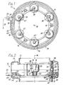
- the dispenser has a hollow casing 12 having identical upper and lower halves 13 and 14 respectively, connected together by three equiangularly spaced bolts 15.
- the dispenser has a vertical axis 16 and its top and bottom are effectively open and define coaxial bores 17 to locate a cup stacking tube (not shown) at the top and an outlet guide tube (not shown) at the bottom.
- Six cams 18 are mounted in the casing equiangularly spaced about the axis 16, the cams being angularly oscillatable about their own axes 19 by means of a common ring gear 20.
- the ring gear 20 is formed on its inner'periphery with teeth 21 which engage a pinion gear portion 22 of each of the cams.
- the ring gear 20 has an operating handle 23 which projects through an aperture 24 in" the casing and by means of which the ring gear can be reciprocated through an angle of 30° as indicated by the arrow 25.
- the ring gear is shown in one extreme position, the rest position, in Fig. 1 in which a flat upright surface 26 of each cam faces inwardly and surfaces 26 form together a hexagon and a support member 27 of each cam projects into the central space of the dispenser and engages under the lip of the lowermost cup to hold up the stack.
- Each cam has a cam projection 28 around its surface, the cam projection 28 having a helically formed downwardly facing dispensing surface 30 and an upwardly facing surface 31. These surfaces are both chamfered at an angle to any diameter of the cam, in this example the lower cam face 30 making an angle of 25 0 with such diameter and the upper cam face making an angle of 221 ⁇ 2° with such diameter.
- the cams are rotated together to enter the cam projections between the lips of the lowermost cup and the second lowermost cup as best seen in Fig. 3.
- the cups are made of expanded polystyrene. Further rotation of the cams pushes the lowermost cup downwardly away from the stack due to the helical form while the upper faces 31 continue to support the stack.
- the operating handle is then reciprocated back to its rest position in which the cam projections do not engage the cups which are supported on the members 27.
- the end of each member 27 is radiused as indicated at 32.
- the spiral angle of the helix indicated at 34 is 11 0 .
- Each of the halves of the casing are formed with six recesses and aligned pairs of recesses form bearing seats for the opposite projecting shaft portions 33 of the cams.
- the halves of the casing are each formed with a countersunk bore 36 opening to the outer (that is the upper or lower) surface, extending inwardly to a counter bore 37 of smaller diameter which in turn opens to the inner surface via a further bore 38 of diameter greater than bore 37.
- a ring dowel 40 is located in the aligned mating bores 38 and through this the bolt 15 passes.
- Each bolt can be inserted from either the top or the bottom with its head located in one of the bores 36 and a threaded member 40 located in the other bore 36 for mating with the bolt.
- the end 41 of the bolt then projects beyond one bore 36 and can be used for mounting the dispenser on its machine chassis or wall brackets.
- This arrangement allows the two casing halves to be made in the same mould and eliminates the need for a separate fixing means to mount the dispenser. It allows the dispenser to be mounted either to an upwardly or a downwardly facing surface.
Landscapes
- Physics & Mathematics (AREA)
- General Physics & Mathematics (AREA)
- Engineering & Computer Science (AREA)
- Mechanical Engineering (AREA)
- Beverage Vending Machines With Cups, And Gas Or Electricity Vending Machines (AREA)
- Polarising Elements (AREA)
- Telephone Function (AREA)
- Mechanical Treatment Of Semiconductor (AREA)
- De-Stacking Of Articles (AREA)
- Containers And Packaging Bodies Having A Special Means To Remove Contents (AREA)
- Stackable Containers (AREA)
- Magnetic Heads (AREA)
- Closures For Containers (AREA)
- Coating Apparatus (AREA)
Priority Applications (1)
| Application Number | Priority Date | Filing Date | Title |
|---|---|---|---|
| AT81303147T ATE17795T1 (de) | 1980-07-29 | 1981-07-10 | Becherabgabevorrichtung. |
Applications Claiming Priority (2)
| Application Number | Priority Date | Filing Date | Title |
|---|---|---|---|
| GB8024753 | 1980-07-29 | ||
| GB8024753A GB2081238B (en) | 1980-07-29 | 1980-07-29 | Cup dispenser |
Publications (2)
| Publication Number | Publication Date |
|---|---|
| EP0045146A1 true EP0045146A1 (fr) | 1982-02-03 |
| EP0045146B1 EP0045146B1 (fr) | 1986-01-29 |
Family
ID=10515105
Family Applications (1)
| Application Number | Title | Priority Date | Filing Date |
|---|---|---|---|
| EP81303147A Expired EP0045146B1 (fr) | 1980-07-29 | 1981-07-10 | Distributeur de gobelets |
Country Status (11)
| Country | Link |
|---|---|
| EP (1) | EP0045146B1 (fr) |
| AT (1) | ATE17795T1 (fr) |
| BE (1) | BE889751A (fr) |
| DE (2) | DE3173620D1 (fr) |
| DK (1) | DK336481A (fr) |
| ES (1) | ES504356A0 (fr) |
| FR (1) | FR2487658A3 (fr) |
| GB (1) | GB2081238B (fr) |
| IE (1) | IE52024B1 (fr) |
| IT (1) | IT1138892B (fr) |
| LU (1) | LU83515A1 (fr) |
Cited By (6)
| Publication number | Priority date | Publication date | Assignee | Title |
|---|---|---|---|---|
| WO1990006885A1 (fr) * | 1988-12-17 | 1990-06-28 | John Ernest Howard | Distributeur |
| EP0413654A1 (fr) * | 1989-06-16 | 1991-02-20 | Yarki S.A. | Distributeur de conteneurs |
| GB2394468A (en) * | 2002-10-25 | 2004-04-28 | Kwai Kun Wong | A rotatable cam element for dispensing stacked cups |
| WO2008141396A1 (fr) * | 2007-05-23 | 2008-11-27 | The Hot Chips Company | Appareil de distribution de gobelets |
| EP2914501A1 (fr) | 2012-11-02 | 2015-09-09 | Intech International A/S | Distributeur de plateaux et son utilisation |
| US11731844B2 (en) | 2020-05-19 | 2023-08-22 | Vemag Maschinenbau Gmbh | Apparatus and method for separating individual bowls from a stack of bowls |
Families Citing this family (2)
| Publication number | Priority date | Publication date | Assignee | Title |
|---|---|---|---|---|
| GB2224016A (en) * | 1988-10-05 | 1990-04-25 | Kwai Kun Wong | Nested cup separator |
| CN109677940A (zh) * | 2017-10-19 | 2019-04-26 | 比亚迪股份有限公司 | 一种分杯装置 |
Citations (8)
| Publication number | Priority date | Publication date | Assignee | Title |
|---|---|---|---|---|
| US1907713A (en) * | 1930-06-26 | 1933-05-09 | Kalix Cup Company | Container dispenser |
| FR1272145A (fr) * | 1960-08-11 | 1961-09-22 | Atwood Vacuum Machine Co | Appareil distributeur de gobelets ou objets analogues empilés |
| DE1148789B (de) * | 1955-09-01 | 1963-05-16 | American Can Co | Vorrichtung zur Sicherung gegen Beraubung an Selbstverkaeufern mit Abgabe von Papierbechern od. dgl. |
| GB1152414A (en) * | 1966-06-17 | 1969-05-21 | American Can Co | Cup Dispensing Apparatus |
| FR2176878A1 (fr) * | 1972-03-18 | 1973-11-02 | Mk Italiana Spa | |
| US3840150A (en) * | 1973-06-22 | 1974-10-08 | Phillips Petroleum Co | Separating and dispensing means for nested containers |
| US3932978A (en) * | 1973-06-15 | 1976-01-20 | Phillips Petroleum Company | Worm-type dispenser for rimmed containers |
| DE2519183A1 (de) * | 1975-04-30 | 1976-11-11 | Schwerdtel Ludwig Gmbh | Abstapel- und vereinzelungseinrichtung fuer stapelfaehige dosendeckel |
-
1980
- 1980-07-29 GB GB8024753A patent/GB2081238B/en not_active Expired
-
1981
- 1981-07-10 AT AT81303147T patent/ATE17795T1/de active
- 1981-07-10 EP EP81303147A patent/EP0045146B1/fr not_active Expired
- 1981-07-10 DE DE8181303147T patent/DE3173620D1/de not_active Expired
- 1981-07-24 FR FR8114457A patent/FR2487658A3/fr active Granted
- 1981-07-25 DE DE19818121849U patent/DE8121849U1/de not_active Expired
- 1981-07-27 BE BE0/205499A patent/BE889751A/fr not_active IP Right Cessation
- 1981-07-27 IE IE1689/81A patent/IE52024B1/en not_active IP Right Cessation
- 1981-07-28 LU LU83515A patent/LU83515A1/fr unknown
- 1981-07-28 DK DK336481A patent/DK336481A/da not_active Application Discontinuation
- 1981-07-28 ES ES504356A patent/ES504356A0/es active Granted
- 1981-07-29 IT IT23222/81A patent/IT1138892B/it active
Patent Citations (8)
| Publication number | Priority date | Publication date | Assignee | Title |
|---|---|---|---|---|
| US1907713A (en) * | 1930-06-26 | 1933-05-09 | Kalix Cup Company | Container dispenser |
| DE1148789B (de) * | 1955-09-01 | 1963-05-16 | American Can Co | Vorrichtung zur Sicherung gegen Beraubung an Selbstverkaeufern mit Abgabe von Papierbechern od. dgl. |
| FR1272145A (fr) * | 1960-08-11 | 1961-09-22 | Atwood Vacuum Machine Co | Appareil distributeur de gobelets ou objets analogues empilés |
| GB1152414A (en) * | 1966-06-17 | 1969-05-21 | American Can Co | Cup Dispensing Apparatus |
| FR2176878A1 (fr) * | 1972-03-18 | 1973-11-02 | Mk Italiana Spa | |
| US3932978A (en) * | 1973-06-15 | 1976-01-20 | Phillips Petroleum Company | Worm-type dispenser for rimmed containers |
| US3840150A (en) * | 1973-06-22 | 1974-10-08 | Phillips Petroleum Co | Separating and dispensing means for nested containers |
| DE2519183A1 (de) * | 1975-04-30 | 1976-11-11 | Schwerdtel Ludwig Gmbh | Abstapel- und vereinzelungseinrichtung fuer stapelfaehige dosendeckel |
Cited By (7)
| Publication number | Priority date | Publication date | Assignee | Title |
|---|---|---|---|---|
| WO1990006885A1 (fr) * | 1988-12-17 | 1990-06-28 | John Ernest Howard | Distributeur |
| EP0413654A1 (fr) * | 1989-06-16 | 1991-02-20 | Yarki S.A. | Distributeur de conteneurs |
| GB2394468A (en) * | 2002-10-25 | 2004-04-28 | Kwai Kun Wong | A rotatable cam element for dispensing stacked cups |
| GB2394468B (en) * | 2002-10-25 | 2005-10-19 | Kwai Kun Wong | Rotatable cam element |
| WO2008141396A1 (fr) * | 2007-05-23 | 2008-11-27 | The Hot Chips Company | Appareil de distribution de gobelets |
| EP2914501A1 (fr) | 2012-11-02 | 2015-09-09 | Intech International A/S | Distributeur de plateaux et son utilisation |
| US11731844B2 (en) | 2020-05-19 | 2023-08-22 | Vemag Maschinenbau Gmbh | Apparatus and method for separating individual bowls from a stack of bowls |
Also Published As
| Publication number | Publication date |
|---|---|
| ATE17795T1 (de) | 1986-02-15 |
| GB2081238A (en) | 1982-02-17 |
| EP0045146B1 (fr) | 1986-01-29 |
| DE8121849U1 (de) | 1982-01-07 |
| BE889751A (fr) | 1981-11-16 |
| FR2487658A3 (fr) | 1982-02-05 |
| IT1138892B (it) | 1986-09-17 |
| IT8123222A0 (it) | 1981-07-29 |
| GB2081238B (en) | 1984-11-21 |
| IE52024B1 (en) | 1987-05-27 |
| LU83515A1 (fr) | 1981-12-01 |
| FR2487658B3 (fr) | 1982-07-09 |
| IE811689L (en) | 1982-01-29 |
| DK336481A (da) | 1982-01-30 |
| ES8205176A1 (es) | 1982-06-01 |
| DE3173620D1 (en) | 1986-03-13 |
| ES504356A0 (es) | 1982-06-01 |
Similar Documents
| Publication | Publication Date | Title |
|---|---|---|
| US4852767A (en) | Vending machine dispenser | |
| EP0045146B1 (fr) | Distributeur de gobelets | |
| US5390714A (en) | cup locator for beverage dispenser | |
| US10679455B2 (en) | Item dispensing device | |
| US5074824A (en) | Coin hopper | |
| US4572404A (en) | Mechanism for cup dispenser | |
| CA1248062A (fr) | Debiteur de gobelets | |
| US4801290A (en) | Angular cap for centrifuges | |
| US3435987A (en) | Dispensing device with adjustable resilient outlet | |
| US20030024944A1 (en) | Curvy slide delivery chute in a machine for vending products | |
| US5064092A (en) | Device for an automatic dispensing of packaged products | |
| US2273783A (en) | Washer feeding device | |
| US6367611B1 (en) | Part feeding system | |
| JPS6095327A (ja) | 粉体を計量して容器に供給する機械 | |
| CA1180359A (fr) | Mecanisme pour robot debiteur de gobelets | |
| GB2394468A (en) | A rotatable cam element for dispensing stacked cups | |
| EP0541077B1 (fr) | Dispositif pour séparer et approvisionner des capsules ou fermetures similaires | |
| GB2184105A (en) | Rotary feeder | |
| JPH0248452B2 (fr) | ||
| CN220604083U (zh) | 一种自动售货机的多杯分配组件 | |
| EP1028400B1 (fr) | Mécanisme d'extraction pour machines automatiques de vente | |
| US2761585A (en) | Apparatus for orienting prismatic bodies | |
| SU1727976A1 (ru) | Устройство дл ориентации длинномерных деталей с не вно выраженным центром т жести | |
| US3032235A (en) | Dispenser container | |
| US20180186482A1 (en) | Storage container for drug portion storage and dispensing |
Legal Events
| Date | Code | Title | Description |
|---|---|---|---|
| PUAI | Public reference made under article 153(3) epc to a published international application that has entered the european phase |
Free format text: ORIGINAL CODE: 0009012 |
|
| AK | Designated contracting states |
Designated state(s): AT CH DE FR NL SE |
|
| 17P | Request for examination filed |
Effective date: 19820722 |
|
| GRAA | (expected) grant |
Free format text: ORIGINAL CODE: 0009210 |
|
| AK | Designated contracting states |
Designated state(s): AT CH DE FR LI NL SE |
|
| REF | Corresponds to: |
Ref document number: 17795 Country of ref document: AT Date of ref document: 19860215 Kind code of ref document: T |
|
| REF | Corresponds to: |
Ref document number: 3173620 Country of ref document: DE Date of ref document: 19860313 |
|
| ET | Fr: translation filed | ||
| PG25 | Lapsed in a contracting state [announced via postgrant information from national office to epo] |
Ref country code: AT Effective date: 19860710 |
|
| PG25 | Lapsed in a contracting state [announced via postgrant information from national office to epo] |
Ref country code: SE Effective date: 19860711 |
|
| PG25 | Lapsed in a contracting state [announced via postgrant information from national office to epo] |
Ref country code: LI Effective date: 19860731 Ref country code: CH Effective date: 19860731 |
|
| PLBE | No opposition filed within time limit |
Free format text: ORIGINAL CODE: 0009261 |
|
| STAA | Information on the status of an ep patent application or granted ep patent |
Free format text: STATUS: NO OPPOSITION FILED WITHIN TIME LIMIT |
|
| 26N | No opposition filed | ||
| PG25 | Lapsed in a contracting state [announced via postgrant information from national office to epo] |
Ref country code: NL Effective date: 19870201 |
|
| NLV4 | Nl: lapsed or anulled due to non-payment of the annual fee | ||
| REG | Reference to a national code |
Ref country code: CH Ref legal event code: PL |
|
| REG | Reference to a national code |
Ref country code: FR Ref legal event code: TP |
|
| PGFP | Annual fee paid to national office [announced via postgrant information from national office to epo] |
Ref country code: FR Payment date: 19930716 Year of fee payment: 13 |
|
| PGFP | Annual fee paid to national office [announced via postgrant information from national office to epo] |
Ref country code: DE Payment date: 19930821 Year of fee payment: 13 |
|
| EUG | Se: european patent has lapsed |
Ref document number: 81303147.3 Effective date: 19870609 |
|
| PG25 | Lapsed in a contracting state [announced via postgrant information from national office to epo] |
Ref country code: FR Effective date: 19950331 |
|
| PG25 | Lapsed in a contracting state [announced via postgrant information from national office to epo] |
Ref country code: DE Effective date: 19950401 |
|
| REG | Reference to a national code |
Ref country code: FR Ref legal event code: ST |