EP0045156A1 - Dispositif pour mesurer l'énergie d'un rayonnement - Google Patents
Dispositif pour mesurer l'énergie d'un rayonnement Download PDFInfo
- Publication number
- EP0045156A1 EP0045156A1 EP19810303229 EP81303229A EP0045156A1 EP 0045156 A1 EP0045156 A1 EP 0045156A1 EP 19810303229 EP19810303229 EP 19810303229 EP 81303229 A EP81303229 A EP 81303229A EP 0045156 A1 EP0045156 A1 EP 0045156A1
- Authority
- EP
- European Patent Office
- Prior art keywords
- radiation
- digital
- signals
- ratio
- values
- Prior art date
- Legal status (The legal status is an assumption and is not a legal conclusion. Google has not performed a legal analysis and makes no representation as to the accuracy of the status listed.)
- Granted
Links
- 230000005855 radiation Effects 0.000 title claims abstract description 109
- 238000005259 measurement Methods 0.000 title description 11
- 239000006096 absorbing agent Substances 0.000 claims abstract description 32
- 238000012545 processing Methods 0.000 claims description 10
- 238000010521 absorption reaction Methods 0.000 claims description 9
- 230000006870 function Effects 0.000 claims description 9
- 239000006100 radiation absorber Substances 0.000 claims description 4
- 238000000034 method Methods 0.000 abstract description 14
- 230000008569 process Effects 0.000 abstract description 5
- 230000000875 corresponding effect Effects 0.000 description 13
- 230000005540 biological transmission Effects 0.000 description 7
- 230000002596 correlated effect Effects 0.000 description 4
- 239000000523 sample Substances 0.000 description 4
- 230000001419 dependent effect Effects 0.000 description 3
- 239000000463 material Substances 0.000 description 3
- 230000000630 rising effect Effects 0.000 description 3
- 230000008859 change Effects 0.000 description 2
- 238000010586 diagram Methods 0.000 description 2
- 238000000691 measurement method Methods 0.000 description 2
- 230000001960 triggered effect Effects 0.000 description 2
- 230000004075 alteration Effects 0.000 description 1
- 230000006399 behavior Effects 0.000 description 1
- XQPRBTXUXXVTKB-UHFFFAOYSA-M caesium iodide Chemical compound [I-].[Cs+] XQPRBTXUXXVTKB-UHFFFAOYSA-M 0.000 description 1
- 238000006243 chemical reaction Methods 0.000 description 1
- 239000013078 crystal Substances 0.000 description 1
- 238000013480 data collection Methods 0.000 description 1
- 230000000881 depressing effect Effects 0.000 description 1
- 238000011161 development Methods 0.000 description 1
- 230000004069 differentiation Effects 0.000 description 1
- 230000036541 health Effects 0.000 description 1
- 238000009434 installation Methods 0.000 description 1
- 230000005865 ionizing radiation Effects 0.000 description 1
- 239000002245 particle Substances 0.000 description 1
- 230000035515 penetration Effects 0.000 description 1
- 230000008707 rearrangement Effects 0.000 description 1
- 230000001105 regulatory effect Effects 0.000 description 1
- 238000012552 review Methods 0.000 description 1
- 230000035939 shock Effects 0.000 description 1
- 239000007787 solid Substances 0.000 description 1
- 238000012546 transfer Methods 0.000 description 1
Images

Classifications
-
- H—ELECTRICITY
- H05—ELECTRIC TECHNIQUES NOT OTHERWISE PROVIDED FOR
- H05G—X-RAY TECHNIQUE
- H05G1/00—X-ray apparatus involving X-ray tubes; Circuits therefor
- H05G1/08—Electrical details
- H05G1/26—Measuring, controlling or protecting
-
- G—PHYSICS
- G01—MEASURING; TESTING
- G01T—MEASUREMENT OF NUCLEAR OR X-RADIATION
- G01T1/00—Measuring X-radiation, gamma radiation, corpuscular radiation, or cosmic radiation
- G01T1/36—Measuring spectral distribution of X-rays or of nuclear radiation spectrometry
-
- H—ELECTRICITY
- H05—ELECTRIC TECHNIQUES NOT OTHERWISE PROVIDED FOR
- H05G—X-RAY TECHNIQUE
- H05G1/00—X-ray apparatus involving X-ray tubes; Circuits therefor
- H05G1/08—Electrical details
- H05G1/26—Measuring, controlling or protecting
- H05G1/265—Measurements of current, voltage or power
Definitions
- the present invention relates to apparatus for analyzing radiation emitted by a radiation source, such as an X-ray tube, and more particularly to such apparatus which utilizes this radiation analysis to determine the magnitude of the electrical potential applied across the radiation source.
- the energy level of the emitted particles (generally photons) is of interest since it determines the penetration depth of the radiation, the hazard levels of persons exposed to the radiation, etc.
- the energy level of the radiation emitted by the radiation source is generally directly related to the electrical potential applied across the source. It has therefore been the practice to regulate the energy of the emitted radiation by regulating the magnitude of the potential applied to the radiation source.
- the voltage setting of an X-ray generator in terms of the peak voltage reached during the interval in which the X-ray source is energized.
- This voltage referred to as the peak kilovoltage or kVp
- the high voltage control for the X-ray generator is thus usually graduated in terms of kVp. It is desireable to occasionally verify the calibration of the high voltage control by comparing the actual applied kVp with the control setting which produced that reading. To do this it is of course necessary to determine the actual applied kVp.
- One method of accomplishing this is to directly measure the voltage appearing across the radiation source with a high voltage probe. Although simple in theory, this technique is quite difficult in practice due to the magnitude of this voltage (which may be well in excess of 50 kilovolts). Another technique involves an indirect measurement of the applied kVp through measurement of the peak energy of the radiation emanating from the radiation source.
- the measurement of kVp is complicated by the complexity of the waveform of the applied voltage.
- the voltage applied to the radiation source by the high voltage power supply will be strictly D.C., having no time varying components.
- the kVp and D.C. voltage are the same.
- the high voltage power supplies which are used to energize the radiation sources provide high voltage D.C. potentials having any number of different time varying components of varying magnitudes and frequencies. This is because, e.g., the amount of regulation provided in different high voltage supplies may differ, some power supplies may be operated from a single phase power line where others are operated from a three phase power line, etc. In these cases the kVp will differ by varying amounts from the D.C. voltage.
- the measurement technique must therefore either be capable of distinguishing kVp from D.C. or else include some means for inferring kVp from D.C. for a given X-ray unit.
- a device which includes a plurality of radiation detectors, each having an associated absorber disposed between it and the source of radiation.
- Analog peak detector circuits are connected to the output of the radiation detectors and detect the peak signals provided by the radiation detectors. The apparatus utilizes these signal peaks to provide a read out which is indicative of kVp.
- the X-ray radiation energy measurement apparatus of the present invention provides a means for measuring the peak energy of radiation emanating from a source, thereby indirectly measuring the kVp applied to the radiation source. It also permits analysis of other characteristics of the radiation energy and source potential.
- the apparatus is easy to use and avoids the high voltage generator loading, danger of shocks, etc., inherent in any direct measurement technique.
- the measurement derived by the unit is immediately available to the operator, unlike certain prior techniques wherein the measurement process took an extended period of time due to the need to, for example, develop film which had been exposed to the radiation.
- apparatus for determining the peak energy of radiation being emitted by a radiation source whose output of radiation energy varies with time.
- the apparatus includes at least two radiation detectors adapted to be disposed in the path of the radiation emitted by the radiation source, with each detector providing a respective analog signal having a value which varies in a known relation to the intensity of the radiation.
- a radiation absorber is associated with each of the detectors and is adapted to be disposed between the corresponding detector and the radiation source for absorbing a portion of the radiation emitted from the source.
- the absorbers have different radiation absorption values, and in each case a portion of the radiation absorbed by the absorber varies with the energy of the radiation.
- Means which is responsive to the first and second analog signals which are provided by the two radiation detectors for providing corresponding first and second digital signals, where each of the digital signals has digital values which represent and vary with a corresponding one of the analog signals.
- a digital memory is provided for storing digital values of each of the digital signals which occur at regular time intervals.
- processing means is provided for processing the stored digital value to determine the energy level of the radiation emitted from the radiation source.
- apparatus for analyzing radiation emitted by a radiation source whose output radiation energy varies with time.
- Radiation absorber means is included which is adapted to be illuminated by the radiation to be analyzed, including first and second absorber means having different absorption values.
- first and second radiation detector means are provided for detecting the portion of the radiation transmitted by the first and second absorber means, respectively, and for providing corresponding first and second electrical signals having values which vary in accordance with variations with time of the respectively detected radiation portion.
- the apparatus further includes means responsive to the first and second electrical signals for deriving a ratio signal which varies in accordance with the ratio of the first and second signals and which therefore varies in accordance with the time varying energy of the radiation and for processing the ratio signal to analyze the radiation emitted by the radiation source.
- the ratio of intensities of radiation passing through two different absorber thicknesses is generally directly indicative of the energy of the radiation illuminating the absorbers, and thus of the voltage applied to the radiation source.
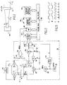
- a radiation source S (which may be an X-ray tube, for example), which is powered by a high voltage supply HV.
- the source S emits a beam of radiation having an intensity 1 0 .
- An absorber A is disposed in the path of the beam, and has a thickness "a". If the intensity of the beam on the leeward side of the absorber A is designated I 1 , then: Where I o , I, and "a" are as defined above and "u" is the energy-dependent absorption function of the absorber A.
- the ratio of I 1 to I 2 is dependent only upon the value of the absorption function "u n of the particular material or materials of which the absorber A is constructed.
- the value of this absorption function may be considered to be functionally dependent upon only the energy of the incident radiation, and thus upon the potential applied to the radiation source.
- the ratio of I 1 to I 2 (hereinafter referred to as "r") is indicative of the voltage applied to the radiation source, and can be directly correlated thereto.
- the radiation source S is illustrated as an X-ray tube XS having a high voltage signal applied thereacross by a high voltage source HV.
- the X-ray tube XS emits a beam of X-rays I o .
- an absorber A Interposed in the path of the beam is an absorber A having two different thicknesses "a" and "b".
- the intensities of the radiation transmitted through the two thicknesses "a" and "b" of the absorber A are respectively detected by detectors 10 and 12.
- These detectors will preferably each comprise a cesium iodide scintillation crystal optically coupled to a photo diode, although other types of detectors could of course be used.
- These detectors provide analog output signals whose values are directly related to the intensity of the radiation incident thereon. Hence, by measuring these values and detemining the ratios thereof, a ratio r can be derived which can be directly correlated to the potential applied to the X-ray tube XS by the high voltage source HV. Moreover, if the apparatus which responds to the detector outputs is responsive to the peak signals provided thereby, then the ratio of these peak values will correspond to the kVp, or peak electrical potential applied to the X-ray tube XS. As stated previously, this kVp value is widely used and is of much interest.
- the outputs of the two detectors are digitized to form streams of digital signals whose values are stored in a digital memory, with these stored values then being processed by processor means so as to determine the ratio of the peak values thereof and to determine from this ratio the kVp applied to the X-ray source XS.
- the apparatus of Fig. 2 therefore includes a circuit 16 for digitizing the outputs of the detector apparatus, and a microcomputer 18 for storing and processing these digital values.
- the purpose of the circuit 16 is to periodically sample and digitize the analog outputs of detectors 10 and 12.
- an analog/digital converter 26 is provided.
- the outputs of the two detectors 10 and 12 are alternately provided to the analog-to-digital converter 26 and are digitized thereby.
- the outputs of the detectors 10 and 12 are connected to the input of the converter 26 through respective sample-and-hold circuit 28 and 30 and transmission gates 32 and 34.
- the sample-and-hold circuits 28 and 30 each sample the output of their associated detector and maintain these sampled values at a constant level while the converter 26 is in the process of converting that level into a corresponding digital signal.
- the transmission gates are provided for gating these sampled-and-held signals to the converter 26 one at a time.
- the sequence of operation of the sample-and-hold circuits and transmission gates is controlled by a clock 36 which provides a 16 kHz squarewave signal at its output.
- a divider circuit 38 divides this clock signal in half, thereby providing an 8 kHz squarewave signal at its output. This 8 kHz signal is directly supplied to the control inputs of the two sample-and-hold circuits 28 and 30.
- the sample-and-hold circuits 28 and 30 are triggered to sample-and-hold their corresponding detector output upon each rising edge of the 8 kHz clock signal.
- the sample-and-hold circuits 28 and 30 will each sample the output of the corresponding detector, transfer this sampled analog signal to the output thereof, and hold the output at that value until the next rising clock edge appears. Consequently, the outputs of the two detectors 22 and 24 are simultaneously sampled by the two sample-and-hold circuits 28 and 30.
- the transmission gates 32 and 34 will preferably be conventional solid state analog switches which are "open” whenever the logic signal applied to the control input thereof is at a low logic level, and which will be “closed” whenever this control signal has a high logic level.
- the 8 kHz clock signal is applied directly to the transmission gate 32; the output of sample-and-hold circuit 28 is thus connected to the input of converter 26 during those intervals in which the clock signal is at a high logic level.
- the 8 kHz clock signal is applied to the transmission gate 34, on the other hand, through a logic inverter 40.
- the output of sample-and-hold circuit 30 is therefore connected to the output of converter 26 during those intervals in which the 8 kHz clock signal has a low logic level. Because of this, the outputs of sample-and-hold circuits 28 and 30 are connected to the input of converter 26 on alternate clock half-cycles.
- the analog-to-digital converter 26 is triggered to convert the signal then at its input into a digital value in mid-clock cycle so that transients associated with the switching of the transmission gates and the sample-and-hold circuits will have settled.
- This "convert" signal is derived from the 16 kHz clock provided at the output of clock 36, as differentiated and formed by a differentiation and pulse forming circuit 42.
- the circuit 42 responds to the falling edges of the 16 kHz clock signal to generate a short pulse, with these pulses being applied to the trigger or "convert" input of the converter 26.
- the analog-to-digital converter Upon the receipt of each of these convert pulses, the analog-to-digital converter will convert the analog value then appearing at its input into a corresponding digital word. This digital word is then presented at its output.
- the analog-to-digital converter 26 provides a sequence of digital words at its output, with these digital words alternately representing the value of the outputs of detectors 22 and 24.
- the output of the converter 26 is interfaced with the microcomputer 18 via an input port 44.
- This input port communicates with the system bus 46 which, as is conventional, includes an address bus, data bus, and control bus.
- This system bus interconnects the various elements of the microcomputer 18, including a microprocessor 48, memory 50, and a keyboard, display, and interface circuit 52.
- the microprocessor 48 operates under control of a program stored within a permanent portion of the memory 50, known as read-only-memory (ROM).
- ROM read-only-memory
- the function of the microcomputer 18 is to store the digital values presented by converter 26 in a random-access portion (RAM) of memory 50, and to then process the stored data to determine kVp and other things.
- the operator When it is desired to determine the kVp output of the X-ray tube XS, the operator will start the microcomoputer 18 by depressing an appropriate button on the keyboard 52, which the microprocessor 48 is scanning at this time. After being started in this fashion, the microprocessor will wait for a "begin” signal to be provided thereto by the digitization circuitry 16.
- This "begin” signal is derived from a comparator 54 which monitors the output of sample-and-hold circuit 30 to determine when the X-ray tube has been energized.
- the comparator 54 more specifically, compares the output of sample-and-hold circuit 30 with a fixed reference voltage provided by a voltage divider consisting of resistors 56 and 58, connected in series across the +V power supply.
- the comparator provides a low logic level at its output when the output of sample-and-hold circuit 30 exceeds this reference voltage.
- the output of comparator 54 is connected to an "interrupt" input of the microprocessor 48.
- the microprocessor 48 responds to this low "interrupt" signal to initiate the collection of data. Thereafter, each time the analog-to-digital converter 26 indicates to the microprocessor 48 that it has completed a conversion of an analog value to a digital value (by providing a low logic level signal on an E OC control line 62, also connected to an interrupt input of microprocessor 48) the microprocessor will read the output of the converter 26 and will load that digital word into the RAM portion of memory 50. To do this, the microprocessor 48 enables the input port 44, thereby connecting the output of the converter 26 to the system bus 46. The microprocessor then reads the output of the converter 26 and stores it within a location within the random-access-memory (RAM) portion of memory 50.
- RAM random-access-memory
- Sequential outputs of the converter 26 are stored in sequential locations within the memory 50. The collection of data will continue in this fashion until the microprocessor 48 determines that a specified number of data points have been collected (i.e., a specified number of digital values have been stored in memory).
- the data collected will have a form such as that illustrated in Fig. 4.
- the waveform Dl represents the output of detector 10
- the waveform D 2 represents the output of detector 12 (and is shown in expanded scale, i.e., multiplied by a factor 4).
- the digital data collected essentially represents a large number of data points collected at time intervals which are much shorter than the amount of time necessary for the corresponding analog signal to change significantly. These digital signals therefore completely characterize the analog detector output signals.
- the microprocessor After completing the data collection routine, the microprocessor proceeds with the analysis of the data.
- the microprocessor first scans through the data, dividing each of the data points of waveform D 1 by the corresponding data point of waveform D 2 .
- the resulting series of ratio values are stored within a separate sequential block of the RAM portion of the memory.
- the waveform "r" represented by these ratio values is indicated in Fig. 4.
- the microprocessor then scans through the ratio data points to locate the maximum value. As stated previously, this maximum ratio value may be directly correlated with the kVp applied to the X-ray tube XS by the high voltage source HV.
- the waveform r of Fig. 4 corresponds uniquely with the waveform of the radiation energy and thus the waveform of the potential applied to the X-ray tube 12 by the high voltage source 14.
- the actual maximum ratio value will generally occur on the first peak of the stored ratio values. This is apparently due to a tendency of the high voltage power supplies to momentarily "overshoot" the steady state operating potential when first turned on. Since this "overshoot" peak is not truly representative of steady-state kVp, the microprocessor 48 is programmed to ignore the first several peaks in the stored r values. The microprocessor may, in fact, be programmed to locate a specific peak (for example, the third peak in the stored r values) and utilize that peak value (or any group of selected peak values) for kVp determination.
- This maximum ratio value may be correlated with a corresponding kVp value by means of a look-up table also stored within the memory 50.
- This look-up table will have been empirically derived by utilizing the instrument of Fig. 2 to monitor the output of a calibrated radiation source, whose kVp values are therefore known. If desired, this look-up table may include a relatively small number of kVp values and their associated r value, with the microprocessor being programmed to automatically interpolate between the data points on the look-up table.
- a mathematical relation (such as, for example, a generalized hyperbola) instead be stored within memory, with this relationship selected to mathematically relate an r value to a corresponding kVp value such that by merely plugging the r value into the equation a corresponding kVp value can be determined.
- the coefficients of this equation will have been determined by matching the coeffioients of the generalized equation to empirical data acquired, again, from a calibrated radiation source in the fashion heretofore described.
- the microprocessor is also capable of providing diagnostic analysis of the HV source by merely analyzing this r waveform or the detector output waveforms. For example, the microprocessor can count the number of peaks occurring in a known time interval, thereby providing an indication of the number of phases of the power line which are contributing to the development of a high voltage signal across the X-ray tube 12. Similarly, the microprocessor can determine the magnitude of the "ripple" on this high voltage signal by determining the difference between the peaks and valleys of these r waveforms and correlating this to a kilovoltage reading.
- the storage of the waveform within memory permits the microprocessor to determine characteristics of the radiation other than kVp, such as average radiation intensity, etc. Moreover, it is not necessary for the operator to take plural "shots" (exposures) with the X-ray machine in order to perform more than one of these functions; the same stored data may be used for all different functions.
- the digitization and storage of the outputs of the two sensors 22 and 24 permits extensive flexibility in the diagnostics and measurement capabilities of the instrument.
Landscapes
- Health & Medical Sciences (AREA)
- General Health & Medical Sciences (AREA)
- Toxicology (AREA)
- Physics & Mathematics (AREA)
- Spectroscopy & Molecular Physics (AREA)
- Life Sciences & Earth Sciences (AREA)
- General Physics & Mathematics (AREA)
- High Energy & Nuclear Physics (AREA)
- Molecular Biology (AREA)
- X-Ray Techniques (AREA)
- Measurement Of Radiation (AREA)
- Analysing Materials By The Use Of Radiation (AREA)
Applications Claiming Priority (2)
| Application Number | Priority Date | Filing Date | Title |
|---|---|---|---|
| US17366180A | 1980-07-29 | 1980-07-29 | |
| US173661 | 1980-07-29 |
Publications (2)
| Publication Number | Publication Date |
|---|---|
| EP0045156A1 true EP0045156A1 (fr) | 1982-02-03 |
| EP0045156B1 EP0045156B1 (fr) | 1984-09-26 |
Family
ID=22632990
Family Applications (1)
| Application Number | Title | Priority Date | Filing Date |
|---|---|---|---|
| EP19810303229 Expired EP0045156B1 (fr) | 1980-07-29 | 1981-07-14 | Dispositif pour mesurer l'énergie d'un rayonnement |
Country Status (4)
| Country | Link |
|---|---|
| EP (1) | EP0045156B1 (fr) |
| JP (1) | JPS5763464A (fr) |
| AU (1) | AU7309381A (fr) |
| DE (1) | DE3166326D1 (fr) |
Cited By (6)
| Publication number | Priority date | Publication date | Assignee | Title |
|---|---|---|---|---|
| EP0397229A1 (fr) * | 1989-04-26 | 1990-11-14 | Koninklijke Philips Electronics N.V. | Dispositif de mesure de rayons X |
| US5295176A (en) * | 1993-02-23 | 1994-03-15 | The United States Of America As Represented By The Secretary Of Commerce | Method and apparatus for precisely measuring accelerating voltages applied to x-ray sources |
| US5381458A (en) * | 1993-02-23 | 1995-01-10 | The United States Of America As Represented By The Secretary Of Commerce | Method and apparatus for precisely measuring accelerating voltages applied to x-ray sources |
| WO1995007599A1 (fr) * | 1993-09-09 | 1995-03-16 | Unfors Instruments Ab | Procede et dispositif de mesure du rayonnement des rayons x |
| FR2740561A1 (fr) * | 1995-10-27 | 1997-04-30 | Inst Francais Du Petrole | Methode pour evaluer la variation d'intensite d'un rayonnement polychromatique ayant un spectre de frequence connu, apres traversee d'un corps absorbant |
| CN109521456A (zh) * | 2018-09-25 | 2019-03-26 | 中国辐射防护研究院 | 一种基于正则化最小二乘法的γ辐射源项反演方法及系统 |
Families Citing this family (3)
| Publication number | Priority date | Publication date | Assignee | Title |
|---|---|---|---|---|
| JPS5940285A (ja) * | 1982-08-31 | 1984-03-05 | Fujitsu Ltd | エックス線スペクトル測定方法 |
| JPS62222599A (ja) * | 1986-03-24 | 1987-09-30 | Kasei Optonix Co Ltd | X線管電圧測定装置 |
| JP4852855B2 (ja) * | 2005-03-09 | 2012-01-11 | パナソニック株式会社 | 電動機 |
Citations (1)
| Publication number | Priority date | Publication date | Assignee | Title |
|---|---|---|---|---|
| US4189645A (en) * | 1978-06-28 | 1980-02-19 | Advanced Instrument Development, Inc. | X-ray measuring system |
Family Cites Families (1)
| Publication number | Priority date | Publication date | Assignee | Title |
|---|---|---|---|---|
| JPS51153676U (fr) * | 1975-05-31 | 1976-12-08 |
-
1981
- 1981-07-14 DE DE8181303229T patent/DE3166326D1/de not_active Expired
- 1981-07-14 EP EP19810303229 patent/EP0045156B1/fr not_active Expired
- 1981-07-17 AU AU73093/81A patent/AU7309381A/en not_active Abandoned
- 1981-07-29 JP JP11904781A patent/JPS5763464A/ja active Granted
Patent Citations (1)
| Publication number | Priority date | Publication date | Assignee | Title |
|---|---|---|---|---|
| US4189645A (en) * | 1978-06-28 | 1980-02-19 | Advanced Instrument Development, Inc. | X-ray measuring system |
Non-Patent Citations (2)
| Title |
|---|
| Medical Physics, Vol. 5, No. 2, March/April 1978, pages 141-145 New York, U.S.A. E. L. CHANEY et al.: "An Instrument with Digital Readout for Indirect Determination of KVP" * paragraph III: "The Prototype Instrument"; figures 3, 4 * * |
| Nuclear Instruments and Methods, Vol. 143, No. 1, 15th May 1977, pages 187-194 Amsterdam, NL. C.J. DANIELS et al.: "Digital Acquisition System for Measurement of Time Varying X-Radiation Fields" * paragraphs 3,6 * * |
Cited By (9)
| Publication number | Priority date | Publication date | Assignee | Title |
|---|---|---|---|---|
| EP0397229A1 (fr) * | 1989-04-26 | 1990-11-14 | Koninklijke Philips Electronics N.V. | Dispositif de mesure de rayons X |
| US5295176A (en) * | 1993-02-23 | 1994-03-15 | The United States Of America As Represented By The Secretary Of Commerce | Method and apparatus for precisely measuring accelerating voltages applied to x-ray sources |
| US5381458A (en) * | 1993-02-23 | 1995-01-10 | The United States Of America As Represented By The Secretary Of Commerce | Method and apparatus for precisely measuring accelerating voltages applied to x-ray sources |
| WO1995007599A1 (fr) * | 1993-09-09 | 1995-03-16 | Unfors Instruments Ab | Procede et dispositif de mesure du rayonnement des rayons x |
| US5761270A (en) * | 1993-09-09 | 1998-06-02 | Unfors Instruments Ab | Method and apparatus for measuring X-ray radiation |
| FR2740561A1 (fr) * | 1995-10-27 | 1997-04-30 | Inst Francais Du Petrole | Methode pour evaluer la variation d'intensite d'un rayonnement polychromatique ayant un spectre de frequence connu, apres traversee d'un corps absorbant |
| WO1997015842A1 (fr) * | 1995-10-27 | 1997-05-01 | Institut Français Du Petrole | Methode et dispositif pour evaluer la variation d'intensite d'un rayonnement polychromatique et corriger des erreurs |
| CN109521456A (zh) * | 2018-09-25 | 2019-03-26 | 中国辐射防护研究院 | 一种基于正则化最小二乘法的γ辐射源项反演方法及系统 |
| CN109521456B (zh) * | 2018-09-25 | 2022-10-21 | 中国辐射防护研究院 | 一种基于正则化最小二乘法的γ辐射源项反演方法及系统 |
Also Published As
| Publication number | Publication date |
|---|---|
| JPS5763464A (en) | 1982-04-16 |
| DE3166326D1 (en) | 1984-10-31 |
| JPH0335635B2 (fr) | 1991-05-28 |
| EP0045156B1 (fr) | 1984-09-26 |
| AU7309381A (en) | 1982-02-04 |
Similar Documents
| Publication | Publication Date | Title |
|---|---|---|
| US4442496A (en) | Radiation energy measurement apparatus | |
| EP0045156B1 (fr) | Dispositif pour mesurer l'énergie d'un rayonnement | |
| US3766383A (en) | Techniques and apparatus for calibrating the kilovoltage indicator on diagnostic x-ray generators | |
| EP0338233B1 (fr) | Appareil pour mesurer la tension de crête appliquée à une source de rayonnement | |
| US4049966A (en) | Nuclear radiation measuring method and apparatus having blanking time inversely related to count rate | |
| US4016418A (en) | Method of radioactivity analysis | |
| US4097736A (en) | Radiation energy calibrating device and method | |
| Rapaport et al. | A dual-mode industrial CT | |
| US3717753A (en) | Liquid scintillation spectrometer with automatic setting of channel limits | |
| US4400821A (en) | Apparatus for the measurement of the X-ray tube high voltage | |
| JPS5997044A (ja) | 回折デ−タ及び分光写真デ−タの同時捕集装置 | |
| US5381458A (en) | Method and apparatus for precisely measuring accelerating voltages applied to x-ray sources | |
| JP3308629B2 (ja) | X線ラインセンサ透視装置 | |
| JP2920687B2 (ja) | X線マッピング装置 | |
| Väyrynen et al. | Methods for measuring the modulation transfer function of gamma camera systems | |
| JPH03185344A (ja) | X線を用いた成分分析方法及び装置 | |
| US5295176A (en) | Method and apparatus for precisely measuring accelerating voltages applied to x-ray sources | |
| Emerson et al. | Charged particle mass identification | |
| US4512663A (en) | Optical inspection of machined surfaces | |
| US6142668A (en) | X-ray multimeter | |
| JPH0553390B2 (fr) | ||
| SU655895A1 (ru) | Рентгеновский толщиномер | |
| JP2508853B2 (ja) | シンチレ―ションカメラ | |
| US3745340A (en) | Apparatus for measuring the sulfur content of hydrocarbons | |
| JPH11264805A (ja) | X線マッピング装置 |
Legal Events
| Date | Code | Title | Description |
|---|---|---|---|
| PUAI | Public reference made under article 153(3) epc to a published international application that has entered the european phase |
Free format text: ORIGINAL CODE: 0009012 |
|
| AK | Designated contracting states |
Designated state(s): DE FR GB IT NL |
|
| 17P | Request for examination filed |
Effective date: 19820724 |
|
| ITF | It: translation for a ep patent filed | ||
| GRAA | (expected) grant |
Free format text: ORIGINAL CODE: 0009210 |
|
| AK | Designated contracting states |
Designated state(s): DE FR GB IT NL |
|
| PG25 | Lapsed in a contracting state [announced via postgrant information from national office to epo] |
Ref country code: NL Effective date: 19840926 Ref country code: FR Free format text: THE PATENT HAS BEEN ANNULLED BY A DECISION OF A NATIONAL AUTHORITY Effective date: 19840926 |
|
| REF | Corresponds to: |
Ref document number: 3166326 Country of ref document: DE Date of ref document: 19841031 |
|
| NLV1 | Nl: lapsed or annulled due to failure to fulfill the requirements of art. 29p and 29m of the patents act | ||
| EN | Fr: translation not filed | ||
| PLBE | No opposition filed within time limit |
Free format text: ORIGINAL CODE: 0009261 |
|
| STAA | Information on the status of an ep patent application or granted ep patent |
Free format text: STATUS: NO OPPOSITION FILED WITHIN TIME LIMIT |
|
| 26N | No opposition filed | ||
| ITPR | It: changes in ownership of a european patent |
Owner name: CESSIONE;VICTOREEN INC. |
|
| REG | Reference to a national code |
Ref country code: GB Ref legal event code: 732 |
|
| ITTA | It: last paid annual fee | ||
| PGFP | Annual fee paid to national office [announced via postgrant information from national office to epo] |
Ref country code: GB Payment date: 19950718 Year of fee payment: 15 |
|
| PGFP | Annual fee paid to national office [announced via postgrant information from national office to epo] |
Ref country code: DE Payment date: 19950721 Year of fee payment: 15 |
|
| PG25 | Lapsed in a contracting state [announced via postgrant information from national office to epo] |
Ref country code: GB Effective date: 19960714 |
|
| GBPC | Gb: european patent ceased through non-payment of renewal fee |
Effective date: 19960714 |
|
| PG25 | Lapsed in a contracting state [announced via postgrant information from national office to epo] |
Ref country code: DE Effective date: 19970402 |