EP0045224A2 - Moyens d'interpolation pour l'affichage d'images - Google Patents
Moyens d'interpolation pour l'affichage d'images Download PDFInfo
- Publication number
- EP0045224A2 EP0045224A2 EP81303500A EP81303500A EP0045224A2 EP 0045224 A2 EP0045224 A2 EP 0045224A2 EP 81303500 A EP81303500 A EP 81303500A EP 81303500 A EP81303500 A EP 81303500A EP 0045224 A2 EP0045224 A2 EP 0045224A2
- Authority
- EP
- European Patent Office
- Prior art keywords
- data
- image
- spaces
- signals
- significant
- Prior art date
- Legal status (The legal status is an assumption and is not a legal conclusion. Google has not performed a legal analysis and makes no representation as to the accuracy of the status listed.)
- Granted
Links
Images

Classifications
-
- G—PHYSICS
- G06—COMPUTING OR CALCULATING; COUNTING
- G06F—ELECTRIC DIGITAL DATA PROCESSING
- G06F17/00—Digital computing or data processing equipment or methods, specially adapted for specific functions
- G06F17/10—Complex mathematical operations
- G06F17/17—Function evaluation by approximation methods, e.g. inter- or extrapolation, smoothing, least mean square method
- G06F17/175—Function evaluation by approximation methods, e.g. inter- or extrapolation, smoothing, least mean square method of multidimensional data
-
- G—PHYSICS
- G01—MEASURING; TESTING
- G01S—RADIO DIRECTION-FINDING; RADIO NAVIGATION; DETERMINING DISTANCE OR VELOCITY BY USE OF RADIO WAVES; LOCATING OR PRESENCE-DETECTING BY USE OF THE REFLECTION OR RERADIATION OF RADIO WAVES; ANALOGOUS ARRANGEMENTS USING OTHER WAVES
- G01S7/00—Details of systems according to groups G01S13/00, G01S15/00, G01S17/00
- G01S7/52—Details of systems according to groups G01S13/00, G01S15/00, G01S17/00 of systems according to group G01S15/00
- G01S7/52017—Details of systems according to groups G01S13/00, G01S15/00, G01S17/00 of systems according to group G01S15/00 particularly adapted to short-range imaging
- G01S7/52023—Details of receivers
- G01S7/52044—Scan converters
Definitions
- the present invention relates to non-incursive diagnostic apparatus, and more particularly to image display and recording means for such diagnostic apparatus.
- the number of radial lines is a function of the pulse repetition rate of the initiating sonic pulse and the scan frequency of the transducer; a typical value is 100 radial lines per scan. While the discrete radial lines are adequate to convey the desired medical information to a trained observer, the gaps, or spaces, between the discrete lines present an undesirable image pattern which is difficult to read.
- an object of the present invention to provide an improved image display means.
- the present invention provides interpolating means for interpolating between successive units of significant digital data signals in a data stream separated by a number of data spaces, characterized by:
- a transducer driver circuit 4- energizes a transducer 2 to produce a series of ultrasonic pulses which are radiated into the body to be examined. A portion of the pulse energy is returned to the transducer 2 by reflection from organic structures within the body under examination. The energy received by the transducer is converted to corresponding analog electrical signals which are received and amplified by a receiver 6. The amplified analog signals are converted to corresponding digital values by an analog-to-digital converter 8. The digital data corresponding to the analog signals is assembled in a buffer 10 and then passed through a coder 12 to be stored in an image memory 14.
- An array processor 16 associated with the image memory 14 is coordinated with the scanning angle of the transducer 2 and controls the addressing of the data into the image memory in a pattern'to correspond to the scanning angle of the transducer.
- the stored data is then read from the image memory 14 on a line-by-line, or raster scan basis and applied'to the input of a fill or interpolation circuit 18, which can be switched into the circuit or bypassed.
- the digital data is then supplied to a digital-to-analog converter 20 where the digital values are reconverted to analog signals and applied as Z axis modulation to an unblanking circuit 22 for either or both of two CRT devices 24 and 26.
- a suitable deflection circuit 28 controls the deflection of the beam in each of the CRT's 24 and 26.
- the deflection circuit 28 controls the X and Y axis deflection of the beam, while in the recording CRT 26, it is essentially the X axis deflection that is controlled.
- the recording CRT is preferably of the type having a narrow band of fiber optic elements across the face plate thereof to define a recording area.
- the display presented on the face of the CRT 24 will be in the form of a sector display corresponding to the angular scan of the transducer, with the analog signal appearing as areas as variable density within the scan sector.
- a photo-sensitive recording medium will be moved at a predetermined speed past the face of the recording CRT 26.
- the resulting image on the recording medium would, again, be in the form of a sector display corresponding to the angular scan of the transducer 2 with the analog data appearing as areas of variable density within that scan sector.
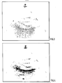
- the image, appearing both on the display tube 24 and on a record made from the recording CRT 26, will be in the form of a succession of laterally disconnected dots arranged as an array of radial lines, as shown in Figure 3.
- the fill circuit or interpolation circuit 18 when the fill circuit or interpolation circuit 18 is in use, the image on the face of the display CRT 24 and on the record formed from the recording CRT 26 will appear with the laterally disconnected dots now connected by interpolated shades of gray to produce a smoother image as shown in Figure 4.
- the image in Figure 3 appears as a number of radial lines each spaced from the next adjacent line, with the data appearing as variable density marks representing the individual data units. In Figure 4, however, there has been an interpolation of data between the distinct radial lines to fill in appropriate data to provide the smoother image pattern.
- the A to D converter 8 converts the analog information into a four bit data words representing 16 shades of gray, or digital values from 0 to 15.
- the coder 12 in Figure 1, forces all of the 0's in the significant data stream to become 1's. This conversion, of course, applies only to the data received from the transducer and transmitted through the A to D converter to the coder 12.- This arrangement provides for a positive distinction between image data and true zero or background data.
- the data stored in the image memory 14 in the pattern of the fan shaped sector will have values ranging between 1 to 15 whereas the data surrounding the fan shaped image will be all 0's.
- the memory data cells or pixels between the radial lines of data in the image memory will also be 0's or data spaces.
- the data stored in the image memory is read out in a line by line or raster scan and applied to the input of the fill circuit 18, as shown in Figure 1.
- the fill circuit 18 is shown in detail in Figure 2.
- the image memory 14 is scanned on a line by line basis. Before each cycle of data is loaded into the image memory, that memory is controlled to clear all addresses or pixels to 0.
- the data received from the A to D converter 8 through the buffer 10 and the coder 12 is loaded into the asisgned addresses in the image memory 14 under the control of the array processor 16.
- the data received from the transducer and converted by the A to D converter is limited by the coder 12 to a minimum value of 1 on a scale of 0 to 15 corresponding to the relative intensity of the signal received by the transducer.
- the signals received by the transducer are serial strings of data arranged in a succession of spaced radial lines.
- the array processor 16 is arranged to store the received data in the image memory 14 in the pattern corresponding to those spaced radial lines.
- the minimum value for the signals in any of the spaced radial lines will be a value of 1 on a scale of 0 to 15.
- the pixels or data units in the memory between the spaced radial lines will contain.0's, as will the data lying beyond the two edges of the fan shaped data area.
- FIFO memory unit 30 When that data is read out of the image memory 14 in a line-by-line scanning order; the number of 0 valued pixels between successive non-zero valued pixels is detected and counted by a zero data counter 32 and stored in the lower or zero count portion of a FIFO memory 30. The value of the data, on the scale of 0 to 15, read from the image memory is stored directly into the upper or gray data portion of the FIFO memory unit 30.
- the FIFO memory unit 30 is an asynchronous memory unit.
- the zero count data is read from the FIFO unit,30 into a preset counter 40 while the gray data is read simultaneously into an old value register 34 and a summer 36. From the edge of the display to the beginning of the fan shaped array, the gray data will be all 0's. It has been found that in the,radial line array of data, there will never be as many as eight successive 0's between any two non-zero pixels in the data display. Therefore any succession of 8 or more 0's is indicative of the presence of a true 0 value.
- the 8 or more 0's are recognized by the preset counter 40 and decoded by a decoder 22 to set a multiplexor 46 to read the old value, i.e:, 0 from the register 34, bypassing the interpolation.
- a decoder 22 Whenthe far edge of the fan shaped display has been reached, there will again be a number of 0's in excess of 8 detected. Again the multiplexer will be actuated to read the last active data from the old value register 34 without interpolation to the 0 level. This will, of course, be followed by all 0's from the register 34.
- the successive data values on each scan line are subtracted in a summer 36 to provide a value equal to the difference in intensity between the two successive data points on the scan lines.
- the distance between those two data points is measured by the number of consecutive 0's counted by the zero data counter and transmitted through the FIFO 30.
- the objective of the interpolation system is to determine the magnitude of the difference between adjacent significant data bits, to divide that value by the distance between successive sig- ' nificant data cells or pixels to produce a fractional value, and to sum that fractional value with the last preceding value, so as to produce a graduated transition between actual measured values over the space between measured values.
- the first significant value is transferred from the output of the old value register 34 into the multiplexor 46 and . thence to a register 48.
- the difference between that old value and the next significant non-zero value is determined by the summer 36.
- the distance between successivelnon- zero values is determined by the zero data counter 32 and transmitted through the FIFO 30 to a ROM 38, which is also fed by the summer 36.
- the data stored in the ROM 38 is a table of fractional values representing possible gray scale values on a scale of 1 to 15 divided by zero count numbers of 1 to 8.
- the 1 to 8 divisors represents the actual count of zero plus 1, since the number of samples of fill the spaces between adjacent non-zero values is 1 less than the actual count number.
- the difference signal from the summer 36 and the zero count number from the zero count portion of the FIFO memory unit 30 applied to the input of the ROM 38 together select a value, at an address determined by the two input signals, which is the value representative of the difference signal divided by the count number plus 1. That fractional value output from the ROM 38 is summed in a summer 44 with the previous value taken from the output of the register 48. The output of the summer 44 is then applied through the multiplexer 46 to the input of the register 48 where the value stored is now the previous value plus the fractional increment. That value is then applied through a multiplexer 52 to the digital-to-analog converter 20, and thence to the display and recording apparatus.
- the new value in the register 48 is now returned to the summer 44 where it is again summed with the increment and again returned to the register and applied through the multiplexor 52 to the digital-to-analog converter 20. This process is continued until the desired number of increments have been added and a new non-zero value is received from the gray data portion of the FIFO memory 30. In this manner, the values corresponding to differing shades of gray between adjacent non-zero values of the gray data received into the FIFO 30 are properly interpolated to provide a fill for the spaces between the radial lines of the image scan. These values are then clocked out of the register 48 by the dot clock 50 at a rate corresponding to the frequency of the individual dot elements on the CRT devices.
- the old value register is updated to store the last previous value and is then compared with the new value of the non-zero gray data.
- the interpolation process is then repeated for these two values and each successive pair of values across each line scan of the image memory. In this manner, the displayed or recorded image resulting from the interpolation presents a more readable and more esthetically pleasant image than the disconnected samples shown in Figure 3.
- a select signal is-applied to the multiplexer 52 to transmit the data directly from the image memory to the digital-to-analog converter 20 and thence onto the image 2 to produce an image such as that shown in Figure 3.
Landscapes
- Engineering & Computer Science (AREA)
- Physics & Mathematics (AREA)
- General Physics & Mathematics (AREA)
- Computational Mathematics (AREA)
- Mathematical Analysis (AREA)
- Mathematical Optimization (AREA)
- Pure & Applied Mathematics (AREA)
- Theoretical Computer Science (AREA)
- Data Mining & Analysis (AREA)
- Mathematical Physics (AREA)
- Databases & Information Systems (AREA)
- Software Systems (AREA)
- General Engineering & Computer Science (AREA)
- Algebra (AREA)
- Computer Networks & Wireless Communication (AREA)
- Radar, Positioning & Navigation (AREA)
- Remote Sensing (AREA)
- Ultra Sonic Daignosis Equipment (AREA)
- Image Processing (AREA)
- Image Analysis (AREA)
Applications Claiming Priority (2)
| Application Number | Priority Date | Filing Date | Title |
|---|---|---|---|
| US17387480A | 1980-07-30 | 1980-07-30 | |
| US173874 | 1980-07-30 |
Publications (3)
| Publication Number | Publication Date |
|---|---|
| EP0045224A2 true EP0045224A2 (fr) | 1982-02-03 |
| EP0045224A3 EP0045224A3 (en) | 1982-10-06 |
| EP0045224B1 EP0045224B1 (fr) | 1986-02-26 |
Family
ID=22633876
Family Applications (1)
| Application Number | Title | Priority Date | Filing Date |
|---|---|---|---|
| EP81303500A Expired EP0045224B1 (fr) | 1980-07-30 | 1981-07-30 | Moyens d'interpolation pour l'affichage d'images |
Country Status (4)
| Country | Link |
|---|---|
| EP (1) | EP0045224B1 (fr) |
| JP (1) | JPS5756892A (fr) |
| CA (1) | CA1159957A (fr) |
| DE (1) | DE3173875D1 (fr) |
Cited By (3)
| Publication number | Priority date | Publication date | Assignee | Title |
|---|---|---|---|---|
| EP0071923A3 (en) * | 1981-08-07 | 1985-07-24 | General Electric Company | Method and means for generating pixel data in an ultrasonic scanning system |
| EP0071924A3 (fr) * | 1981-08-07 | 1985-07-31 | General Electric Company | Procédé et appareil pour l'amélioration de l'image d'un affichage vidéo |
| EP0265334A3 (en) * | 1986-10-20 | 1989-10-25 | Elscint Ltd. | Binary space interpolation |
Families Citing this family (2)
| Publication number | Priority date | Publication date | Assignee | Title |
|---|---|---|---|---|
| JPS58173421A (ja) * | 1982-04-06 | 1983-10-12 | Mitsutoyo Mfg Co Ltd | 自動内側測定機 |
| JP3406106B2 (ja) * | 1995-02-06 | 2003-05-12 | ジーイー横河メディカルシステム株式会社 | 超音波画像表示方法および超音波診断装置 |
Family Cites Families (4)
| Publication number | Priority date | Publication date | Assignee | Title |
|---|---|---|---|---|
| GB1471531A (en) * | 1973-04-25 | 1977-04-27 | Emi Ltd | Radiography |
| GB1515307A (en) * | 1974-07-20 | 1978-06-21 | Emi Ltd | Image reconstruction |
| DE2556012A1 (de) * | 1975-12-12 | 1977-06-16 | Philips Patentverwaltung | Verfahren und anordnung zur ermittlung der raeumlichen verteilung einer strahlung in einer ebene eines koerpers |
| JPS5481095A (en) * | 1977-12-12 | 1979-06-28 | Toshiba Corp | Computer tomography device |
-
1981
- 1981-07-03 CA CA000381113A patent/CA1159957A/fr not_active Expired
- 1981-07-30 DE DE8181303500T patent/DE3173875D1/de not_active Expired
- 1981-07-30 EP EP81303500A patent/EP0045224B1/fr not_active Expired
- 1981-07-30 JP JP56120604A patent/JPS5756892A/ja active Pending
Cited By (3)
| Publication number | Priority date | Publication date | Assignee | Title |
|---|---|---|---|---|
| EP0071923A3 (en) * | 1981-08-07 | 1985-07-24 | General Electric Company | Method and means for generating pixel data in an ultrasonic scanning system |
| EP0071924A3 (fr) * | 1981-08-07 | 1985-07-31 | General Electric Company | Procédé et appareil pour l'amélioration de l'image d'un affichage vidéo |
| EP0265334A3 (en) * | 1986-10-20 | 1989-10-25 | Elscint Ltd. | Binary space interpolation |
Also Published As
| Publication number | Publication date |
|---|---|
| DE3173875D1 (en) | 1986-04-03 |
| EP0045224B1 (fr) | 1986-02-26 |
| CA1159957A (fr) | 1984-01-03 |
| JPS5756892A (en) | 1982-04-05 |
| EP0045224A3 (en) | 1982-10-06 |
Similar Documents
| Publication | Publication Date | Title |
|---|---|---|
| US4428059A (en) | Real time fill circuit | |
| US4241608A (en) | Ultrasonic scanner | |
| EP0035213B1 (fr) | Appareil de diagnostic à ultrasons | |
| US4070905A (en) | Ultrasonic beam scanning | |
| EP0032513B1 (fr) | Materiel de diagnostic a ultrasons | |
| US4922917A (en) | Ultrasonic tissue characterization | |
| US4216465A (en) | Programmable analog to digital converter | |
| EP0143664B1 (fr) | Caractérisation ultrasonique d'un milieu | |
| US4011750A (en) | Method and apparatus for ultrasonic examination of objects | |
| GB1587893A (en) | Ultrasound transmitting or receiving apparatus | |
| US4785402A (en) | Ultrasonic imaging apparatus for color display of flow velocity | |
| GB2151787A (en) | Method and apparatus for displaying a plurality of detected signals per pixel | |
| US4434661A (en) | Ultrasonic diagnostic system | |
| US3909771A (en) | Ophthalmic B-scan apparatus | |
| US4370646A (en) | Method and means for controlling electron beam in a raster scan monitor | |
| JPS6040983A (ja) | 超音波走査装置において実時間で像のズ−ム表示を行うための方法および装置 | |
| US4773425A (en) | Ultrasonic imaging apparatus | |
| EP0045224B1 (fr) | Moyens d'interpolation pour l'affichage d'images | |
| US4099419A (en) | Ultrasonic tomography apparatus | |
| US4949313A (en) | Ultrasonic diagnostic apparatus and pulse compression apparatus for use therein | |
| EP0001933A2 (fr) | Système d'affichage vidéo de balayage type-A pour équipement diagnostique à ultrasons | |
| EP0002061A1 (fr) | Convertisseur de balayage pour dispositif de balayage de secteur à ultrasons et procédé | |
| EP0136857B1 (fr) | Appareil pour observer le champ sonore d'une onde ultrasonique | |
| US4230124A (en) | Output display for B-scan ultrasonoscope | |
| US4837749A (en) | Ultrasonic imaging system for obtaining zoom video images of an object |
Legal Events
| Date | Code | Title | Description |
|---|---|---|---|
| PUAI | Public reference made under article 153(3) epc to a published international application that has entered the european phase |
Free format text: ORIGINAL CODE: 0009012 |
|
| AK | Designated contracting states |
Designated state(s): DE FR GB |
|
| PUAL | Search report despatched |
Free format text: ORIGINAL CODE: 0009013 |
|
| 17P | Request for examination filed |
Effective date: 19820726 |
|
| AK | Designated contracting states |
Designated state(s): DE FR GB |
|
| RAP1 | Party data changed (applicant data changed or rights of an application transferred) |
Owner name: BIOSOUND, INC. |
|
| GRAA | (expected) grant |
Free format text: ORIGINAL CODE: 0009210 |
|
| AK | Designated contracting states |
Designated state(s): DE FR GB |
|
| REF | Corresponds to: |
Ref document number: 3173875 Country of ref document: DE Date of ref document: 19860403 |
|
| ET | Fr: translation filed | ||
| PLBE | No opposition filed within time limit |
Free format text: ORIGINAL CODE: 0009261 |
|
| STAA | Information on the status of an ep patent application or granted ep patent |
Free format text: STATUS: NO OPPOSITION FILED WITHIN TIME LIMIT |
|
| 26N | No opposition filed | ||
| PG25 | Lapsed in a contracting state [announced via postgrant information from national office to epo] |
Ref country code: GB Effective date: 19880730 |
|
| GBPC | Gb: european patent ceased through non-payment of renewal fee | ||
| PG25 | Lapsed in a contracting state [announced via postgrant information from national office to epo] |
Ref country code: FR Free format text: LAPSE BECAUSE OF NON-PAYMENT OF DUE FEES Effective date: 19890331 |
|
| PG25 | Lapsed in a contracting state [announced via postgrant information from national office to epo] |
Ref country code: DE Effective date: 19890401 |
|
| REG | Reference to a national code |
Ref country code: FR Ref legal event code: ST |