EP0045256A2 - Verfahren und Vorrichtung zum Vergasen von Pflanzenmaterialien - Google Patents
Verfahren und Vorrichtung zum Vergasen von Pflanzenmaterialien Download PDFInfo
- Publication number
- EP0045256A2 EP0045256A2 EP81401189A EP81401189A EP0045256A2 EP 0045256 A2 EP0045256 A2 EP 0045256A2 EP 81401189 A EP81401189 A EP 81401189A EP 81401189 A EP81401189 A EP 81401189A EP 0045256 A2 EP0045256 A2 EP 0045256A2
- Authority
- EP
- European Patent Office
- Prior art keywords
- materials
- chamber
- treatment chamber
- gases
- treated
- Prior art date
- Legal status (The legal status is an assumption and is not a legal conclusion. Google has not performed a legal analysis and makes no representation as to the accuracy of the status listed.)
- Withdrawn
Links
Images

Classifications
-
- C—CHEMISTRY; METALLURGY
- C10—PETROLEUM, GAS OR COKE INDUSTRIES; TECHNICAL GASES CONTAINING CARBON MONOXIDE; FUELS; LUBRICANTS; PEAT
- C10J—PRODUCTION OF PRODUCER GAS, WATER-GAS, SYNTHESIS GAS FROM SOLID CARBONACEOUS MATERIAL, OR MIXTURES CONTAINING THESE GASES; CARBURETTING AIR OR OTHER GASES
- C10J3/00—Production of combustible gases containing carbon monoxide from solid carbonaceous fuels
- C10J3/002—Horizontal gasifiers, e.g. belt-type gasifiers
-
- C—CHEMISTRY; METALLURGY
- C10—PETROLEUM, GAS OR COKE INDUSTRIES; TECHNICAL GASES CONTAINING CARBON MONOXIDE; FUELS; LUBRICANTS; PEAT
- C10J—PRODUCTION OF PRODUCER GAS, WATER-GAS, SYNTHESIS GAS FROM SOLID CARBONACEOUS MATERIAL, OR MIXTURES CONTAINING THESE GASES; CARBURETTING AIR OR OTHER GASES
- C10J3/00—Production of combustible gases containing carbon monoxide from solid carbonaceous fuels
- C10J3/02—Fixed-bed gasification of lump fuel
- C10J3/20—Apparatus; Plants
-
- C—CHEMISTRY; METALLURGY
- C10—PETROLEUM, GAS OR COKE INDUSTRIES; TECHNICAL GASES CONTAINING CARBON MONOXIDE; FUELS; LUBRICANTS; PEAT
- C10J—PRODUCTION OF PRODUCER GAS, WATER-GAS, SYNTHESIS GAS FROM SOLID CARBONACEOUS MATERIAL, OR MIXTURES CONTAINING THESE GASES; CARBURETTING AIR OR OTHER GASES
- C10J3/00—Production of combustible gases containing carbon monoxide from solid carbonaceous fuels
- C10J3/02—Fixed-bed gasification of lump fuel
- C10J3/20—Apparatus; Plants
- C10J3/22—Arrangements or dispositions of valves or flues
- C10J3/24—Arrangements or dispositions of valves or flues to permit flow of gases or vapours other than upwardly through the fuel bed
-
- C—CHEMISTRY; METALLURGY
- C10—PETROLEUM, GAS OR COKE INDUSTRIES; TECHNICAL GASES CONTAINING CARBON MONOXIDE; FUELS; LUBRICANTS; PEAT
- C10J—PRODUCTION OF PRODUCER GAS, WATER-GAS, SYNTHESIS GAS FROM SOLID CARBONACEOUS MATERIAL, OR MIXTURES CONTAINING THESE GASES; CARBURETTING AIR OR OTHER GASES
- C10J3/00—Production of combustible gases containing carbon monoxide from solid carbonaceous fuels
- C10J3/02—Fixed-bed gasification of lump fuel
- C10J3/20—Apparatus; Plants
- C10J3/30—Fuel charging devices
-
- C—CHEMISTRY; METALLURGY
- C10—PETROLEUM, GAS OR COKE INDUSTRIES; TECHNICAL GASES CONTAINING CARBON MONOXIDE; FUELS; LUBRICANTS; PEAT
- C10J—PRODUCTION OF PRODUCER GAS, WATER-GAS, SYNTHESIS GAS FROM SOLID CARBONACEOUS MATERIAL, OR MIXTURES CONTAINING THESE GASES; CARBURETTING AIR OR OTHER GASES
- C10J3/00—Production of combustible gases containing carbon monoxide from solid carbonaceous fuels
- C10J3/02—Fixed-bed gasification of lump fuel
- C10J3/20—Apparatus; Plants
- C10J3/34—Grates; Mechanical ash-removing devices
- C10J3/36—Fixed grates
-
- C—CHEMISTRY; METALLURGY
- C10—PETROLEUM, GAS OR COKE INDUSTRIES; TECHNICAL GASES CONTAINING CARBON MONOXIDE; FUELS; LUBRICANTS; PEAT
- C10J—PRODUCTION OF PRODUCER GAS, WATER-GAS, SYNTHESIS GAS FROM SOLID CARBONACEOUS MATERIAL, OR MIXTURES CONTAINING THESE GASES; CARBURETTING AIR OR OTHER GASES
- C10J3/00—Production of combustible gases containing carbon monoxide from solid carbonaceous fuels
- C10J3/46—Gasification of granular or pulverulent flues in suspension
- C10J3/48—Apparatus; Plants
- C10J3/50—Fuel charging devices
- C10J3/503—Fuel charging devices for gasifiers with stationary fluidised bed
-
- C—CHEMISTRY; METALLURGY
- C10—PETROLEUM, GAS OR COKE INDUSTRIES; TECHNICAL GASES CONTAINING CARBON MONOXIDE; FUELS; LUBRICANTS; PEAT
- C10J—PRODUCTION OF PRODUCER GAS, WATER-GAS, SYNTHESIS GAS FROM SOLID CARBONACEOUS MATERIAL, OR MIXTURES CONTAINING THESE GASES; CARBURETTING AIR OR OTHER GASES
- C10J3/00—Production of combustible gases containing carbon monoxide from solid carbonaceous fuels
- C10J3/58—Production of combustible gases containing carbon monoxide from solid carbonaceous fuels combined with pre-distillation of the fuel
- C10J3/60—Processes
- C10J3/64—Processes with decomposition of the distillation products
- C10J3/66—Processes with decomposition of the distillation products by introducing them into the gasification zone
-
- C—CHEMISTRY; METALLURGY
- C10—PETROLEUM, GAS OR COKE INDUSTRIES; TECHNICAL GASES CONTAINING CARBON MONOXIDE; FUELS; LUBRICANTS; PEAT
- C10J—PRODUCTION OF PRODUCER GAS, WATER-GAS, SYNTHESIS GAS FROM SOLID CARBONACEOUS MATERIAL, OR MIXTURES CONTAINING THESE GASES; CARBURETTING AIR OR OTHER GASES
- C10J2300/00—Details of gasification processes
- C10J2300/09—Details of the feed, e.g. feeding of spent catalyst, inert gas or halogens
- C10J2300/0913—Carbonaceous raw material
- C10J2300/0916—Biomass
-
- C—CHEMISTRY; METALLURGY
- C10—PETROLEUM, GAS OR COKE INDUSTRIES; TECHNICAL GASES CONTAINING CARBON MONOXIDE; FUELS; LUBRICANTS; PEAT
- C10J—PRODUCTION OF PRODUCER GAS, WATER-GAS, SYNTHESIS GAS FROM SOLID CARBONACEOUS MATERIAL, OR MIXTURES CONTAINING THESE GASES; CARBURETTING AIR OR OTHER GASES
- C10J2300/00—Details of gasification processes
- C10J2300/09—Details of the feed, e.g. feeding of spent catalyst, inert gas or halogens
- C10J2300/0953—Gasifying agents
- C10J2300/0956—Air or oxygen enriched air
-
- C—CHEMISTRY; METALLURGY
- C10—PETROLEUM, GAS OR COKE INDUSTRIES; TECHNICAL GASES CONTAINING CARBON MONOXIDE; FUELS; LUBRICANTS; PEAT
- C10J—PRODUCTION OF PRODUCER GAS, WATER-GAS, SYNTHESIS GAS FROM SOLID CARBONACEOUS MATERIAL, OR MIXTURES CONTAINING THESE GASES; CARBURETTING AIR OR OTHER GASES
- C10J2300/00—Details of gasification processes
- C10J2300/09—Details of the feed, e.g. feeding of spent catalyst, inert gas or halogens
- C10J2300/0953—Gasifying agents
- C10J2300/0959—Oxygen
-
- C—CHEMISTRY; METALLURGY
- C10—PETROLEUM, GAS OR COKE INDUSTRIES; TECHNICAL GASES CONTAINING CARBON MONOXIDE; FUELS; LUBRICANTS; PEAT
- C10J—PRODUCTION OF PRODUCER GAS, WATER-GAS, SYNTHESIS GAS FROM SOLID CARBONACEOUS MATERIAL, OR MIXTURES CONTAINING THESE GASES; CARBURETTING AIR OR OTHER GASES
- C10J2300/00—Details of gasification processes
- C10J2300/18—Details of the gasification process, e.g. loops, autothermal operation
- C10J2300/1807—Recycle loops, e.g. gas, solids, heating medium, water
- C10J2300/1823—Recycle loops, e.g. gas, solids, heating medium, water for synthesis gas
Definitions
- the subject of the present invention is in particular a process for gasifying materials of plant origin in a treatment chamber, a process of the type according to which gases which have passed through materials are being extracted, these gases are recycled and they are reheated to produce hot gases which are injected into the treatment chamber.
- the object of the present invention is to further improve the treatment of materials by making them pass optimally through the heated gas flow resulting from recycling, this without necessarily imposing a particular orientation of the treatment chamber.
- These materials form a thin layer, that is to say a layer of thickness less than about 10 to 30 times the average size of the particles of material to be treated. This avoids unnecessary pressure drops which would be produced by passing through an additional layer of material within which the chemical reactions would be slow.
- Heating of the recycled gases can be carried out by combustion of a part of these combined with combustion air or oxygen or by passage through an electric arc, or by any other suitable means.
- gases from different zones located along the treatment chamber are extracted separately. It is then possible to adjust the flow of extracted gases in the different zones separately.
- the action of the hot gases can thus be optimized as a function of the flow characteristics of the gases through the layer of material crossed, that is to say in particular as a function of the thickness of this layer and / or of the grain size. subjects.
- the materials being processed are advanced in the horizontal direction or slightly inclined relative to the horizontal and the material bed is passed through from its upper surface to its lower surface by hot gas flow.
- the object of the present invention is also to provide an installation making it possible to implement the method according to the invention.
- an installation comprising a treatment chamber in which the materials being treated progress longitudinally, an outlet for sampling the gases produced by the installation, extraction means through a wall of the gas chamber having passed through materials being treated, a device for recycling the extracted gases, and means for heating the recycled gases and injecting them into the treatment chamber, installation in which, in accordance with the invention, the treatment chamber present at the at least one longitudinal gas permeable wall which separates the treatment chamber from at least one extraction chamber, and the injection means and the extraction chamber or chambers are located along two opposite longitudinal faces of the treatment in order to make practically all of the materials being treated pass through a gas flow of direction substantially transverse to the direction of progression of the materials to be treated in the treatment chamber.
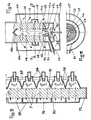
- Figures 1 and 2 illustrate an installation according to the invention with a treatment chamber 10 of rectangular cross section in which the materials to be treated are introduced at the rear end 10a.
- the chamber 10 extends longitudinally in the horizontal direction or slightly inclined relative to the horizontal downwards and forwards 10b.
- the possible inclination of the chamber serves to facilitate the progression of the materials forward, without this progression being possible by the sole effect of gravity.
- the materials to be treated progress in the chamber 10 under the effect of a pusher 11 which is driven back and forth with slow advance and rapid recoil.
- the loading of the materials to be treated is carried out through a loading opening behind the processing chamber.
- Other methods could be used to ensure the progression of the materials in the chamber 10, for example a movable grid, scraper bars, vibrating grids, or even fluidization.
- the bottom wall 12 of the chamber 10 is permeable to gases from the rear end 10a of the chamber and practically over the entire length of the latter.
- This wall is for example constituted by a grid 19 which separates the interior of the chamber 10 from several extraction chambers 13.
- the chambers 13 are arranged side by side substantially along the entire length of the chamber 10 and are separated from each other. other.
- each grid 19 are arranged in longitudinal planes being slightly inclined upwards towards the front of the chamber 10. More precisely, the rear end of each bar is located slightly below the top of the rear wall of the corresponding chamber 13 while the front end of each bar is situated slightly above the front wall of this chamber. Thus, the materials being processed do not encounter obstacles liable to hinder their progress.
- a recycling duct 14 provided with a suction fan 15 is connected to each chamber 13. At its other end, each recycling duct 14 leads to a particular injector 16 also receiving combustion air or oxygen through a line 17 supplying all the injectors.
- Each injector 16 opens in a dilution chamber 18 which communicates with the treatment chamber through an opening 18a in the upper wall thereof. It will be noted that the chamber 10 is open practically over its entire upper face, the chambers 18 being arranged side by side along the chamber 10.
- One of the chambers 13 constitutes the outlet of the gasometer and is provided with an outlet for the gases produced by the installation.
- This outlet chamber may possibly not be associated with a recycling conduit.
- the chambers 13 are provided, as necessary, with devices for extracting the ashes having passed through the grids 19.
- each extraction chamber 13 is connected by its particular recycling conduit 14 to a particular injector 16 which occupies, in the row of injectors, the same rank as that occupied by the chamber 13 in the row of chambers extraction.
- connection possibilities can be chosen between chambers 13 and injectors 16. It is even conceivable to mix the gases extracted from the different chambers 13 to supply injectors distributed along the chamber 10.
- the operation of the installation is as follows.
- the materials to be gasified are introduced into the chamber. These are materials of plant origin, such as charcoal, wood, coconut shells or other vegetable waste possibly agglomerated.
- the materials successively undergo drying, pyrolysis and gasification.
- the gases produced by the installation are collected at the outlet of the chamber 13 provided for this purpose. This is placed downstream of the pyrolysis zone in the direction of progression of the materials to be treated, which makes it possible to collect gases free from the pyrolysis tars and in an area where the carbon layer is homogeneous and sufficient, if the '' we seek to obtain gases with a high lower calorific value.
- the tars are transported by the recycled gases having passed through the pyrolysis zone and are then removed by cracking or combustion at the outlet of the injectors 16.
- the thermal reaction is initialized by means of burners (not shown) producing the necessary hot gases.
- burners (not shown) producing the necessary hot gases.
- the burners are shut down and the hot gases are produced by means of the gases which are drawn into the extraction chambers then which are recycled and combined with combustion air or oxygen in the injectors 16.
- the hot gases are produced in the chambers 18 and attack the upper face of the bed of materials contained in the chamber 10. It will be noted that the chambers 18 as well as the free space between the upper surface of the bed of materials and the upper limit of the room allow dilution of the combustion gases before their penetration into the materials to be treated.
- the hot gas flow (arrows F) generated by the recycling and the exit of the gases passes simultaneously through the entire bed of materials being treated, perpendicular to the direction of advance A of the materials being processed treatment.
- the short path of the gas flow allows it to reach with a high temperature all the materials forming the bed throughout its thickness. In this regard, it is desirable that this thickness does not exceed about 10 times for wood and 20 to 30 times for coal the average size of the particles of material to be treated.
- An efficient and rapid treatment is obtained by recycling at a high temperature, that is to say by recycling gases whose temperature is preferably above 500 ° C.
- the invention can also be applied to installations of the fluidized bed type. For this, it suffices, in the installation illustrated in FIGS. 1 and 2, to reverse the positions of the extraction chambers 13, on the one hand, and of the injectors 16 with the dilution chambers 18, on the other hand go.
- the hot gas flow then crosses the bed of materials from bottom to top. It then performs the treatment of the materials and the fluidization of the bed of these materials.
- FIGS. 3 to 5 illustrate two other embodiments of the invention using vertical type treatment chambers in which the materials to be treated progress by gravity only.
- extraction chambers 33 which are separated from the vertical treatment chamber 30 by a permeable partition 32 gas.
- One of the chambers 33 is used as an outlet for the gases produced by the installation.
- the chamber 30 has a rectangular cross section and its lower end wall is constituted by a grid 39 through which fall the gasification residues.
- the chambers 33 are located along one of the two longitudinal walls of the chamber.
- dilution chambers 38 are arranged which communicate with the interior of the chamber 30 through a gas-permeable wall 31, for example a grid or a perforated sheet, like the wall 32.
- Injectors 36 open into the chambers 38. These injectors are connected to the ex chambers traction 33 by recycling conduits (not shown) fitted with ventilator-aspirators establishing forced circulation in these conduits from the chambers 33 to the injectors 36. The gases thus extracted and recycled are partly combined with air or l combustion oxygen supplied via a line 37 to the various injectors 36.
- the vertical treatment chamber 40 has a cross section of annular shape delimited laterally by two concentric external 41 and internal 42 walls and lower by a horizontal grid 49.
- the inner wall 42 is gas permeable over the entire height of the chamber 40 and delimits a central chamber 48 closed at its upper end by a wall 48a and open at its lower end.
- the outer wall 41 is permeable to gases from the upper end of the chamber 40 and over practically the entire height of the latter.
- This wall 41 separates the interior of the chamber 40 from an extraction chamber 43 which is closed at its upper part by a horizontal annular wall 43a and which extends from the top of the chamber 40 to a lower wall horizontal 43b located below and at a distance from the bottom of the chamber 40.
- the outer wall 41 is extended downwards by a solid cylindrical wall to a horizontal end wall 41a provided with an axial opening 41b.
- the nozzle 47a opens axially upwards and is connected by a conduit 47, which passes through the chamber 43 in a sealed manner, to an external supply of air or combustion oxygen.
- the ash box 50 is connected to an inclined evacuation passage 51 which passes through the chamber 43 in a leaktight manner and opens to the outside.
- the gases extracted in the chamber 43 are sucked by the fan 45 in the recycling duct 44 formed between the walls 43b and 41b and are introduced into the central chamber 48 through the annular space surrounding the nozzle 47a and closing the injector 46 .
- the gases heated at the outlet of the injector 46 are distributed in the chamber 48.
- the suction in the chamber 43 produces a transverse hot gas flow (arrows F) through the entire bed of materials located in the chamber 40. These materials are introduced at the top of the chamber 40 delimited by a solid upper extension of the wall 41, above the upper wall 48a closing the dilution chamber 48.
- the gases produced by the installation are sampled in an annular outlet chamber 43 ′ which is adjacent to the wall 41 and which is located inside the extraction chamber 43 while being isolated from it. .
- the chamber 43 ' is located at a level below that of the pyrolysis zone in the chamber 40.
- a pipe (not shown) communicates the chamber 43' with the outside of the extraction chamber.
- a single fan 45 is provided and is arranged below the dilution chamber 48.
- several fans may be arranged at different levels from the dilution chamber, in particular in depending on the height of the installation.
- the gas flow passing through the column of materials is oriented either transversely in one direction (FIG. 3), or radially only from the inside to the outside. It is however possible, in the context of the invention, to pass the column of materials through a gas flow whose direction is always transverse but whose direction may differ in different sections of the column of materials. This can be obtained, in the case for example of FIG. 3, by placing the extraction chambers, as well as the dilution chambers, on each of the opposite sides 31, 32 of the chamber 30 and not on the same side. .
Landscapes
- Chemical & Material Sciences (AREA)
- Engineering & Computer Science (AREA)
- Combustion & Propulsion (AREA)
- Oil, Petroleum & Natural Gas (AREA)
- Organic Chemistry (AREA)
- Mechanical Engineering (AREA)
- Seasonings (AREA)
- Devices And Processes Conducted In The Presence Of Fluids And Solid Particles (AREA)
- Processing Of Solid Wastes (AREA)
Applications Claiming Priority (2)
| Application Number | Priority Date | Filing Date | Title |
|---|---|---|---|
| FR8016854A FR2487847A1 (fr) | 1980-07-30 | 1980-07-30 | Procede et installation de gazeification de matieres d'origine vegetale |
| FR8016854 | 1980-07-30 |
Publications (2)
| Publication Number | Publication Date |
|---|---|
| EP0045256A2 true EP0045256A2 (de) | 1982-02-03 |
| EP0045256A3 EP0045256A3 (de) | 1982-02-10 |
Family
ID=9244725
Family Applications (1)
| Application Number | Title | Priority Date | Filing Date |
|---|---|---|---|
| EP81401189A Withdrawn EP0045256A3 (de) | 1980-07-30 | 1981-07-24 | Verfahren und Vorrichtung zum Vergasen von Pflanzenmaterialien |
Country Status (4)
| Country | Link |
|---|---|
| EP (1) | EP0045256A3 (de) |
| BR (1) | BR8104888A (de) |
| FR (1) | FR2487847A1 (de) |
| OA (1) | OA06875A (de) |
Cited By (10)
| Publication number | Priority date | Publication date | Assignee | Title |
|---|---|---|---|---|
| EP0094893A1 (de) * | 1982-05-19 | 1983-11-23 | Creusot-Loire | Verfahren und Vorrichtung zur Behandlung eines festen kleinstückigen Materials |
| FR2553097A1 (fr) * | 1983-10-07 | 1985-04-12 | Creusot Loire | Installation de traitement d'une matiere combustible et son mode de fonctionnement |
| ES2086262A1 (es) * | 1994-07-07 | 1996-06-16 | Areizaga Iglesias Adolfo De | Proceso de gasificacion de residuos de biomasa. |
| DE19519812C1 (de) * | 1995-05-31 | 1996-07-11 | Esselte Meto Int Gmbh | Drucker |
| WO2001096500A1 (de) | 2000-06-13 | 2001-12-20 | Christian Herlt | Verfahren und vorrichtung zum vergasen grossstückiger festbrennstoffe, insbesondere biomasse |
| FR2916760A1 (fr) * | 2007-06-01 | 2008-12-05 | Isaac Behar | Module, systeme et procede de traitement de biomasse a lit fixe horizontal |
| WO2009009891A1 (en) * | 2007-07-17 | 2009-01-22 | Plasco Energy Group Inc. | A gasifier comprising one or more fluid conduits |
| US8128728B2 (en) | 2006-05-05 | 2012-03-06 | Plasco Energy Group, Inc. | Gas homogenization system |
| US8690975B2 (en) | 2007-02-27 | 2014-04-08 | Plasco Energy Group Inc. | Gasification system with processed feedstock/char conversion and gas reformulation |
| US9321640B2 (en) | 2010-10-29 | 2016-04-26 | Plasco Energy Group Inc. | Gasification system with processed feedstock/char conversion and gas reformulation |
Families Citing this family (4)
| Publication number | Priority date | Publication date | Assignee | Title |
|---|---|---|---|---|
| NZ573217A (en) | 2006-05-05 | 2011-11-25 | Plascoenergy Ip Holdings S L Bilbao Schaffhausen Branch | A facility for conversion of carbonaceous feedstock into a reformulated syngas containing CO and H2 |
| MX2008014200A (es) | 2006-05-05 | 2009-06-04 | Plasco Energy Ip Holdings S L | Gasificador orientado horizontalmente con sistema de transferencia lateral. |
| BRPI0711325A2 (pt) | 2006-05-05 | 2011-08-30 | Plascoenergy Ip Holdings S L Bilbao Schaffhausen Branch | sistema de controle para a conversão de um estoque de alimentação carbonáceo em gás |
| FR2914314B1 (fr) * | 2007-03-26 | 2011-04-08 | Litelis | Procede et installation pour la gazeification a puissance variable de matieres combustibles. |
Family Cites Families (8)
| Publication number | Priority date | Publication date | Assignee | Title |
|---|---|---|---|---|
| DE419589C (de) * | 1918-12-31 | 1925-10-06 | Dipl Huettening Wilhelm Corsal | Gaserzeuger mit Ableitung des Fertiggases in mittlerer Hoehe der Brennstoffsaeule |
| GB352271A (en) * | 1929-07-18 | 1931-07-09 | Alfred Jean Andre Hereng | Improvements in or relating to the gasification of solid fuel |
| DE828427C (de) * | 1949-10-29 | 1952-01-17 | Dr Otto Hubmann | Verfahren und Vorrichtung zum Schwelen und Vergasen von Brennstoffen |
| DE954906C (de) * | 1951-07-21 | 1956-12-27 | Walter Puff Dipl Ing | Verfahren zur Vergasung oder zur Ent- und Vergasung aschereicher Brennstoffe |
| DE901329C (de) * | 1951-08-21 | 1954-01-11 | Otto & Co Gmbh Dr C | Verfahren und Schachtofen zur Gewinnung hochwertiger Gase aus aschereichen Brennstoffen |
| DE1055163B (de) * | 1955-06-07 | 1959-04-16 | Otto & Co Gmbh Dr C | Verfahren und Ofen zum Vergasen oder Schwelen von Brennstoffen im Querstrom |
| FR1209694A (fr) * | 1957-09-30 | 1960-03-03 | Ferdinand Lentjes Kesselschmie | Gazogène à gazéification rapide |
| US4030895A (en) * | 1976-03-17 | 1977-06-21 | Caughey Robert A | Apparatus for producing combustible gases from carbonaceous materials |
-
1980
- 1980-07-30 FR FR8016854A patent/FR2487847A1/fr active Granted
-
1981
- 1981-07-24 EP EP81401189A patent/EP0045256A3/de not_active Withdrawn
- 1981-07-29 BR BR8104888A patent/BR8104888A/pt unknown
- 1981-07-29 OA OA57467A patent/OA06875A/xx unknown
Cited By (13)
| Publication number | Priority date | Publication date | Assignee | Title |
|---|---|---|---|---|
| EP0094893A1 (de) * | 1982-05-19 | 1983-11-23 | Creusot-Loire | Verfahren und Vorrichtung zur Behandlung eines festen kleinstückigen Materials |
| FR2553097A1 (fr) * | 1983-10-07 | 1985-04-12 | Creusot Loire | Installation de traitement d'une matiere combustible et son mode de fonctionnement |
| EP0140763A3 (en) * | 1983-10-07 | 1985-06-19 | Creusot-Loire | Installation for the treatmet of fuel material, and its operating mode |
| ES2086262A1 (es) * | 1994-07-07 | 1996-06-16 | Areizaga Iglesias Adolfo De | Proceso de gasificacion de residuos de biomasa. |
| DE19519812C1 (de) * | 1995-05-31 | 1996-07-11 | Esselte Meto Int Gmbh | Drucker |
| US7013816B2 (en) | 2000-06-13 | 2006-03-21 | Christian Herlt | Method for gasifying large pieces of solid fuels, especially bales of biomass |
| WO2001096500A1 (de) | 2000-06-13 | 2001-12-20 | Christian Herlt | Verfahren und vorrichtung zum vergasen grossstückiger festbrennstoffe, insbesondere biomasse |
| US8128728B2 (en) | 2006-05-05 | 2012-03-06 | Plasco Energy Group, Inc. | Gas homogenization system |
| US8690975B2 (en) | 2007-02-27 | 2014-04-08 | Plasco Energy Group Inc. | Gasification system with processed feedstock/char conversion and gas reformulation |
| FR2916760A1 (fr) * | 2007-06-01 | 2008-12-05 | Isaac Behar | Module, systeme et procede de traitement de biomasse a lit fixe horizontal |
| WO2008149026A3 (fr) * | 2007-06-01 | 2009-07-09 | Isaac Behar | Module, systeme et procede de traitement de biomasse a lit fixe horizontal |
| WO2009009891A1 (en) * | 2007-07-17 | 2009-01-22 | Plasco Energy Group Inc. | A gasifier comprising one or more fluid conduits |
| US9321640B2 (en) | 2010-10-29 | 2016-04-26 | Plasco Energy Group Inc. | Gasification system with processed feedstock/char conversion and gas reformulation |
Also Published As
| Publication number | Publication date |
|---|---|
| BR8104888A (pt) | 1982-04-13 |
| FR2487847A1 (fr) | 1982-02-05 |
| EP0045256A3 (de) | 1982-02-10 |
| OA06875A (fr) | 1983-04-30 |
| FR2487847B1 (de) | 1984-11-02 |
Similar Documents
| Publication | Publication Date | Title |
|---|---|---|
| EP0223807B1 (de) | Verfahren zum erzeugen von geröstetem holz, auf diese weise hergestelltes produkt und dessen verwendung zum erzeugen von energie | |
| EP2627739B1 (de) | Vorrichtung zur umwandlung eines brennstoffes | |
| FR2487847A1 (fr) | Procede et installation de gazeification de matieres d'origine vegetale | |
| CH621571A5 (de) | ||
| CA2763409C (fr) | Nouveau procede pour la pyrogazeification de dechets organiques | |
| WO2015082355A1 (fr) | Dispositif de production de charbon vert à usage agricole | |
| FR2931162A1 (fr) | Procede et dispositif de carbonisation | |
| CH459961A (fr) | Appareil pour effectuer des réactions chimiques dans une masse fluide des particules | |
| FR3020451A1 (fr) | Dispositif et systeme pour le sechage de particules heterogenes humides | |
| EP0011037B1 (de) | Vergasungsverfahren und Vergasungsvorrichtung | |
| EP0345336A1 (de) | Verfahren und vorrichtung zur bertinisierung von holzartigen pflanzlichen materialien | |
| EP0010048B1 (de) | Verfahren und Vorrichtung zur zumindest teilweisen Vergasung brennbaren Materials | |
| FR2635274A1 (fr) | Appareil a lit fluidise en circulation | |
| EP0663433A1 (de) | Verfahren zur Behandlung von Abfällen insbesondere Hausmüll und Vorrichtung zur Dürchführung des Verfahrens | |
| EP3960837A1 (de) | Festbett-pyrovergasungsreaktor mit verbessertem leistungsgrad | |
| FR2511028A1 (fr) | Procede et installation pour la gazeification de matieres carbonees | |
| EP0841519A1 (de) | Verfahren und Anlage zur Behandlung durch Verbrennung von Abfällen, und zur Wärmerückgewinnung | |
| FR2505350A1 (fr) | Gazeificateurs de combustibles solides a lit fixe et a tirage inverse | |
| FR2916760A1 (fr) | Module, systeme et procede de traitement de biomasse a lit fixe horizontal | |
| EP4610333A1 (de) | Verkohlungsanlage und verfahren zur herstellung von holzkohle | |
| FR3165276A1 (fr) | Dispositif de pyrolyse pour matériaux biosourcés et procédé de pyrolyse le mettant en œuvre | |
| FR3113312A1 (fr) | Four pour chauffe œnologique de bois | |
| CH230015A (fr) | Appareil pour réaliser la combustion de combustibles solides avec un haut rendement. | |
| FR3047300A1 (fr) | Procede de gazeification et dispositifs permettant de le mettre en oeuvre | |
| CH203908A (fr) | Procédé de distillation, en continu, de matières combustibles carbonées, en particulier de matières cellulosiques, et appareil pour l'exécution de ce procédé. |
Legal Events
| Date | Code | Title | Description |
|---|---|---|---|
| PUAI | Public reference made under article 153(3) epc to a published international application that has entered the european phase |
Free format text: ORIGINAL CODE: 0009012 |
|
| PUAL | Search report despatched |
Free format text: ORIGINAL CODE: 0009013 |
|
| AK | Designated contracting states |
Designated state(s): AT BE CH DE GB IT LU NL SE |
|
| AK | Designated contracting states |
Designated state(s): AT BE CH DE GB IT LU NL SE |
|
| 17P | Request for examination filed |
Effective date: 19820724 |
|
| STAA | Information on the status of an ep patent application or granted ep patent |
Free format text: STATUS: THE APPLICATION IS DEEMED TO BE WITHDRAWN |
|
| 18D | Application deemed to be withdrawn |
Effective date: 19831118 |
|
| RIN1 | Information on inventor provided before grant (corrected) |
Inventor name: GILLE, ETIENNE Inventor name: LUCAS, JEAN Inventor name: MOLLE, JEAN-FRANCOIS Inventor name: CREZE, PATRICK |