EP0045283A2 - Treillis d'armature et son application - Google Patents
Treillis d'armature et son application Download PDFInfo
- Publication number
- EP0045283A2 EP0045283A2 EP81810308A EP81810308A EP0045283A2 EP 0045283 A2 EP0045283 A2 EP 0045283A2 EP 81810308 A EP81810308 A EP 81810308A EP 81810308 A EP81810308 A EP 81810308A EP 0045283 A2 EP0045283 A2 EP 0045283A2
- Authority
- EP
- European Patent Office
- Prior art keywords
- reinforcement
- bars
- distance
- coulter
- mat
- Prior art date
- Legal status (The legal status is an assumption and is not a legal conclusion. Google has not performed a legal analysis and makes no representation as to the accuracy of the status listed.)
- Granted
Links
Images
Classifications
-
- E—FIXED CONSTRUCTIONS
- E04—BUILDING
- E04C—STRUCTURAL ELEMENTS; BUILDING MATERIALS
- E04C5/00—Reinforcing elements, e.g. for concrete; Auxiliary elements therefor
- E04C5/01—Reinforcing elements of metal, e.g. with non-structural coatings
- E04C5/02—Reinforcing elements of metal, e.g. with non-structural coatings of low bending resistance, i.e. of essentially one-dimensional [1D] or two-dimensional [2D] extent
- E04C5/04—Mats
Definitions
- the present invention relates to a reinforcement mat with a rectangular outline, consisting of orthogonally crossing sets of parallel bars connected to one another at the crossing points, of which sets the share with the bars parallel to the shorter side of the rectangle for supporting armoring and the set with the bars parallel to the longer side of the rectangle are dimensioned for a distribution reinforcement, the rods of each share having the same diameter.
- the reinforcement mats that are offered in stock do not correspond to the dimensions required by the customer and must therefore be pushed together.
- the overlap length in the case of overlaps in the longitudinal direction of the mats must correspond to the distance between two bars running perpendicular to the joint. If the cross bars perform the load-bearing function, this dimension is about three times larger.
- DE-AS 1 484 343 it is also proposed to provide such different distances in areas within the mat in order to be able to divide the mats and to have the same steel cross-sections in mats composed in this way as in whole mats. Although this can simplify warehousing, the steel cross-section across the entire mat must be larger than the required minimum dimension so that there are no weakening points in the areas with larger rod spacings.
- this is achieved with a reinforcement mat suitable for supporting reinforcement and edge reinforcement in that in the edge parts of the coulter bars for the supporting reinforcement, the distance between the outermost bar and the adjacent bar is twice as large as the distance between the other bars of this coulter, and that the distance between the two in the middle of the reinforcement mat Members of the coulter bars of the distribution reinforcement is at least twice and at most two and a half times as large as the distances between the other bars of the coulter bars of the distribution reinforcement.
- the increase in distance in the middle of the mat ensures that the U-shaped mats can penetrate other mats for surface reinforcement. If the distance between the two rods located centrally of Verteilarmtechnik by twice the length of the edges of the Tragarmtechnik is increased, the mat can be crossed and the transfer margins obtained are genmers.um g EEO and replace connector iron, can thereby increase the potential applications .
- the larger spacings of the support reinforcement bars provided at the edge of the mat allow covering of adjacent mats with a constant steel cross-section and, as a result, the uniform distribution of the support reinforcement bars, thereby making it easy to monitor the correct arrangement of the mats.
- the object is achieved in that the distance between the outer bar and the bar adjacent to it is twice as large in the edge parts of the coulter bars for the supporting armoring like the distance between the bars, which are otherwise evenly distributed over the width between these edge parts, and that the coulter bars for the supporting reinforcement have two different lengths and are arranged alternately.
- This mat can be used to create intersections with surface structures where connecting iron was required beforehand.When two mats overlap, a uniform steel cross-section can be achieved due to the distance between the outermost bars, and the correct laying can also be checked by the eye.
- the cross sections of the bars are either the same for both types of bars or that of the cross bars is larger.
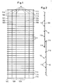
- the distances between the longitudinal bars 10 and also between the cross bars 11 are the same among themselves. Only in the edge parts was the distance between the first and second rod 111, 112 and between the last and penultimate rod 114, 115 doubled, or one transverse rod was omitted. Likewise, a longitudinal bar is missing in the middle of the mat between the middle bars 103, 104, so that there is at least a double bar spacing there.
- Fig. 3 shows a variant of a reinforcement mat for a reinforcement.
- the longitudinal bars 30 with the same lengths and the same cross-sectional area are evenly distributed at a distance 36.
- the cross bars are alternately arranged as long cross bars 31 and short cross bars 32.
- the two edge bars 33 are long cross bars and there is a double spacing 34 up to the next short cross bar 31.
- the longitudinal bars 30 and the transverse bars 31, 32 and 33 each have the same cross-sectional areas.
- the distribution of the cross bars 31, 32 in the field takes place taking into account the same distances 35.
- reinforcement meshes can be used
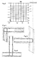
- Fig. 1 in the area of the large distance between the third and fourth longitudinal rod are bent twice by 90 °.
- These U-shaped structures can be pushed into one another with their webs in such a way that they at least partially penetrate one another and form a reinforcement arrangement for a corner, the legs of the U each providing the connecting parts for the wall reinforcements.
- FIG. 5 Another application variant is shown in FIG. 5 as reinforcement for a false ceiling.
- the reinforcement mat is bent twice by 90 ° in the middle between the third and fourth longitudinal bars, in such a way that a U-shaped structure is created.
- a favorable corner combination can be formed without having to separate reinforcement mats or using reinforcing bars in their place. If instead of a whole and double-curved reinforcement mat, one is cut lengthwise and the resulting edges are then bent over, mats for supporting reinforcements are created in the manner of connection iron.
- FIG. 6 An additional variant is shown in FIG. 6.
- a ceiling reinforcement with a halved and curved reinforcement mat according to FIG. 1 is shown as connecting iron for a wall.
- the outer dimensions for a mat according to FIG. 1 were defined in a customary form 2000 x 5000 mm. With a total of 32 crossbars 11 and a 25 mm overhang, this results in a bar spacing in the peripheral area of 300 mm and in the rest of the field of 29 x 150 mm. For the longitudinal bars 10, the bars are arranged at a distance of 300 mm at overhangs of 75 mm, so that there is a distance of 650 mm in the central region.
- 13 rods of the support reinforcement and 7 rods of the distribution reinforcement are provided.
- the two types of support arm have a length of 2500 mm and 2000 mm; this results in overhangs of 350 or 100 mm.
- the bars of the distribution reinforcement are evenly spaced from 300 mm and the bars of the support armouring with 150 mm, or at the edge with 300 mm, whereby in this dimension there are overhangs of 25 mm.
- the external dimensions here are 2500 mm to 2150 mm. Due to the different lengths of the rods for the support reinforcement, remarkable weight savings can be achieved, because a protrusion of 350 mm is sufficient for every second rod in the course of the moment of the support reinforcement.
Landscapes
- Engineering & Computer Science (AREA)
- Architecture (AREA)
- Civil Engineering (AREA)
- Structural Engineering (AREA)
- Reinforcement Elements For Buildings (AREA)
Applications Claiming Priority (2)
| Application Number | Priority Date | Filing Date | Title |
|---|---|---|---|
| AT3911/80 | 1980-07-28 | ||
| AT391180A AT368575B (de) | 1980-07-28 | 1980-07-28 | Bewehrungsmatte |
Publications (3)
| Publication Number | Publication Date |
|---|---|
| EP0045283A2 true EP0045283A2 (fr) | 1982-02-03 |
| EP0045283A3 EP0045283A3 (en) | 1982-03-17 |
| EP0045283B1 EP0045283B1 (fr) | 1983-09-07 |
Family
ID=3557112
Family Applications (1)
| Application Number | Title | Priority Date | Filing Date |
|---|---|---|---|
| EP19810810308 Expired EP0045283B1 (fr) | 1980-07-28 | 1981-07-27 | Treillis d'armature et son application |
Country Status (3)
| Country | Link |
|---|---|
| EP (1) | EP0045283B1 (fr) |
| AT (1) | AT368575B (fr) |
| DE (1) | DE3160849D1 (fr) |
Cited By (2)
| Publication number | Priority date | Publication date | Assignee | Title |
|---|---|---|---|---|
| EP1741851A1 (fr) * | 2005-07-04 | 2007-01-10 | Ruwa-Drahtschweisswerk Ag | Grillage d'armature pour béton armé et procédé pour la fabrication d'une armature de paroi |
| EP2130989A1 (fr) * | 2008-06-02 | 2009-12-09 | AVI Alpenländische Veredelungs-Industrie Gesellschaft m.b.H. | Treillis d'armature pour béton armé avec au moins une partie de débordement |
Family Cites Families (2)
| Publication number | Priority date | Publication date | Assignee | Title |
|---|---|---|---|---|
| DE1759587A1 (de) * | 1961-11-16 | 1971-01-28 | Friedrich Meissner | Bewehrungsanordnung fuer flaechige Betonbauteile |
| AT346046B (de) * | 1970-06-10 | 1978-10-25 | Tor Isteg Steel Corp | Bewehrung fuer stahlbetonkonstruktionen |
-
1980
- 1980-07-28 AT AT391180A patent/AT368575B/de not_active IP Right Cessation
-
1981
- 1981-07-27 DE DE8181810308T patent/DE3160849D1/de not_active Expired
- 1981-07-27 EP EP19810810308 patent/EP0045283B1/fr not_active Expired
Cited By (2)
| Publication number | Priority date | Publication date | Assignee | Title |
|---|---|---|---|---|
| EP1741851A1 (fr) * | 2005-07-04 | 2007-01-10 | Ruwa-Drahtschweisswerk Ag | Grillage d'armature pour béton armé et procédé pour la fabrication d'une armature de paroi |
| EP2130989A1 (fr) * | 2008-06-02 | 2009-12-09 | AVI Alpenländische Veredelungs-Industrie Gesellschaft m.b.H. | Treillis d'armature pour béton armé avec au moins une partie de débordement |
Also Published As
| Publication number | Publication date |
|---|---|
| EP0045283A3 (en) | 1982-03-17 |
| EP0045283B1 (fr) | 1983-09-07 |
| DE3160849D1 (en) | 1983-10-13 |
| ATA391180A (de) | 1982-02-15 |
| AT368575B (de) | 1982-10-25 |
Similar Documents
| Publication | Publication Date | Title |
|---|---|---|
| DE2922166C2 (fr) | ||
| DE69204449T2 (de) | Saum für gewebe. | |
| EP0045283A2 (fr) | Treillis d'armature et son application | |
| DE1484116C3 (de) | Bewehrungsmattenreihe | |
| DE3210680C2 (fr) | ||
| DE2402000C3 (de) | Bewehrungsmatte für Stahlbetonbauteile | |
| DE479871C (de) | Doppelte Metallbewehrung fuer Betonbauwerke aus vorbereiteten Gittergeflechten | |
| EP0067266A1 (fr) | Treillis d'armature pour la flexion bidimensionelle et procédé pour sa disposition | |
| EP0143101B1 (fr) | Armature pour constructions de béton armé | |
| CH648374A5 (en) | Reinforcing mat and use of the same | |
| AT371524B (de) | Bewehrungselement und verfahren zu dessen verlegung | |
| EP0045284A2 (fr) | Elément d'armature, son procédé de montage et application dudit élément | |
| DE2128383A1 (de) | Bewehrung für Stahlbetonkonstruktionen | |
| DE2510155C2 (de) | Bewehrungsmattenreihe | |
| DE2805683A1 (de) | Gelenkstuetztraeger fuer markisen | |
| DE2806228A1 (de) | Bewehrungsgebilde | |
| DE1918158A1 (de) | Reihe von streifenfoermigen Bewehrungsmatten | |
| CH647834A5 (en) | Reinforcing element for reinforced-concrete sheet-like load-bearing structures for bending in one direction or two directions, process for laying the element and use thereof | |
| AT378216B (de) | Bewehrungsmatte fuer stahlbeton | |
| DE19909517A1 (de) | Betonstahlmattenreihe und Bewehrungsanordnung mit Betonstahlmatten dieser Reihe | |
| DE1132311B (de) | Bewehrungsanordnung fuer Flaechentragwerke mit Bewehrungsgittern | |
| CH636395A5 (en) | Connection for wooden load-bearing members | |
| AT218216B (de) | Punktgeschweißte Bewehrungsmatte für flächenartige Bauteile aus Stahlbeton | |
| DE102022100925A1 (de) | Formstein für die Verlegung einer Erdreichabdeckung | |
| EP0176815A2 (fr) | Ecarteur pour des constructions en béton armé |
Legal Events
| Date | Code | Title | Description |
|---|---|---|---|
| PUAI | Public reference made under article 153(3) epc to a published international application that has entered the european phase |
Free format text: ORIGINAL CODE: 0009012 |
|
| PUAL | Search report despatched |
Free format text: ORIGINAL CODE: 0009013 |
|
| AK | Designated contracting states |
Designated state(s): BE CH DE FR GB IT LU NL SE |
|
| AK | Designated contracting states |
Designated state(s): BE CH DE FR GB IT LU NL SE |
|
| 17P | Request for examination filed |
Effective date: 19820225 |
|
| ITF | It: translation for a ep patent filed | ||
| GRAA | (expected) grant |
Free format text: ORIGINAL CODE: 0009210 |
|
| AK | Designated contracting states |
Designated state(s): BE CH DE FR GB IT LI LU NL SE |
|
| PG25 | Lapsed in a contracting state [announced via postgrant information from national office to epo] |
Ref country code: NL Effective date: 19830907 Ref country code: BE Effective date: 19830907 |
|
| REF | Corresponds to: |
Ref document number: 3160849 Country of ref document: DE Date of ref document: 19831013 |
|
| ET | Fr: translation filed | ||
| NLV1 | Nl: lapsed or annulled due to failure to fulfill the requirements of art. 29p and 29m of the patents act | ||
| PGFP | Annual fee paid to national office [announced via postgrant information from national office to epo] |
Ref country code: FR Payment date: 19840615 Year of fee payment: 4 |
|
| PGFP | Annual fee paid to national office [announced via postgrant information from national office to epo] |
Ref country code: DE Payment date: 19840622 Year of fee payment: 4 |
|
| PLBE | No opposition filed within time limit |
Free format text: ORIGINAL CODE: 0009261 |
|
| STAA | Information on the status of an ep patent application or granted ep patent |
Free format text: STATUS: NO OPPOSITION FILED WITHIN TIME LIMIT |
|
| PG25 | Lapsed in a contracting state [announced via postgrant information from national office to epo] |
Ref country code: SE Effective date: 19840728 |
|
| PG25 | Lapsed in a contracting state [announced via postgrant information from national office to epo] |
Ref country code: LU Free format text: LAPSE BECAUSE OF NON-PAYMENT OF DUE FEES Effective date: 19840731 |
|
| 26N | No opposition filed | ||
| GBPC | Gb: european patent ceased through non-payment of renewal fee | ||
| PG25 | Lapsed in a contracting state [announced via postgrant information from national office to epo] |
Ref country code: FR Free format text: LAPSE BECAUSE OF NON-PAYMENT OF DUE FEES Effective date: 19860328 |
|
| PG25 | Lapsed in a contracting state [announced via postgrant information from national office to epo] |
Ref country code: DE Effective date: 19860402 |
|
| REG | Reference to a national code |
Ref country code: FR Ref legal event code: ST |
|
| PG25 | Lapsed in a contracting state [announced via postgrant information from national office to epo] |
Ref country code: GB Effective date: 19881118 |
|
| PGFP | Annual fee paid to national office [announced via postgrant information from national office to epo] |
Ref country code: CH Payment date: 19890706 Year of fee payment: 9 |
|
| PG25 | Lapsed in a contracting state [announced via postgrant information from national office to epo] |
Ref country code: LI Effective date: 19900731 Ref country code: CH Effective date: 19900731 |
|
| REG | Reference to a national code |
Ref country code: CH Ref legal event code: PL |
|
| EUG | Se: european patent has lapsed |
Ref document number: 81810308.7 Effective date: 19850617 |