EP0045380A2 - Circuit de commande pour un dispositif de réglage et de dressage d'une meule - Google Patents
Circuit de commande pour un dispositif de réglage et de dressage d'une meule Download PDFInfo
- Publication number
- EP0045380A2 EP0045380A2 EP81105183A EP81105183A EP0045380A2 EP 0045380 A2 EP0045380 A2 EP 0045380A2 EP 81105183 A EP81105183 A EP 81105183A EP 81105183 A EP81105183 A EP 81105183A EP 0045380 A2 EP0045380 A2 EP 0045380A2
- Authority
- EP
- European Patent Office
- Prior art keywords
- grinding wheel
- displacement sensor
- output
- counter
- comparator
- Prior art date
- Legal status (The legal status is an assumption and is not a legal conclusion. Google has not performed a legal analysis and makes no representation as to the accuracy of the status listed.)
- Granted
Links
Images


Classifications
-
- B—PERFORMING OPERATIONS; TRANSPORTING
- B24—GRINDING; POLISHING
- B24B—MACHINES, DEVICES, OR PROCESSES FOR GRINDING OR POLISHING; DRESSING OR CONDITIONING OF ABRADING SURFACES; FEEDING OF GRINDING, POLISHING, OR LAPPING AGENTS
- B24B49/00—Measuring or gauging equipment for controlling the feed movement of the grinding tool or work; Arrangements of indicating or measuring equipment, e.g. for indicating the start of the grinding operation
- B24B49/18—Measuring or gauging equipment for controlling the feed movement of the grinding tool or work; Arrangements of indicating or measuring equipment, e.g. for indicating the start of the grinding operation taking regard of the presence of dressing tools
Definitions
- the invention relates to a control circuit of the type specified in the preamble of claim 1 for a device for adjusting and dressing a grinding wheel.
- a control circuit which has a push button contact attached to a push button. The button is placed intermittently on the ring surface, and as soon as the contact is closed due to some wear of the ring surface, the control circuit issues a command to readjust the grinding wheel.
- the adjustment takes place around one tooth of a ratchet wheel, by means of which the grinding spindle is adjusted. If a preselected number of readjustments is not reached within the preselectable dressing interval, this is regarded as an indication that the surface of the grinding wheel is smeared (clogging of its pores by grinding dust, oil, etc.) and that work is not done properly within the dressing interval Has. In this case, the control circuit therefore delivers a further command, by means of which the dressing tool is moved by one tooth of another ratchet wheel and the dressing tool is then pivoted over the ring surface of the grinding wheel for dressing.
- the scanning is only intended for readjusting the grinding wheel, since the dressing process always remains the same and is only carried out if the preselected number of grinding wheel readjustments is not reached within a dressing interval. It is therefore in need of improvement that the scanning process provides no information about the quality of the grinding wheel, that is to say nothing about the appearance of its grinding surface, and that during the dressing process the same amount of material is always removed from the grinding wheel without knowing whether one such material removal is required at all. Since the tactile contact only provides YES / No information (ie readjust or not readjust), it cannot be determined how far the grinding spindle is to be readjusted, which is why in the known device the grinding spindle is simply always advanced by one tooth. Whether such a transition was sufficient or too large then can only be determined in the next sampling interval.
- the grinding wheel must therefore be adjusted in the radial direction so that its outer surface can be dressed by another dressing device.
- the known device provides no information about when this radial adjustment of the grinding wheel and thus the dressing of its outer surface has to take place.
- the object of the invention is to provide a control circuit of the type specified in the preamble of claim 1 for a device for adjusting and dressing a grinding wheel in such a way that it indicates the actual wear condition of the grinding wheel and its surface condition and only one readjustment and / or dressing process when it is actually required and only initiates to the extent necessary.
- control circuit equipped with a touch contact is only able to indicate whether the grinding wheel is worn or not worn and thus can be adjusted or not adjusted
- the control circuit according to the invention delivers considerably more due to the displacement sensor used instead of the touch contact by the scanning process Information by means of which a statement can be made about the quality of the surface of the grinding wheel.
- the displacement sensor delivers pulsating signals, from the peak number and effective value of which the information required for adjusting and dressing the grinding wheel can be obtained with the aid of simple pulse shaping and integrating circuits.
- the counter reading of the first counter corresponds to the number of pulses during a key interval.
- this counter reading can be used as a statement about the surface quality of the wheel, e.g. Grinding dust, oil, etc. clog the pores of the disc and therefore deliver fewer impulses. It is therefore possible to dress the grinding wheel only when dressing is really necessary and also to adjust the stroke of the dressing tool accordingly.
- control circuit provides a wear signal, on the basis of which it can be precisely determined when, how far and how often the grinding wheel is to be adjusted in the axial direction.
- control circuit supplies a signal which corresponds to the number of axial readjustments and precisely states when the grinding wheel is to be radially adjusted and dressed, i.e. when their outer surface has to be turned off.
- control circuit supplies a signal which indicates from when a grinding wheel has been turned so far that it can no longer be used.
- a button 2 corresponds to the button designated by the reference number 15 in FIG. 1 of DE-OS 27 26 843.
- the button 2 is pivotally mounted at point 3. At its right end, it carries a tactile diamond 4, which is brought into contact with an annular surface 1a of the grinding wheel 1 when the stylus 2 is pivoted.
- An actuating device 5 acts on the lever arm 2b of the pushbutton 2 to the left of the pivot bearing 3
- Touch diamond 4 periodically presses on the grinding wheel, so that an operative connection 6 acts at the other end on an element provided inside a displacement sensor 7 in the manner described in detail below.
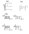
- the button 2 is periodically pivoted by the actuating device 5 so that the touch diamond touches the grinding wheel for a short time t T and is then lifted off again, as shown in FIG. 2, in which the interval "buttons" (t T ) for example 0.3 s and the "off-hook” interval is 0.7 s. This avoids unnecessary wear of the grinding wheel by the tactile diamond.
- the short swivel path of the lever arm 2a is converted into a substantially longer swivel path of the lever arm 2b and into a corresponding translation movement on the operative connection 6.
- a displacement sensor is used in the control circuit described here, which can be an inductive, a capacitive or an optical displacement sensor.
- Such a position sensor is able to supply a continuous signal dependent on the path of the touch diamond instead of the YES / NO information of the known touch contact.
- the embodiment of the control circuit described here is explained using the example of the use of an inductive displacement sensor. This can have the structure shown schematically in FIG. 3, for example.
- a reciprocating iron core 71 is arranged, the position of which influences the magnetic field of the coils and thus the output signal of the displacement sensor, which is picked up at the connection point of the two coils and the other end point of one or the other coil , while the supply voltage of the encoder is connected to the terminals labeled "+" and "-".
- the position of the iron core 71 is due to the operative connection 6, in which it the exemplary embodiment described here is a mechanical connection, depending on the position of the tactile diamond 4. Unevenness of the grinding wheel 1 in the order of 1 ⁇ m already causes the touch diamond 4 and thus the displacement sensor 7 to respond.
- the displacement sensor 7 emits an output signal which has one of the signal forms shown in FIGS. 4a-4d.
- 4a shows a voltage signal, the shape of which corresponds to the oscillations of the tactile diamond, which the diamond executes when it follows the grinding wheel surface and is deflected in each case by abrasive grains or generally by unevenness.
- This signal corresponds to a small wear of the grinding wheel and a rough, ie open-pore grinding wheel surface.
- the signal shown in Fig. 4b corresponds to a small wear of the grinding wheel and a smooth surface, the pores of which are clogged, for example by grinding dust and oil.
- the peaks of this signal are each wider in time, since the tactile diamond is deflected less frequently by an abrasive grain protruding from the surface of the grinding wheel.
- the signal shown in Fig. 4c corresponds to a large wear of the grinding wheel and a rough surface. Due to the greater wear of the grinding wheel compared to the case in FIG. 4a, the tactile diamond had to travel a greater distance, the iron core 71 in the displacement sensor 7 being correspondingly displaced further upward. The probe diamond 4 or the iron core 71 then carries out the same oscillations around this upper layer as in the case of FIG. 4a. As a result, the signal in Fig. 4c has a larger RMS value than the signal in Fig. 4a.
- the signal shown in Fig. 4d corresponds to a large wear of the grinding wheel and a smooth grinding wheel surface. For the reasons set out above, too the signal in FIG. 4d has a larger effective value than the signal in FIG. 4b.
- the position sensor 4 is followed by three circuit branches, designated I, II and III, of the control circuit, which are described in detail below.
- circuit branch I the output of the displacement sensor 7 is connected to a comparator 8, the output of which is connected to the input of a counter 9.
- the output of the counter 9 is connected to the input of a comparator 10, the second input of which is connected to a constant encoder 11.
- the output of the comparator 10 is connected to a terminal A I.
- the set input S and the reset input R of the counter 9 are connected to the actuating device 5.
- the circuit branch I evaluates output signals of the displacement sensor 7 of the type shown in FIGS. 4a and 4b as follows:
- the comparator (pulse shaper) 8 is triggered each time the rising signal edges reach a value V 1 , so that it outputs a corresponding pulse to the counter 9.
- the actuating device 5 contains, for example, an asynchronous motor which drives a cam disk via a reduction gear, via which the button 2 is pivoted for the button time t T in each sampling interval. At the beginning of each sampling interval, the actuating device emits an enable signal to the input S of the counter 9, as a result of which the counter 9 is set and is thereby able to count the pulses supplied to it by the comparator 8 during the sampling time t. At the end of time t, counter 9 is reset by a reset signal supplied to it by actuating device 5 via input R, and the counting process is thereby ends.
- the counter reading is given to the comparator 10, which compares it with a constant.
- the constant supplied by the constant encoder 11 is a value that is specific to each grinding wheel and is dependent on the grinding wheel grit.
- the constant is set for each grinding wheel in the constant encoder 11. This constant can be determined and determined on a new grinding wheel by measurement using the circuit described here.
- the counter 9 counts the number of peaks of the signal of FIG. 4a or 4b on the basis of the pulses supplied to it by the comparator 8 during the scanning time t T. As an example for the case shown in FIG. 4a, it is assumed that a new grinding wheel produced ten signal peaks in the sampling time t. The number "10" would therefore be set in the constant generator 11.
- This value "10" is compared with the number of pulses supplied by the counter. If the comparator determines that the grinding wheel constant and the count are the same, it means that the grinding wheel is OK and no dressing is required. If, on the other hand, the comparator determines that the number of pulses supplied by the counter is somewhat smaller than the constant and, for example, according to FIG. 4a, it is "6", this means a small wear on the grinding wheel and a rough grinding wheel surface. If the comparison result indicates that the number of pulses of the counter 9 is significantly smaller than the constant, this means a small wear of the grinding wheel and a smooth grinding wheel surface (Fig. 4b). Since a smooth grinding wheel surface is disadvantageous, a dressing process is triggered in this case via the signal output at terminal A I.
- Circuit branch I enables the control circuit not only to trigger a dressing process, but also to determine the stroke of the dressing tool. This represents a much more precise dressing process than in the known device, since it is in regular use Time intervals and always dressing with the same stroke. The latter is particularly disadvantageous in the case of panes which are only used for finishing, ie which have a significantly longer service life due to significantly less wear.
- the control circuit according to the invention is much more advantageous since it only initiates a dressing process when a smooth (ie smeared) grinding wheel surface has actually been found.
- the signal output at terminal A is fed to a dressing device (not shown in FIG. 1) which can be continuously adjusted in accordance with the size of this signal. After this adjustment has been made, the dressing diamond carries out the dressing process as in the known device.
- circuit branch I only the number of vertices of the output signal of displacement sensor 7 is of interest, since this number, based on the comparison with the grinding wheel constant, enables a statement about the surface condition of the grinding wheel.
- the amplitude of the apex is additionally evaluated in circuit branch II, since when the grinding wheel is very worn, it has an apex value V 2 which is greater than V 1 .
- the circuit branch II contains an integrator 12, the input of which is connected to the output of the displacement sensor 7 and the output of which is connected to an output terminal A II .
- the integrator 12 integrates the output signal of the displacement sensor over the pulse time t T and delivers an integration result as a wear signal at the terminal A II .
- the rms voltage value of this signal is an immediate indication of how much the grinding wheel is worn and how far the grinding spindle has to be readjusted.
- the wear signal emitted at output A II is fed to a continuously variable adjustment drive for the grinding spindle.
- the circuit branch II makes it possible to determine this adjustment that is too wide, because the iron core 71 of the inductive displacement sensor 7 is pulled further out of the magnetic field and then the rms voltage value formed by the integrator is significantly smaller than in the case of a rough surface with the correct grinding wheel position. In this case, the grinding wheel can be automatically reset to the correct position.
- the circuit branch III contains an A / D converter 13, the input of which is connected to the output of the integrator 12 and the output of which is connected to the input of a comparator 14.
- the A / D converter 13 outputs a number of digital values corresponding to the voltage supplied by the integrator 12, which the comparator 14 compares with a constant, which it receives from a constant generator 15 via a further input.
- the comparator 14 outputs the comparison result as an output signal at a terminal A III .
- the constant to be entered in the constant encoder 15 for each new grinding wheel is determined as follows:
- wear and tear of the grinding wheel is indicated with vertical dashed lines, each of which requires readjustment because the wheel becomes increasingly thinner due to wear and dressing, ie its ring surface 1 a moves further and further to the right in FIG.
- the grinding wheel measured on its lateral surface ld, has become so thin that, for example when grinding very large teeth, there is a risk that the grinding wheel will be pushed away by the workpiece during the grinding process. It is therefore after a certain number of readjustments, it is necessary to machine the outer surface 1d.
- This processing consists in turning the outer surface by the dimension Y with the help of a dressing diamond.
- the constant for the constant generator 15 can therefore be determined so that, for example after 15 ⁇ m adjustment (wear dimension 1c), the outer surface must be turned once by Y so that the grinding wheel regains its original strength at its grinding point 1b.
- the degree of wear 1c is therefore entered into the constant generator 15. Since the original thickness of the grinding wheel is known, it can be determined with the aid of the signal given at the terminal A III how far the wheel on the ring surface 1a has already been worn and when the turning by the dimension Y has to be carried out.
- the comparator 14 compares the constant from the constant generator 15 with the value from the A / D converter and, if the result exceeds a certain value, the disk on the jacket is turned off by the dimension Y. For this purpose, the grinding spindle with the grinding wheel in FIG. 5 is moved upward by the dimension Y in response to the signal output at the terminal A III , the calibration diamond moves over the outer surface of the wheel and wears it off by the dimension Y.
- a counter 16 is connected to the output of circuit branch III, the output of which is connected to an input of a comparator 17.
- the comparator 17 has a further input which is connected to a constant generator 18.
- the output of the comparator 17 is connected to a terminal A ' III .
- the counter 16 counts the output pulses of the comparator 14.
- the counter reading is compared in the comparator 17 with the constant set in the constant generator 18. This constant indicates how often the dimension Y can be turned off until the disc can no longer be used. If the comparator 17 determines that the counter reading of the counter 16 and that of the constant supplied 18 constant are the same, the grinding machine is switched off via the signal output at the terminal A ' III , since the grinding wheel must be replaced. In this case, the counter 16 is also cleared to zero again via a reset input (not shown).
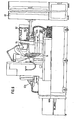
- F ig. 6 shows an overall view of a gear grinding machine in which the control circuit described here is used.
- the control circuit is accommodated in an electronics cabinet 61 arranged next to the machine.
- An operating panel 62 carries the setting devices for the constant transmitters 11, 15 and 18.
- 63a and 63b denote the feed cylinders for the two grinding wheels of the machine.
- the drive motor is one of the two feed carriages for the axial grinding spindle adjustment.
Landscapes
- Engineering & Computer Science (AREA)
- Mechanical Engineering (AREA)
- Grinding-Machine Dressing And Accessory Apparatuses (AREA)
- Constituent Portions Of Griding Lathes, Driving, Sensing And Control (AREA)
Applications Claiming Priority (2)
| Application Number | Priority Date | Filing Date | Title |
|---|---|---|---|
| CH583580 | 1980-07-31 | ||
| CH5835/80 | 1980-07-31 |
Publications (3)
| Publication Number | Publication Date |
|---|---|
| EP0045380A2 true EP0045380A2 (fr) | 1982-02-10 |
| EP0045380A3 EP0045380A3 (en) | 1982-06-02 |
| EP0045380B1 EP0045380B1 (fr) | 1984-10-24 |
Family
ID=4300086
Family Applications (1)
| Application Number | Title | Priority Date | Filing Date |
|---|---|---|---|
| EP81105183A Expired EP0045380B1 (fr) | 1980-07-31 | 1981-07-04 | Circuit de commande pour un dispositif de réglage et de dressage d'une meule |
Country Status (4)
| Country | Link |
|---|---|
| US (1) | US4461125A (fr) |
| EP (1) | EP0045380B1 (fr) |
| JP (1) | JPS5754075A (fr) |
| DE (2) | DE3039130C2 (fr) |
Cited By (2)
| Publication number | Priority date | Publication date | Assignee | Title |
|---|---|---|---|---|
| EP0131743A3 (en) * | 1983-06-16 | 1987-04-15 | Coburn Optical Industries, Inc. | Calibration gauge for computer-controlled lens generator or the like |
| WO1998000264A1 (fr) * | 1996-07-01 | 1998-01-08 | Vollmer Werke Maschinenfabrik Gmbh | Machine pour l'usinage des flancs des dents d'un outil de coupe |
Families Citing this family (12)
| Publication number | Priority date | Publication date | Assignee | Title |
|---|---|---|---|---|
| DE3315197A1 (de) * | 1983-04-27 | 1984-10-31 | Schaudt Maschinenbau Gmbh, 7000 Stuttgart | Verfahren zum abrichten von schleifscheiben |
| JPS6033006A (ja) * | 1983-08-02 | 1985-02-20 | Toyoda Mach Works Ltd | 円筒型砥石車のツル−イング装置 |
| DE3529427A1 (de) * | 1985-08-16 | 1987-02-26 | Fortuna Werke Maschf Ag | Verfahren und vorrichtung zum einleiten eines abrichtvorganges einer schleifscheibe in abhaengigkeit von deren stumpfungsgrad |
| US4604834A (en) * | 1985-10-03 | 1986-08-12 | General Electric Company | Method and apparatus for optimizing grinding |
| US5025592A (en) * | 1988-05-09 | 1991-06-25 | Brother Kogyo Kabushiki Kaisha | Machine tool having workpiece machining dimension and tool length measuring functions |
| CA1276470C (fr) * | 1988-06-30 | 1990-11-20 | Suren B. Rao | Methode d'optimisation et dispositif de dressage de meules |
| US4924842A (en) * | 1988-06-30 | 1990-05-15 | National Broach & Machine Company | Optimization method and apparatus for dressing a grinding wheel |
| DE10104287B4 (de) * | 2001-01-30 | 2006-08-24 | Sirona Dental Systems Gmbh | Verfahren zur Bestimmung aktueller Positionsdaten eines Bearbeitungswerkzeuges und Vorrichtung hierzu |
| US20170066104A9 (en) * | 2009-12-08 | 2017-03-09 | Allison Transmission Inc. | Method for Detecting And/Or Preventing Grind Burn |
| JP5573459B2 (ja) * | 2010-07-27 | 2014-08-20 | 株式会社ジェイテクト | 研削方法および研削盤 |
| CN112439951B (zh) * | 2020-11-11 | 2022-03-11 | 中国航发中传机械有限公司 | 一种基于几何自适应补偿的齿轮倒圆倒角铣削加工方法 |
| CN113927482B (zh) * | 2021-10-18 | 2023-04-11 | 广汽乘用车有限公司 | 一种伺服焊钳电极修磨压力控制方法及控制系统 |
Family Cites Families (16)
| Publication number | Priority date | Publication date | Assignee | Title |
|---|---|---|---|---|
| CH89285A (de) * | 1920-08-06 | 1921-09-16 | Fleischmann Nikolaus | Vorrichtung zum selbsttätigen Nachstellen einer Schleifscheibe behufs Ausgleichens ihrer Abnützung. |
| GB481021A (en) * | 1936-08-31 | 1938-02-28 | Maag Zahnraeder & Maschinen Ag | Device for adjusting the grinding disc of grinding machines, more particularly gear grinding machines |
| US3033187A (en) * | 1961-03-13 | 1962-05-08 | Norton Co | Wheel wear sensing device and compensator |
| US3214965A (en) * | 1962-05-31 | 1965-11-02 | Abrasive Dressing Tool Company | Inspecting abrasive grinding wheels |
| DE1302454B (fr) * | 1964-07-08 | |||
| GB1053140A (fr) * | 1965-12-20 | |||
| US3517460A (en) * | 1966-04-26 | 1970-06-30 | Donald R Stewart | Abrading tool control systems |
| US3500811A (en) * | 1966-08-26 | 1970-03-17 | Gen Motors Corp | Automatically controlled dressing apparatus for a grinding wheel |
| US3691698A (en) * | 1970-11-23 | 1972-09-19 | Sundstrand Engelberg | Abrasive element dimension sensing mechanism |
| JPS48101151A (fr) * | 1972-04-04 | 1973-12-20 | ||
| DD96043A1 (fr) * | 1972-04-07 | 1973-03-12 | ||
| DE2535912A1 (de) * | 1975-08-12 | 1977-02-17 | Salje Ernst | Verfahren und vorrichtung zur rauhigkeitspruefung von oberflaechen |
| DD122662A1 (fr) * | 1975-10-28 | 1976-10-20 | ||
| SU544542A2 (ru) * | 1976-01-19 | 1977-01-30 | Центральный Научно-Исследовательский И Конструкторский Институт Топливной Аппаратуры Автотракторных И Стационарных Двигателей | Устройство дл правки шлифовальных кругов |
| CH617380A5 (fr) * | 1977-05-05 | 1980-05-30 | Maag Zahnraeder & Maschinen Ag | |
| US4295301A (en) * | 1979-11-08 | 1981-10-20 | Trw Inc. | Dressing apparatus with means for detecting grinding wheel wear |
-
1980
- 1980-10-16 DE DE3039130A patent/DE3039130C2/de not_active Expired
-
1981
- 1981-07-04 EP EP81105183A patent/EP0045380B1/fr not_active Expired
- 1981-07-04 DE DE8181105183T patent/DE3166817D1/de not_active Expired
- 1981-07-20 US US06/284,971 patent/US4461125A/en not_active Expired - Fee Related
- 1981-07-28 JP JP56117216A patent/JPS5754075A/ja active Pending
Cited By (2)
| Publication number | Priority date | Publication date | Assignee | Title |
|---|---|---|---|---|
| EP0131743A3 (en) * | 1983-06-16 | 1987-04-15 | Coburn Optical Industries, Inc. | Calibration gauge for computer-controlled lens generator or the like |
| WO1998000264A1 (fr) * | 1996-07-01 | 1998-01-08 | Vollmer Werke Maschinenfabrik Gmbh | Machine pour l'usinage des flancs des dents d'un outil de coupe |
Also Published As
| Publication number | Publication date |
|---|---|
| DE3039130A1 (de) | 1982-02-11 |
| US4461125A (en) | 1984-07-24 |
| DE3039130C2 (de) | 1982-12-09 |
| DE3166817D1 (en) | 1984-11-29 |
| EP0045380A3 (en) | 1982-06-02 |
| JPS5754075A (fr) | 1982-03-31 |
| EP0045380B1 (fr) | 1984-10-24 |
Similar Documents
| Publication | Publication Date | Title |
|---|---|---|
| DE3039467C2 (fr) | ||
| DE2635766C2 (de) | Verfahren und Vorrichtung zur Funkenerosionsbearbeitung | |
| EP0045380B1 (fr) | Circuit de commande pour un dispositif de réglage et de dressage d'une meule | |
| EP0390938A1 (fr) | Procédé et dispositif pour le rodage d'alésages | |
| EP0372258B1 (fr) | Procédé et dispositif de réglage d'une largeur de balayage présélectionnée d'un balai rotatif cylindrique | |
| DE2051680A1 (de) | Schleifmaschine mit automatischer Steuerung der Vorschubgeschwindigkeit des Schleif Spindelschlittens | |
| DE3818159C2 (fr) | ||
| EP1919658A1 (fr) | Dispositif d'usinage avec dispositif de mesure pour un modele | |
| EP0459224B1 (fr) | Méthode d'actionnement d'une presse | |
| DE2443383B2 (de) | Regeleinrichtung für die Schleifschlitten-Zustellgeschwindigkeit an Rundschleifmaschinen | |
| DE2360073C3 (de) | Rundschleifmaschine | |
| DE3315197A1 (de) | Verfahren zum abrichten von schleifscheiben | |
| DE4012660C2 (fr) | ||
| DE2644890C2 (de) | Abrichtgerät für tellerförmige Schleifscheiben an einer Zahnflankenschleifmaschine | |
| EP0131107A2 (fr) | Dispositif d'encrage pour une machine d'impression | |
| DE3634409A1 (de) | Vorrichtung zum bearbeiten von werkstuecken durch magnetabrasives schleifen | |
| EP0282776B1 (fr) | Procédé d'honage | |
| CH631913A5 (de) | Einrichtung zum steuern der zustellung einer schleifscheibe relativ zu einer abrichtvorrichtung. | |
| DE3105578C2 (de) | Vorrichtung zum Positionieren einer Schleifscheibe | |
| DE2702845A1 (de) | Elektronische steuervorrichtung fuer schleifmaschinen, basierend auf der positionsbestimmung des diamanten bezueglich des werkstuecks | |
| DE4131679C1 (fr) | ||
| DE4436582C2 (de) | Verfahren zur Regelung einer Feuchtmittelmenge für eine Druckform einer laufenden Offsetrotationsdruckmaschine | |
| DE3441458C2 (fr) | ||
| EP0292642B1 (fr) | Procédé et dispositif de commande d'un mécanisme de génération d'une machine à rectifier des roues dentées | |
| DE3838751C2 (fr) |
Legal Events
| Date | Code | Title | Description |
|---|---|---|---|
| PUAI | Public reference made under article 153(3) epc to a published international application that has entered the european phase |
Free format text: ORIGINAL CODE: 0009012 |
|
| AK | Designated contracting states |
Designated state(s): CH DE FR GB IT NL SE |
|
| PUAL | Search report despatched |
Free format text: ORIGINAL CODE: 0009013 |
|
| AK | Designated contracting states |
Designated state(s): CH DE FR GB IT NL SE |
|
| 17P | Request for examination filed |
Effective date: 19820907 |
|
| ITF | It: translation for a ep patent filed | ||
| GRAA | (expected) grant |
Free format text: ORIGINAL CODE: 0009210 |
|
| AK | Designated contracting states |
Designated state(s): CH DE FR GB IT LI NL SE |
|
| REF | Corresponds to: |
Ref document number: 3166817 Country of ref document: DE Date of ref document: 19841129 |
|
| ET | Fr: translation filed | ||
| PLBE | No opposition filed within time limit |
Free format text: ORIGINAL CODE: 0009261 |
|
| STAA | Information on the status of an ep patent application or granted ep patent |
Free format text: STATUS: NO OPPOSITION FILED WITHIN TIME LIMIT |
|
| 26N | No opposition filed | ||
| PGFP | Annual fee paid to national office [announced via postgrant information from national office to epo] |
Ref country code: NL Payment date: 19870731 Year of fee payment: 7 |
|
| PG25 | Lapsed in a contracting state [announced via postgrant information from national office to epo] |
Ref country code: GB Effective date: 19880704 |
|
| PG25 | Lapsed in a contracting state [announced via postgrant information from national office to epo] |
Ref country code: SE Effective date: 19880705 |
|
| PG25 | Lapsed in a contracting state [announced via postgrant information from national office to epo] |
Ref country code: LI Effective date: 19880731 Ref country code: CH Effective date: 19880731 |
|
| PG25 | Lapsed in a contracting state [announced via postgrant information from national office to epo] |
Ref country code: NL Effective date: 19890201 |
|
| GBPC | Gb: european patent ceased through non-payment of renewal fee | ||
| NLV4 | Nl: lapsed or anulled due to non-payment of the annual fee | ||
| PG25 | Lapsed in a contracting state [announced via postgrant information from national office to epo] |
Ref country code: FR Free format text: LAPSE BECAUSE OF NON-PAYMENT OF DUE FEES Effective date: 19890331 |
|
| REG | Reference to a national code |
Ref country code: CH Ref legal event code: PL |
|
| PG25 | Lapsed in a contracting state [announced via postgrant information from national office to epo] |
Ref country code: DE Effective date: 19890401 |
|
| REG | Reference to a national code |
Ref country code: FR Ref legal event code: ST |
|
| EUG | Se: european patent has lapsed |
Ref document number: 81105183.8 Effective date: 19890510 |