EP0390938A1 - Procédé et dispositif pour le rodage d'alésages - Google Patents
Procédé et dispositif pour le rodage d'alésages Download PDFInfo
- Publication number
- EP0390938A1 EP0390938A1 EP89105759A EP89105759A EP0390938A1 EP 0390938 A1 EP0390938 A1 EP 0390938A1 EP 89105759 A EP89105759 A EP 89105759A EP 89105759 A EP89105759 A EP 89105759A EP 0390938 A1 EP0390938 A1 EP 0390938A1
- Authority
- EP
- European Patent Office
- Prior art keywords
- honing
- honing tool
- working parts
- pressure
- bore wall
- Prior art date
- Legal status (The legal status is an assumption and is not a legal conclusion. Google has not performed a legal analysis and makes no representation as to the accuracy of the status listed.)
- Withdrawn
Links
Images
Classifications
-
- G—PHYSICS
- G05—CONTROLLING; REGULATING
- G05B—CONTROL OR REGULATING SYSTEMS IN GENERAL; FUNCTIONAL ELEMENTS OF SUCH SYSTEMS; MONITORING OR TESTING ARRANGEMENTS FOR SUCH SYSTEMS OR ELEMENTS
- G05B19/00—Program-control systems
- G05B19/02—Program-control systems electric
- G05B19/18—Numerical control [NC], i.e. automatically operating machines, in particular machine tools, e.g. in a manufacturing environment, so as to execute positioning, movement or co-ordinated operations by means of program data in numerical form
- G05B19/416—Numerical control [NC], i.e. automatically operating machines, in particular machine tools, e.g. in a manufacturing environment, so as to execute positioning, movement or co-ordinated operations by means of program data in numerical form characterised by control of velocity, acceleration or deceleration
- G05B19/4163—Adaptive control of feed or cutting velocity
-
- B—PERFORMING OPERATIONS; TRANSPORTING
- B24—GRINDING; POLISHING
- B24B—MACHINES, DEVICES, OR PROCESSES FOR GRINDING OR POLISHING; DRESSING OR CONDITIONING OF ABRADING SURFACES; FEEDING OF GRINDING, POLISHING, OR LAPPING AGENTS
- B24B33/00—Honing machines or devices; Accessories therefor
- B24B33/06—Honing machines or devices; Accessories therefor with controlling or gauging equipment
-
- Y—GENERAL TAGGING OF NEW TECHNOLOGICAL DEVELOPMENTS; GENERAL TAGGING OF CROSS-SECTIONAL TECHNOLOGIES SPANNING OVER SEVERAL SECTIONS OF THE IPC; TECHNICAL SUBJECTS COVERED BY FORMER USPC CROSS-REFERENCE ART COLLECTIONS [XRACs] AND DIGESTS
- Y02—TECHNOLOGIES OR APPLICATIONS FOR MITIGATION OR ADAPTATION AGAINST CLIMATE CHANGE
- Y02P—CLIMATE CHANGE MITIGATION TECHNOLOGIES IN THE PRODUCTION OR PROCESSING OF GOODS
- Y02P90/00—Enabling technologies with a potential contribution to greenhouse gas [GHG] emissions mitigation
- Y02P90/02—Total factory control, e.g. smart factories, flexible manufacturing systems [FMS] or integrated manufacturing systems [IMS]
Definitions
- the invention relates to a method for honing bores according to the preamble of patent claim 1 and a honing machine for performing the method according to the preamble of patent claim 11.
- a feed device is provided in the conventional honing machines, which moves the honing stones radially in the direction of the bore wall after the tool has been inserted into the bore and generates the contact pressure during processing.
- the feed device can be operated hydraulically or mechanically.
- a constant infeed force is generated in the hydraulic infeed systems.
- the mechanical infeed systems a certain infeed path is specified, with an infeed force being set that is dependent on the mechanical system and is not taken into account in the known methods for controlling the machining.
- the feed force concentrates on the respective contact surface of the honing stones on the bore wall. If this contact surface becomes smaller during processing, the surface pressure of the honing stones increases because the rigidity of the feed system does not allow the honing stones to retreat.
- a reduction in the contact surface and thus an increased surface pressure occurs, for example, in the area of recesses and openings in the bore wall and also at the bore ends, since the honing stones extend there with a portion of their length from the bore before they are retracted by reversing the stroke of the honing tool.
- the differences in surface pressure that occur during machining reduce the quality of the machined surface and lead to inaccurate shape of the workpiece.
- the invention has for its object to further develop the honing process and the honing machine of the known type such that the quality and accuracy of the machined bore wall, which is dependent on the surface pressure of the honing tool, are improved. Uneven wear of the working parts of the honing tool should also be reduced to a minimum.
- the object is achieved according to the invention in the known honing process with the characterizing feature of claim 1 and in the known honing machine with the characterizing features of claim 11.
- the inventive control of the pressure force, carried out during machining, with which the working parts of the honing tool are held on the bore wall, makes it possible to adapt the surface pressure of these working parts to the particular circumstances of the bore to be machined.
- the surface pressure can be kept constant, so that there is a uniform material removal over the entire bore length and regardless of any interruptions in the bore wall and thus a high dimensional accuracy of the finished bore is guaranteed. This also results in very uniform wear of the working parts, for example the honing stones or honing stones, which then have to be dressed less frequently.
- the size of the surface pressure can also be specifically varied during processing in order to achieve a specific work result.
- the electronic feed control device for the feed device of the honing tool working parts provided on the honing machine according to the invention enables automatic control of the pressure force with which the working parts are pressed against the bore wall during the lifting and rotating movement of the honing tool.
- the pressure force can be regulated to a predetermined setpoint or can also be controlled in accordance with an entered program. This also automates the honing process with regard to the pressure force to be controlled according to the invention, so that the honing machine works particularly economically.
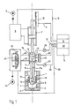
- the honing tool 1 shows a honing tool 1 of the program-controlled honing machine, not otherwise shown in detail, within the bore 3 of a workpiece 2, in the present case a two-stroke cylinder with a cylindrical bore.
- the bore wall 4 is interrupted by a plurality of channels 5 which open into the bore 3, that is to say into the interior of the cylinder 2, as can be seen from FIG. 1 and also from the development of the bore wall according to FIG. 2.
- the honing tool 1 is attached to a honing spindle 6, which is moved up and down in the direction of its longitudinal axis by a lifting drive, in the exemplary embodiment by a hydraulic lifting cylinder 7.
- the honing spindle is also set in rotation by a rotary drive (not shown).
- a travel sensor 10 is provided for the stroke reversal, which determines the altitude of the honing spindle 6 and emits digital or analog signals which are fed to a stroke control device 12 via an electrical line 11.
- the stroke control device 12 is part of a program control unit 14 of the numerically controlled honing machine (NC control).
- the predetermined stroke distance is stored in the program control unit 14, so that when certain values determined by the travel sensor 10 are reached, the stroke control device 12 emits a signal to the control unit 8 for reversing the stroke via a line 13. This type of stroke reversal is known per se.
- the honing tool 1 has honing bars 15 as working parts, which can be adjusted radially to the axis of the honing spindle 6.
- an infeed cone 18 is provided, which is displaceably guided on inclined surfaces of carriers of the honing stones 15 and is adjustable in the axial direction of the honing spindle 6 by means of an infeed device 16.
- the feed device consists of a piston-cylinder unit with a piston 17 located in the cylinder, to whose piston rod 17a the feed cone 18 is attached.
- the piston rod 17a is located centrally in the honing spindle 6.
- the control unit 23 contains a control valve 25.
- a pressure sensor 26 or 27 is also connected to the two pressure chambers 19 and 21 of the feed device 16 via a measuring line.
- An electrical line 31 leads from the pressure sensor 26 to a measurement input of an electronic delivery control device 30, which is part of the program control unit 14.
- An electrical line 32 which is connected to the pressure sensor 27, leads to a second measurement input of the delivery control device 30.
- the hydraulic feed device 16 is also assigned a measuring device 28 with which the position of the piston 17 in the cylinder of the feed device is determined.
- the measuring device contains an incremental displacement sensor, which therefore measures the piston movement in individual steps, and the measured values of which are converted into digital signals within the measuring device 28, which are sent via an electrical line 29 to a further measuring input of the delivery control device 30.
- the delivery control device 30 is connected via an electrical control line 33 to the, for example, electromagnetically actuated control valve 25 of the hydraulic control unit 23.
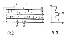
- the program control unit 14 contains a computer and controls and monitors the execution of all functions of the honing machine. In this control unit 14 all data are stored which are characteristic of the spatial assignment and the sequence of movements of the honing tool to the workpiece 2 to be machined. In addition, data are stored in the program control unit 14, with which the design of the bore wall, which results from the development of the wall surface according to FIG. 2, is recorded. In the out exemplary embodiment has the workpiece 2, ie the two-stroke cylinder to be honed, overflow channels and inlet and outlet channels 5, so that the bore wall 4 to be honed is interrupted at several points, as shown in FIG. 2.
- n 8.
- all height sections 35 receive a value number which corresponds to a fraction of the value 1 corresponding to the respective existing area of the height section; the values given in the exemplary embodiment are entered on the dividing lines 34 in FIG. 2 on the right.
- the residual area remaining after deduction of the interruption in the third height section 0.5, which means that the surface of the bore wall 4 is reduced by 50% within this height section.
- the values determined in this way for the respective surface proportion are stored in the program control unit 14 with assignment to the corresponding height sections.
- the size of the respectively machined area of the bore wall 4 is calculated using a data program which is characteristic of the tool and the workpiece and which characterize the stroke position of the tool measured by the travel sensor 10 and which is programmed in the program control unit. Unit 14 are stored.
- the calculation result is evaluated directly to control the pressure force with which the honing stones 15 are pressed against the bore wall 14.
- the pressure Force can be controlled so that the surface pressure of the honing stones 15 remains constant.
- the setpoint value of the pressure that the piston 17 must exert via the piston rod 17a as the feed pressure on the feed cone 18 is determined in the feed control device 30 on the basis of the calculation result in order to generate the predetermined radial pressure force.
- This setpoint value is compared in the delivery control unit 30 with the actual value, which is determined via the two pressure sensors 26 and 27 as the differential pressure between the two pressure chambers 19 and 21. If the actual value deviates from the target value, the delivery control device 30 delivers a signal via the control line 33 to the control valve 25 of the hydraulic control unit 23, which then adjusts the pressure in the cylinder of the delivery device 16 to the target value via the hydraulic lines 20 and 22.
- FIG. 3 shows the values of the regulated differential pressure of the chambers 19 and 21 for the path S of a working stroke above the pressure P, a step-shaped pressure curve 36 corresponding to the values for the height sections 35 (FIG. 2).
- the data which are characteristic and stored for the development of the bore wall thus lead to changes in the pressure profile 36, each height section 35 influencing the infeed pressure in accordance with the proportion of the area of the bore wall.
- With a small area share, for example in the second and third height section 35 there is a smaller contact area of the honing stones with the bore wall, and accordingly the feed pressure and thus the contact pressure is reduced via the control so that the surface pressure remains constant.
- the same effect is obtained at the end of the hole when the honing stones overflow, which in some cases extends out of the hole there ren, because then the size of the contact surface between the honing stones and the bore wall is reduced.
- the surface pressure can be increased or decreased in certain stroke positions during a working stroke in order to adapt the machining to these conditions.
- a change in the surface pressure can be entered by program control in order to achieve a specific bore shape.
- the control of the pressure force and thus the surface pressure can also be used for dimensional control.
- the measuring device 28 is provided, with which the position of the piston 17 in the cylinder of the feed device 16 is determined and input to the feed control device 30 as a signal. Since the position of the piston 17 also represents a measure of the spreading position of the honing stones 15 and thus also a measure of the width of the bore 3, the bore diameter achieved in each case can be determined in this way and the corresponding signal can be used to process after it has been reached to finish the target dimension. This size control can also be used to achieve a higher dimensional accuracy and surface quality of the hole.
- the measuring device 28 indicates to the delivery control device 30 that a bore dimension has been reached which is only slightly below the predetermined finished dimension, the pressure force and thus the surface pressure for the finish machining can be reduced, which affects the quality of the workpiece with regard to dimensional accuracy and Surface quality has a favorable effect.
Landscapes
- Engineering & Computer Science (AREA)
- Mechanical Engineering (AREA)
- Human Computer Interaction (AREA)
- Manufacturing & Machinery (AREA)
- Physics & Mathematics (AREA)
- General Physics & Mathematics (AREA)
- Automation & Control Theory (AREA)
- Finish Polishing, Edge Sharpening, And Grinding By Specific Grinding Devices (AREA)
Priority Applications (3)
| Application Number | Priority Date | Filing Date | Title |
|---|---|---|---|
| EP89105759A EP0390938A1 (fr) | 1989-04-01 | 1989-04-01 | Procédé et dispositif pour le rodage d'alésages |
| US07/496,263 US5095662A (en) | 1989-04-01 | 1990-03-20 | Process for honing bores and a honing machine for performing the process |
| JP2084782A JPH03111168A (ja) | 1989-04-01 | 1990-03-30 | 穴をホーニングする方法及びこの方法を実施するためのホーニング機械 |
Applications Claiming Priority (1)
| Application Number | Priority Date | Filing Date | Title |
|---|---|---|---|
| EP89105759A EP0390938A1 (fr) | 1989-04-01 | 1989-04-01 | Procédé et dispositif pour le rodage d'alésages |
Publications (1)
| Publication Number | Publication Date |
|---|---|
| EP0390938A1 true EP0390938A1 (fr) | 1990-10-10 |
Family
ID=8201165
Family Applications (1)
| Application Number | Title | Priority Date | Filing Date |
|---|---|---|---|
| EP89105759A Withdrawn EP0390938A1 (fr) | 1989-04-01 | 1989-04-01 | Procédé et dispositif pour le rodage d'alésages |
Country Status (3)
| Country | Link |
|---|---|
| US (1) | US5095662A (fr) |
| EP (1) | EP0390938A1 (fr) |
| JP (1) | JPH03111168A (fr) |
Cited By (7)
| Publication number | Priority date | Publication date | Assignee | Title |
|---|---|---|---|---|
| EP0499653A1 (fr) * | 1991-02-16 | 1992-08-26 | Maschinenfabrik Gehring GmbH & Co. | Machine, en particulier de rodage, pour l'usinage contrôlé par commande de mesure de pièces |
| DE4114423A1 (de) * | 1991-05-03 | 1992-11-05 | Kloeckner Humboldt Deutz Ag | Verfahren und vorrichtung zur steuerung und regelung des fertigungsprozesses beim honen von zylindern |
| DE4302475A1 (de) * | 1993-01-29 | 1994-08-04 | Nagel Masch Werkzeug | Verfahren zum Honen von Oberflächen |
| DE19606145A1 (de) * | 1996-02-20 | 1997-08-21 | Nagel Masch Werkzeug | Vorrichtung zur Aufweitung eines Honwerkzeugs |
| EP1321229A1 (fr) * | 2001-12-20 | 2003-06-25 | Maschinenfabrik Gehring GmbH & Co. | Procédé pour l'usinage d'une forure et machine de rodage pour le mettre en oeuvre |
| DE10237233A1 (de) * | 2002-08-14 | 2004-03-04 | Daimlerchrysler Ag | Spanneinrichtung einer Feinbearbeitungsvorrichtung und Verfahren zum verformungsangepassten Feinbearbeiten eines Werkstücks unter Einsatz der Spanneinrichtung |
| WO2011101243A1 (fr) * | 2010-02-17 | 2011-08-25 | Mag Ias Gmbh | Machine-outil et procédé pour l'usinage d'une pièce |
Families Citing this family (21)
| Publication number | Priority date | Publication date | Assignee | Title |
|---|---|---|---|---|
| US5293717A (en) * | 1992-07-28 | 1994-03-15 | United Technologies Corporation | Method for removal of abradable material from gas turbine engine airseals |
| US5331775A (en) * | 1992-09-08 | 1994-07-26 | Jason, Inc. | Honing process with rough honing tool and finish honing tool on same rotating head |
| CN2150970Y (zh) * | 1993-02-08 | 1993-12-29 | 许显华 | 内孔花键组合磨床 |
| US5634842A (en) * | 1995-11-08 | 1997-06-03 | Ernst Thielenhaus Kg | Apparatus for the precision grinding of conical seats for cylindrical nozzle workpieces |
| KR100526855B1 (ko) * | 1998-01-22 | 2005-11-08 | 닛다 가부시키가이샤 | 그라인더 가압장치 |
| US6095907A (en) * | 1998-10-02 | 2000-08-01 | Kennametal Inc. | Reciprocating assembly for abrading a workpiece |
| US6973367B2 (en) * | 2001-12-20 | 2005-12-06 | Maschinenfabrik Gehring Gmbh & Co. Kg | Method for producing a bore |
| DE10225514B4 (de) * | 2002-06-10 | 2005-02-17 | Kadia Produktion Gmbh + Co. | Maschine zur Feinstbearbeitung von Werkstücken durch Honen oder Feinstschleifen |
| DE10306864B3 (de) * | 2003-02-19 | 2004-07-01 | Daimlerchrysler Ag | Verfahren zur Feinbearbeitung einer zylindrischen Innenflächen |
| US8277280B2 (en) * | 2004-09-07 | 2012-10-02 | Sunnen Products Company | Honing feed system and method employing rapid tool advancement and feed force signal conditioning |
| WO2006029180A1 (fr) * | 2004-09-07 | 2006-03-16 | Sunnen Products Company | Systeme d'alimentation pour une machine a roder les cylindres disposant d'un controle complet de la force, de la vitesse et de la position d'avance et procede correspondant |
| JP5260139B2 (ja) * | 2008-05-22 | 2013-08-14 | 株式会社日進製作所 | 砥石接触感知方法およびその装置、ならびにホーニング加工方法およびホーニング盤 |
| CN101524828B (zh) * | 2009-04-03 | 2010-12-08 | 宁夏银川大河数控机床有限公司 | 复合式数控珩磨机双进给机构 |
| PL2432612T3 (pl) * | 2009-05-22 | 2017-07-31 | Sunnen Products Company | Zautomatyzowany proces wykańczania otworów |
| GB0915639D0 (en) * | 2009-09-08 | 2009-10-07 | Pipeline Tech Ltd | Method and apparatus for machining a bore |
| JP5617070B2 (ja) * | 2010-04-30 | 2014-11-05 | 株式会社竹沢精機 | 精密加工装置 |
| DE102011079900A1 (de) * | 2011-07-27 | 2013-01-31 | Grob-Werke Gmbh & Co. Kg | Verfahren und Bearbeitungsanlage zum Feinbearbeiten einer Kurbelwellenlagerbohrung |
| EP3188865B1 (fr) * | 2014-09-04 | 2020-11-18 | Sunnen Products Company | Élément de sollicitation élastique et agencement de codeur pour commande précise de force ou de couple |
| AT517140B1 (de) * | 2015-04-20 | 2017-02-15 | Tyrolit - Schleifmittelwerke Swarovski K G | Schleifwerkzeug |
| CN105081951B (zh) * | 2015-09-08 | 2018-11-30 | 重庆维庆液压机械有限公司 | 立式珩磨机标尺结构 |
| CN117773760A (zh) * | 2024-01-09 | 2024-03-29 | 北京航空航天大学宁波创新研究院 | 一种珩磨工具系统 |
Citations (5)
| Publication number | Priority date | Publication date | Assignee | Title |
|---|---|---|---|---|
| US3451175A (en) * | 1966-02-09 | 1969-06-24 | Joseph Sunnen | Honing machines |
| FR2094234A5 (fr) * | 1970-06-15 | 1972-02-04 | Buehler Ag Geb | |
| DE3042755A1 (de) * | 1980-11-13 | 1982-05-19 | Peter 7442 Neuffen Nagel | Verfahren und vorrichtung zur bearbeitung von werkstuecken mit mehreren bearbeitungsstationen |
| EP0183021A1 (fr) * | 1984-11-07 | 1986-06-04 | Waldemar Link (GmbH & Co.) | Attelle pour maintenir l'articulation extrême d'un doigt en extension |
| FR2620958A1 (fr) * | 1987-09-25 | 1989-03-31 | Sunnen Products Co | Moyen de commande pour etablir, mettre au point et controler des conditions de fonctionnement d'une machine-outil, en particulier d'une machine de honage |
Family Cites Families (2)
| Publication number | Priority date | Publication date | Assignee | Title |
|---|---|---|---|---|
| DE3039467A1 (de) * | 1980-10-18 | 1982-06-03 | Maschinenfabrik Gehring Gmbh & Co Kg, 7302 Ostfildern | Honmaschine zum bearbeiten von werkstueckbohrungen, insbesondere von sacklochbohrungen und verfahren zum betrieb der honmaschine |
| DE3600364A1 (de) * | 1986-01-09 | 1987-07-16 | Rexroth Mannesmann Gmbh | Verfahren und vorrichtung zum ausgleich des auf einen hydraulischen antrieb wirkenden veraenderlichen gewichtes einer masse, insbesondere fuer den senkrecht stehenden antriebszylinder einer laeppmaschine |
-
1989
- 1989-04-01 EP EP89105759A patent/EP0390938A1/fr not_active Withdrawn
-
1990
- 1990-03-20 US US07/496,263 patent/US5095662A/en not_active Expired - Fee Related
- 1990-03-30 JP JP2084782A patent/JPH03111168A/ja active Pending
Patent Citations (5)
| Publication number | Priority date | Publication date | Assignee | Title |
|---|---|---|---|---|
| US3451175A (en) * | 1966-02-09 | 1969-06-24 | Joseph Sunnen | Honing machines |
| FR2094234A5 (fr) * | 1970-06-15 | 1972-02-04 | Buehler Ag Geb | |
| DE3042755A1 (de) * | 1980-11-13 | 1982-05-19 | Peter 7442 Neuffen Nagel | Verfahren und vorrichtung zur bearbeitung von werkstuecken mit mehreren bearbeitungsstationen |
| EP0183021A1 (fr) * | 1984-11-07 | 1986-06-04 | Waldemar Link (GmbH & Co.) | Attelle pour maintenir l'articulation extrême d'un doigt en extension |
| FR2620958A1 (fr) * | 1987-09-25 | 1989-03-31 | Sunnen Products Co | Moyen de commande pour etablir, mettre au point et controler des conditions de fonctionnement d'une machine-outil, en particulier d'une machine de honage |
Cited By (9)
| Publication number | Priority date | Publication date | Assignee | Title |
|---|---|---|---|---|
| EP0499653A1 (fr) * | 1991-02-16 | 1992-08-26 | Maschinenfabrik Gehring GmbH & Co. | Machine, en particulier de rodage, pour l'usinage contrôlé par commande de mesure de pièces |
| DE4114423A1 (de) * | 1991-05-03 | 1992-11-05 | Kloeckner Humboldt Deutz Ag | Verfahren und vorrichtung zur steuerung und regelung des fertigungsprozesses beim honen von zylindern |
| DE4302475A1 (de) * | 1993-01-29 | 1994-08-04 | Nagel Masch Werkzeug | Verfahren zum Honen von Oberflächen |
| DE19606145A1 (de) * | 1996-02-20 | 1997-08-21 | Nagel Masch Werkzeug | Vorrichtung zur Aufweitung eines Honwerkzeugs |
| DE19606145B4 (de) * | 1996-02-20 | 2004-10-28 | Nagel Maschinen- Und Werkzeugfabrik Gmbh | Vorrichtung zur Aufweitung eines Honwerkzeugs |
| EP1321229A1 (fr) * | 2001-12-20 | 2003-06-25 | Maschinenfabrik Gehring GmbH & Co. | Procédé pour l'usinage d'une forure et machine de rodage pour le mettre en oeuvre |
| DE10237233A1 (de) * | 2002-08-14 | 2004-03-04 | Daimlerchrysler Ag | Spanneinrichtung einer Feinbearbeitungsvorrichtung und Verfahren zum verformungsangepassten Feinbearbeiten eines Werkstücks unter Einsatz der Spanneinrichtung |
| DE10237233B4 (de) * | 2002-08-14 | 2006-07-13 | Daimlerchrysler Ag | Spanneinrichtung einer Feinbearbeitungsvorrichtung und Verfahren zum verformungsangepassten Feinbearbeiten eines Werkstücks unter Einsatz der Spanneinrichtung |
| WO2011101243A1 (fr) * | 2010-02-17 | 2011-08-25 | Mag Ias Gmbh | Machine-outil et procédé pour l'usinage d'une pièce |
Also Published As
| Publication number | Publication date |
|---|---|
| JPH03111168A (ja) | 1991-05-10 |
| US5095662A (en) | 1992-03-17 |
Similar Documents
| Publication | Publication Date | Title |
|---|---|---|
| EP0390938A1 (fr) | Procédé et dispositif pour le rodage d'alésages | |
| DE69901004T2 (de) | Verfahren und vorrichtung zur bearbeitung von vorbearbeiteten, verzahnten werkstücken wie zahnräder | |
| EP0527192B1 (fr) | Procede de commande des mouvements de la molette d'une machine de fluotournage et machine de fluotournage pour mettre en oeuvre ce procede | |
| DE2758275C2 (de) | Verfahren bzw. Einrichtung zum Außenrund- und Planschleifen | |
| DE3039467A1 (de) | Honmaschine zum bearbeiten von werkstueckbohrungen, insbesondere von sacklochbohrungen und verfahren zum betrieb der honmaschine | |
| DE4036283C2 (de) | Verfahren und Vorrichtung zur Steuerung von Zylinderschleifmaschinen | |
| DE2505852C3 (de) | Schleifmaschine zum Einstechschleifen eines zylindrischen Werkstückabschnittes | |
| EP0045380A2 (fr) | Circuit de commande pour un dispositif de réglage et de dressage d'une meule | |
| DE2711862C2 (fr) | ||
| DE2537630C2 (de) | Adaptive Steuerung für eine Schleifmaschine | |
| DE3634409A1 (de) | Vorrichtung zum bearbeiten von werkstuecken durch magnetabrasives schleifen | |
| DE2030851A1 (de) | Schleifmaschine | |
| DE2047927A1 (de) | Digitalgesteuerte Schleifmaschine | |
| EP0282776B1 (fr) | Procédé d'honage | |
| CH631913A5 (de) | Einrichtung zum steuern der zustellung einer schleifscheibe relativ zu einer abrichtvorrichtung. | |
| EP0761357A2 (fr) | Procédé pour le rasage ou le honage des roues dentées cylindriques, en particulier des roues dentées ayant des flancs de dent modifiés, et procédé pour le profilage des outils de honage de roues dentées | |
| DE2645426A1 (de) | Einrichtung zur massgesteuerten bearbeitung von werkstuecken auf honmaschinen | |
| EP0549821B1 (fr) | Procédé pour opérer le pierrage de forages et tête de pierrage pour la mise en oeuvre du procédé | |
| DE10142739B4 (de) | Maschine zum Hinterarbeiten eines um eine Drehachse rotierenden Werkstücks | |
| WO1989005711A1 (fr) | Procede de taillage de meules | |
| EP0575657B2 (fr) | Méthode et machine pour l'usinage au fouesse du perçages dans des pièces à usiner | |
| DE3838751C2 (fr) | ||
| DE3817784C2 (fr) | ||
| DE1927044A1 (de) | Schleifmaschine | |
| DE2703214C2 (de) | Steuerungsvorrichtung für die Vorschubbewegungen eines Werkzeugschlittens an Werkzeugmaschinen, insbesondere für den Tiefenvorschub an Wälzfräsmaschinen |
Legal Events
| Date | Code | Title | Description |
|---|---|---|---|
| PUAI | Public reference made under article 153(3) epc to a published international application that has entered the european phase |
Free format text: ORIGINAL CODE: 0009012 |
|
| 17P | Request for examination filed |
Effective date: 19900307 |
|
| AK | Designated contracting states |
Kind code of ref document: A1 Designated state(s): AT BE CH DE ES FR GB IT LI NL SE |
|
| 17Q | First examination report despatched |
Effective date: 19920629 |
|
| STAA | Information on the status of an ep patent application or granted ep patent |
Free format text: STATUS: THE APPLICATION HAS BEEN WITHDRAWN |
|
| 18W | Application withdrawn |
Withdrawal date: 19930513 |