EP0045400A1 - Installation pour le laminage direct d'acier à grande vitesse - Google Patents
Installation pour le laminage direct d'acier à grande vitesse Download PDFInfo
- Publication number
- EP0045400A1 EP0045400A1 EP81105410A EP81105410A EP0045400A1 EP 0045400 A1 EP0045400 A1 EP 0045400A1 EP 81105410 A EP81105410 A EP 81105410A EP 81105410 A EP81105410 A EP 81105410A EP 0045400 A1 EP0045400 A1 EP 0045400A1
- Authority
- EP
- European Patent Office
- Prior art keywords
- casting
- rolling
- roughing
- strand
- section
- Prior art date
- Legal status (The legal status is an assumption and is not a legal conclusion. Google has not performed a legal analysis and makes no representation as to the accuracy of the status listed.)
- Granted
Links
- 229910000831 Steel Inorganic materials 0.000 title claims abstract description 14
- 239000010959 steel Substances 0.000 title claims abstract description 14
- 238000009434 installation Methods 0.000 title abstract description 5
- 238000005266 casting Methods 0.000 claims abstract description 99
- 238000005096 rolling process Methods 0.000 claims abstract description 54
- 238000001816 cooling Methods 0.000 claims abstract description 13
- 238000000034 method Methods 0.000 claims description 14
- 238000004519 manufacturing process Methods 0.000 claims description 6
- 239000002184 metal Substances 0.000 claims description 6
- 229910052751 metal Inorganic materials 0.000 claims description 6
- 238000004804 winding Methods 0.000 claims description 4
- 150000002739 metals Chemical class 0.000 claims description 3
- 238000005520 cutting process Methods 0.000 claims description 2
- 238000011144 upstream manufacturing Methods 0.000 claims 1
- 238000006073 displacement reaction Methods 0.000 description 3
- 238000007711 solidification Methods 0.000 description 3
- 230000008023 solidification Effects 0.000 description 3
- 238000010276 construction Methods 0.000 description 2
- -1 ferrous metals Chemical class 0.000 description 2
- 239000007788 liquid Substances 0.000 description 2
- XLYOFNOQVPJJNP-UHFFFAOYSA-N water Substances O XLYOFNOQVPJJNP-UHFFFAOYSA-N 0.000 description 2
- CWYNVVGOOAEACU-UHFFFAOYSA-N Fe2+ Chemical compound [Fe+2] CWYNVVGOOAEACU-UHFFFAOYSA-N 0.000 description 1
- 239000000463 material Substances 0.000 description 1
- 238000003303 reheating Methods 0.000 description 1
- 239000007858 starting material Substances 0.000 description 1
Images

Classifications
-
- B—PERFORMING OPERATIONS; TRANSPORTING
- B21—MECHANICAL METAL-WORKING WITHOUT ESSENTIALLY REMOVING MATERIAL; PUNCHING METAL
- B21B—ROLLING OF METAL
- B21B1/00—Metal-rolling methods or mills for making semi-finished products of solid or profiled cross-section; Sequence of operations in milling trains; Layout of rolling-mill plant, e.g. grouping of stands; Succession of passes or of sectional pass alternations
- B21B1/46—Metal-rolling methods or mills for making semi-finished products of solid or profiled cross-section; Sequence of operations in milling trains; Layout of rolling-mill plant, e.g. grouping of stands; Succession of passes or of sectional pass alternations for rolling metal immediately subsequent to continuous casting
- B21B1/466—Metal-rolling methods or mills for making semi-finished products of solid or profiled cross-section; Sequence of operations in milling trains; Layout of rolling-mill plant, e.g. grouping of stands; Succession of passes or of sectional pass alternations for rolling metal immediately subsequent to continuous casting in a non-continuous process, i.e. the cast being cut before rolling
-
- B—PERFORMING OPERATIONS; TRANSPORTING
- B21—MECHANICAL METAL-WORKING WITHOUT ESSENTIALLY REMOVING MATERIAL; PUNCHING METAL
- B21B—ROLLING OF METAL
- B21B1/00—Metal-rolling methods or mills for making semi-finished products of solid or profiled cross-section; Sequence of operations in milling trains; Layout of rolling-mill plant, e.g. grouping of stands; Succession of passes or of sectional pass alternations
- B21B1/16—Metal-rolling methods or mills for making semi-finished products of solid or profiled cross-section; Sequence of operations in milling trains; Layout of rolling-mill plant, e.g. grouping of stands; Succession of passes or of sectional pass alternations for rolling wire rods, bars, merchant bars, rounds wire or material of like small cross-section
- B21B1/18—Metal-rolling methods or mills for making semi-finished products of solid or profiled cross-section; Sequence of operations in milling trains; Layout of rolling-mill plant, e.g. grouping of stands; Succession of passes or of sectional pass alternations for rolling wire rods, bars, merchant bars, rounds wire or material of like small cross-section in a continuous process
-
- B—PERFORMING OPERATIONS; TRANSPORTING
- B21—MECHANICAL METAL-WORKING WITHOUT ESSENTIALLY REMOVING MATERIAL; PUNCHING METAL
- B21B—ROLLING OF METAL
- B21B31/00—Rolling stand structures; Mounting, adjusting, or interchanging rolls, roll mountings, or stand frames
- B21B31/02—Rolling stand frames or housings; Roll mountings ; Roll chocks
- B21B2031/026—Transverse shifting the stand
Definitions
- the invention relates to a method and a plant for the casting-rolling of metals, in particular steel, at high speeds, at which the continuously produced casting strand completely solidifies and, after passing through a temperature compensation section, is fed to a roughing mill and subsequently interposed and in several rolling mills is finish-rolled before being subjected to further treatment processes in the form of a rod or wire.
- Casting and rolling systems for steel for casting relatively large casting cross sections have also become known, which have a roughing mill arranged directly behind the secondary cooling section of the casting machine. This arrangement was intended to shorten the solidification length and to distribute and close non-metallic inclusions and cavities in the cast strand more evenly.
- the excessive deformation of the liquid strand core during the pre-rolling caused such high stresses that cracks formed in the strand core which prevented further deformation.
- the invention has for its object to provide a method and a system for casting rolling, in particular steel, which allow a high output with relatively low investment costs.
- the method and the system should also be designed so that the particularly high Casting speeds required space is reduced.
- the idea of the solution on which the invention is based then consists in equipping the casting and rolling plant with two mutually independent complete casting sections, to which a single roughing mill movable transversely to the casting direction is optionally assigned.
- the second casting line is put into operation in the event of failure of the other casting line, so that the downstream rolling mill can continue to work with a short interruption.
- the displaceable arrangement of the roughing mill has the advantage that the casting strand can be introduced into the mill stands of the roughing mill without being deflected.
- each casting section can additionally be equipped with a drive unit; this is located behind the temperature compensation section, advantageously in the area between the latter and the subsequent shear.
- the plant according to the invention is further designed in such a way that a 180 o- deflection unit is arranged in the region between the roughing mill and the rolling treatment final finishing train, which determines the direction of movement of the cast strand during the further treatment processes.
- the 180 ° deflection unit is in any case arranged in an area behind the roughing mill, that is to say in an area in which the cross section of the pre-rolled casting strand has no particular difficulties with. the deformation associated with the deflection.
- the length of the casting and rolling system may be reduced by up to 50%; This not only leads to a reduction in the length of the hall, but also to a reduction in the installation costs for the oil, water, air, hydraulic and electrical supply to the casting and rolling system.
- the 180 ° deflection unit is at most behind the second intermediate street (claim 3); Depending on the operating conditions, it can also be expedient to arrange the 180 ° deflection unit between the two intermediate streets.
- the rolling stands of the roughing mill can be moved with respect to their fixed rolling drive (claim 5).
- the rolling stands of the roughing mill are each arranged on their own sliding frame and connected to their rolling drive via cardan shafts (claim 6).
- the casting and rolling plant is to be used for wire production, it preferably also has the features of claim 7 and / or claim 8.
- the process for casting metal rolling is essentially characterized in that it has the characteristics of Claims 9 and / or 10.
- the method can furthermore be designed such that the casting strand - which is optionally produced from different casting sections - reaches its effective area by moving the roll stands of the roughing train transversely to the casting direction.
- the casting lines 1 and 1a which are preferably constructed in this way, are followed by a single roughing line 7 common to both casting lines, which in the exemplary embodiment shown is composed of three roll stands 8, 9 and 10.
- the roughing mill 7 can be moved transversely to the casting direction (arrow 11) such that it lies either in the region of the longitudinal axis 12 of the casting section 1 or in the region of the longitudinal axis 12a of the casting section 1a.
- the two above-mentioned operating positions, in which the preliminary road 7 is assigned to the casting line 1 or the casting line 1a are denoted in the drawing with solid lines or with dash-dotted lines; the transverse displaceability of the Vorée 7 is to be indicated by a double arrow 13.
- the use of two mutually independent casting sections 1 and 1a is intended to ensure that the production of the casting and rolling system can be maintained in the event of a casting section failure, in particular a casting machine.
- the casting machines 2 and 2a are designed in a manner known per se; they can in particular consist of two casting belts delimiting a casting cross section or of a casting wheel which interacts with a suitably designed casting belt.
- the liquid steel to be processed is cast into a casting strand in one of the two casting machines - for example in the casting machine 2 - and there it receives an approximately 10 to 20 mm thick shell.
- the casting strand solidifies under the influence of an intensive one Water cooling completely through, in the temperature compensation section 4, the temperature gradient between the strand shell and the strand core is reduced and, if necessary, the casting strand back to rolling temperature. temperature is heated.
- the two casting lines 1 and 1a are connected by the rolling mill, which consists of the aforementioned roughing mill 7, a first intermediate mill 14, a 180 ° deflection unit 15, a second intermediate mill 16, a finishing mill 17, a primary cooling section 18, a winding layer 19, one Secondary cooling section 20 and a collecting station 21.
- the casting strand pre-rolled in the roughing mill 7 and reduced to a suitable cross-section is further deformed in the intermediate streets 14 and 16 before it receives the desired wire cross-section when passing through the finishing train 17.
- the deflection unit 180 0- 15 In the area between the roughing train and the finishing train 17 7 - in the illustrated embodiment, between the two intermediate trains 14 and 16 - passes through the cast strand, the deflection unit 180 0- 15; he thereby receives a movement direction 22 opposite to the casting direction 11, which remains during the subsequent treatment processes.
- the casting strand runs, for example in wire form, through the primary cooling section 18 of the rolling mill, is turned into turns by means of the winding layer 19 and is guided over the secondary cooling section 20 of the rolling mill before it is collected into wire rings in the collecting station 21.
- the deflection of the casting strand - which, depending on the cross section, can be carried out before, between and after the two intermediate streets 14 and 16 - leads to one Significant reduction in space requirements and installation costs for the supply equipment of the casting and rolling plant.
- the displaceable arrangement of the roughing road 7 makes deflection of the casting strand, which still has the full casting cross section in this area, superfluous.
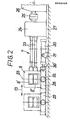
- the roll stand 8 of the roughing mill lying in front in the casting direction is an example. 7, which can be moved back and forth in the direction of the double arrow 13.
- the schematically represented rollers 8 ′ and 8 ′′ are connected to a gear 24 by means of cardan shafts 23 and, with the interposition of a clutch 25, to a motor 26 serving as a roller drive arranged.
- the roll stand 8 (like the other roll stands 9 and 10 of the roughing mill 7, not shown) is movably held on a sliding frame 28 within a fixed guide 29.
- the displacement frame 28 is connected in an articulated manner to the piston rod 30 'of a cylinder unit 30, which serves as a displacement drive and in turn is held in a stationary manner via a bracket 31.
- the sliding frame 28 of the roll stand 8 is equipped with a clamping device 32 which clamps it in the selected operating position with the guide 29 and thus holds it in place.
- the roll stand 8 (and the subsequent roll stands of the roughing mill) assume a position in which the roll center 33 coincides with the longitudinal axis 12 indicated in FIG. 1 falls; the second operating position of the roll stand 8 is indicated by dash-dotted lines in FIG. 1.
- the stationary arrangement of the roller drive and the displacement drive with respect to the roll stands has the advantage that the installation of these drives is simplified and the size of the masses to be moved is kept as small as possible.
- the casting and rolling system and possibly the 180 0 deflection unit can - in contrast to the application example shown in FIG. 1 (downstream rolling mill line) also interact with a rolling mill for the production of fine steel.
Landscapes
- Engineering & Computer Science (AREA)
- Mechanical Engineering (AREA)
- Metal Rolling (AREA)
- Manufacture Of Alloys Or Alloy Compounds (AREA)
- Heat Treatment Of Steel (AREA)
- Laminated Bodies (AREA)
- Forging (AREA)
- Extrusion Of Metal (AREA)
Priority Applications (1)
| Application Number | Priority Date | Filing Date | Title |
|---|---|---|---|
| AT81105410T ATE8215T1 (de) | 1980-08-01 | 1981-07-11 | Anlage zum giesswalzen von stahl mit hohen geschwindigkeiten. |
Applications Claiming Priority (2)
| Application Number | Priority Date | Filing Date | Title |
|---|---|---|---|
| DE19803029222 DE3029222A1 (de) | 1980-08-01 | 1980-08-01 | Verfahren und anlage zum giesswalzen von metallen, insbesondere von stahl, mit hohen geschwindigkeiten |
| DE3029222 | 1980-08-01 |
Publications (2)
| Publication Number | Publication Date |
|---|---|
| EP0045400A1 true EP0045400A1 (fr) | 1982-02-10 |
| EP0045400B1 EP0045400B1 (fr) | 1984-07-04 |
Family
ID=6108678
Family Applications (1)
| Application Number | Title | Priority Date | Filing Date |
|---|---|---|---|
| EP81105410A Expired EP0045400B1 (fr) | 1980-08-01 | 1981-07-11 | Installation pour le laminage direct d'acier à grande vitesse |
Country Status (8)
| Country | Link |
|---|---|
| EP (1) | EP0045400B1 (fr) |
| JP (1) | JPS5752505A (fr) |
| AT (1) | ATE8215T1 (fr) |
| AU (1) | AU542054B2 (fr) |
| BR (1) | BR8104981A (fr) |
| CA (1) | CA1169225A (fr) |
| DE (1) | DE3029222A1 (fr) |
| NO (1) | NO812477L (fr) |
Cited By (5)
| Publication number | Priority date | Publication date | Assignee | Title |
|---|---|---|---|---|
| EP0492226A3 (en) * | 1990-12-21 | 1992-08-26 | Sms Schloemann-Siemag Aktiengesellschaft | Method of and installation for rolling hot wide strip starting from continuous cast thin slab |
| EP0593002A1 (fr) * | 1992-10-13 | 1994-04-20 | Sms Schloemann-Siemag Aktiengesellschaft | Méthode et dispositif pour laminage de bandes larges à brames minces en coulée continue |
| WO2005002749A3 (fr) * | 2003-07-03 | 2005-03-31 | Sms Demag Ag | Dispositif pour la production de feuillard d'acier lamine a chaud, en particulier a partir d'ebauche en bande coulee en continu |
| AT513298B1 (de) * | 2012-08-20 | 2017-03-15 | Primetals Technologies Austria GmbH | Zwischenstraßenbereich einer Gieß-Walz-Verbundanlage |
| CN110180899A (zh) * | 2019-06-13 | 2019-08-30 | 中冶赛迪工程技术股份有限公司 | 一种用于高速铸轧机的开式牌坊及组合 |
Citations (4)
| Publication number | Priority date | Publication date | Assignee | Title |
|---|---|---|---|---|
| DE1527706A1 (de) * | 1966-01-19 | 1970-01-22 | Schloemann Ag | Vorrichtung zum Verschieben von Walzgeruesten bzw. der Walzensaetze von Walzgeruesten quer zur Walzrichtung |
| AT297640B (de) * | 1969-04-23 | 1972-04-10 | Voest Ag | Walzgerüst und Walzwerksanlage, insbesondere für die Verformung eines direkt aus einer Stranggußanlage auslaufenden Gußstranges |
| US3786664A (en) * | 1972-03-20 | 1974-01-22 | Steel Corp | Rolling mill module |
| DE2418853A1 (de) * | 1973-06-25 | 1975-01-16 | Morgan Construction Co | Verfahren und vorrichtung zum kontinuierlichen giessen und walzen eines products aus nichteisenmetall |
Family Cites Families (2)
| Publication number | Priority date | Publication date | Assignee | Title |
|---|---|---|---|---|
| JPS5545530A (en) * | 1978-09-25 | 1980-03-31 | Chiyoda Koutetsu Kogyo Kk | Direct rolling equipment for continuous casting having moving type continuous heating furnaces |
| JPS55147405A (en) * | 1979-05-04 | 1980-11-17 | Nippon Steel Corp | Rolling mill |
-
1980
- 1980-08-01 DE DE19803029222 patent/DE3029222A1/de not_active Withdrawn
-
1981
- 1981-07-09 AU AU72698/81A patent/AU542054B2/en not_active Ceased
- 1981-07-11 AT AT81105410T patent/ATE8215T1/de active
- 1981-07-11 EP EP81105410A patent/EP0045400B1/fr not_active Expired
- 1981-07-20 NO NO812477A patent/NO812477L/no unknown
- 1981-07-31 BR BR8104981A patent/BR8104981A/pt unknown
- 1981-07-31 CA CA000382974A patent/CA1169225A/fr not_active Expired
- 1981-07-31 JP JP56119418A patent/JPS5752505A/ja active Pending
Patent Citations (4)
| Publication number | Priority date | Publication date | Assignee | Title |
|---|---|---|---|---|
| DE1527706A1 (de) * | 1966-01-19 | 1970-01-22 | Schloemann Ag | Vorrichtung zum Verschieben von Walzgeruesten bzw. der Walzensaetze von Walzgeruesten quer zur Walzrichtung |
| AT297640B (de) * | 1969-04-23 | 1972-04-10 | Voest Ag | Walzgerüst und Walzwerksanlage, insbesondere für die Verformung eines direkt aus einer Stranggußanlage auslaufenden Gußstranges |
| US3786664A (en) * | 1972-03-20 | 1974-01-22 | Steel Corp | Rolling mill module |
| DE2418853A1 (de) * | 1973-06-25 | 1975-01-16 | Morgan Construction Co | Verfahren und vorrichtung zum kontinuierlichen giessen und walzen eines products aus nichteisenmetall |
Cited By (6)
| Publication number | Priority date | Publication date | Assignee | Title |
|---|---|---|---|---|
| EP0492226A3 (en) * | 1990-12-21 | 1992-08-26 | Sms Schloemann-Siemag Aktiengesellschaft | Method of and installation for rolling hot wide strip starting from continuous cast thin slab |
| EP0593002A1 (fr) * | 1992-10-13 | 1994-04-20 | Sms Schloemann-Siemag Aktiengesellschaft | Méthode et dispositif pour laminage de bandes larges à brames minces en coulée continue |
| WO2005002749A3 (fr) * | 2003-07-03 | 2005-03-31 | Sms Demag Ag | Dispositif pour la production de feuillard d'acier lamine a chaud, en particulier a partir d'ebauche en bande coulee en continu |
| AT513298B1 (de) * | 2012-08-20 | 2017-03-15 | Primetals Technologies Austria GmbH | Zwischenstraßenbereich einer Gieß-Walz-Verbundanlage |
| CN110180899A (zh) * | 2019-06-13 | 2019-08-30 | 中冶赛迪工程技术股份有限公司 | 一种用于高速铸轧机的开式牌坊及组合 |
| CN110180899B (zh) * | 2019-06-13 | 2024-02-23 | 中冶赛迪工程技术股份有限公司 | 一种用于高速铸轧机的开式牌坊及组合 |
Also Published As
| Publication number | Publication date |
|---|---|
| NO812477L (no) | 1982-02-02 |
| BR8104981A (pt) | 1982-04-20 |
| ATE8215T1 (de) | 1984-07-15 |
| DE3029222A1 (de) | 1982-03-04 |
| EP0045400B1 (fr) | 1984-07-04 |
| AU542054B2 (en) | 1985-02-07 |
| AU7269881A (en) | 1982-02-04 |
| CA1169225A (fr) | 1984-06-19 |
| JPS5752505A (en) | 1982-03-29 |
Similar Documents
| Publication | Publication Date | Title |
|---|---|---|
| EP0853987B1 (fr) | Installation pour la production d'un feuillard, d'un feuillard ébaucheé ou d'une bramme | |
| WO1997036699A1 (fr) | Procede et unite pour fabriquer un feuillard d'acier lamine a chaud | |
| AT506603A1 (de) | Verfahren und vorrichtung für eine giess-walz-verbundanlage | |
| EP0371281B1 (fr) | Installation pour la production de bandes d'acier laminées à chaud | |
| EP0829322B1 (fr) | Cisaille à grande vitesse pour le tronçonnage de feuillard laminé | |
| AT410767B (de) | Verfahren und vorrichtung zur kontinuierlichen herstellung eines gewalzten metallbandes aus einermetallschmelze | |
| AT408420B (de) | Anlage zur herstellung von warmgewalztem stahlband | |
| EP1414597A1 (fr) | Dispositif et procede de changement automatique des cylindres de travail, des cylindres d'appui et des cylindres intermediaires d'un laminoir a feuillards equipe d'au moins une cage de laminoir | |
| DE69712429T2 (de) | Verfahren zum Schweissen von Knüppeln die aus einem Ofen herausgenommen sind, und Walzanlage zur Anwendung dieses Verfahrens | |
| DE4009861C2 (de) | Verfahren zur Herstellung von warmgewalztem Stangenmaterial wie Feinstahl oder Draht und Anlage zur Durchführung des Verfahrens | |
| LU85485A1 (de) | Vorrichtung und verfahren zum kontinuierlichen giessen von metall | |
| EP0560093B1 (fr) | Laminoir à fers marchands et à fil d'acier | |
| DE920362C (de) | Verfahren und Anlage zur Herstellung von Metall-Halbfabrikaten ver-schiedener Art (Draehte, Barren, Stangen, Platten, Baender, Bleche od. dgl.) | |
| EP0045400A1 (fr) | Installation pour le laminage direct d'acier à grande vitesse | |
| DE3803592A1 (de) | Verfahren und anlage zum walzen von auf einer bandgiessanlage gegossenen vorbaendern | |
| DE4009860C2 (de) | Verfahren und Anlage zur Herstellung von warmgewalztem Stahlband, insbesondere für Edelstähle, aus bandförmig stranggegossenem Vormaterial | |
| DE102021209261A1 (de) | Verfahren zur Steuerung einer Walzgutführung in einer Walzstraße sowie Zwischengerüstführung | |
| DE1934302A1 (de) | Verfahren und Vorrichtung zum Warmwalzen von Metallbrammen | |
| DE2514783A1 (de) | Verfahren und vorrichtung zum walzen von metall | |
| WO2012139968A1 (fr) | Procédé et installation de coulée continue verticale permettant de produire des brames épaisses à partir d'une masse de métal fondu | |
| DE3317635A1 (de) | Warmwalzverfahren | |
| EP0560115A1 (fr) | Procédé et laminoir pour le laminage de précision de fil respectivement de produit laminé à section circulaire | |
| WO2002090019A1 (fr) | Procede et dispositif permettant la coulee continue de blocs, de brames ou de brames minces | |
| WO2022258254A1 (fr) | Gestion d'une interruption de production dans une installation combinée de coulée-laminage | |
| DE10444C (de) | Neuerungen an dem Verfahren und den Apparaten zur Herstellung verschiedener Theile von Eisenbahnweichen |
Legal Events
| Date | Code | Title | Description |
|---|---|---|---|
| PUAI | Public reference made under article 153(3) epc to a published international application that has entered the european phase |
Free format text: ORIGINAL CODE: 0009012 |
|
| AK | Designated contracting states |
Designated state(s): AT BE CH FR GB IT LU NL SE |
|
| 17P | Request for examination filed |
Effective date: 19820707 |
|
| ITF | It: translation for a ep patent filed | ||
| GRAA | (expected) grant |
Free format text: ORIGINAL CODE: 0009210 |
|
| PGFP | Annual fee paid to national office [announced via postgrant information from national office to epo] |
Ref country code: FR Payment date: 19840626 Year of fee payment: 4 |
|
| AK | Designated contracting states |
Designated state(s): AT BE CH FR GB IT LI LU NL SE |
|
| REF | Corresponds to: |
Ref document number: 8215 Country of ref document: AT Date of ref document: 19840715 Kind code of ref document: T |
|
| PG25 | Lapsed in a contracting state [announced via postgrant information from national office to epo] |
Ref country code: LU Free format text: LAPSE BECAUSE OF NON-PAYMENT OF DUE FEES Effective date: 19840731 |
|
| PGFP | Annual fee paid to national office [announced via postgrant information from national office to epo] |
Ref country code: CH Payment date: 19840828 Year of fee payment: 4 |
|
| ET | Fr: translation filed | ||
| PGFP | Annual fee paid to national office [announced via postgrant information from national office to epo] |
Ref country code: SE Payment date: 19840930 Year of fee payment: 4 Ref country code: BE Payment date: 19840930 Year of fee payment: 4 |
|
| PLBE | No opposition filed within time limit |
Free format text: ORIGINAL CODE: 0009261 |
|
| STAA | Information on the status of an ep patent application or granted ep patent |
Free format text: STATUS: NO OPPOSITION FILED WITHIN TIME LIMIT |
|
| 26N | No opposition filed | ||
| PGFP | Annual fee paid to national office [announced via postgrant information from national office to epo] |
Ref country code: AT Payment date: 19850715 Year of fee payment: 5 |
|
| PGFP | Annual fee paid to national office [announced via postgrant information from national office to epo] |
Ref country code: NL Payment date: 19850731 Year of fee payment: 5 |
|
| PG25 | Lapsed in a contracting state [announced via postgrant information from national office to epo] |
Ref country code: AT Effective date: 19860711 |
|
| PG25 | Lapsed in a contracting state [announced via postgrant information from national office to epo] |
Ref country code: SE Effective date: 19860712 |
|
| PG25 | Lapsed in a contracting state [announced via postgrant information from national office to epo] |
Ref country code: LI Effective date: 19860731 Ref country code: CH Effective date: 19860731 Ref country code: BE Effective date: 19860731 |
|
| BERE | Be: lapsed |
Owner name: FRIED. KRUPP G.M.B.H. Effective date: 19860731 |
|
| PG25 | Lapsed in a contracting state [announced via postgrant information from national office to epo] |
Ref country code: NL Effective date: 19870201 |
|
| NLV4 | Nl: lapsed or anulled due to non-payment of the annual fee | ||
| PG25 | Lapsed in a contracting state [announced via postgrant information from national office to epo] |
Ref country code: FR Free format text: LAPSE BECAUSE OF NON-PAYMENT OF DUE FEES Effective date: 19870331 |
|
| REG | Reference to a national code |
Ref country code: CH Ref legal event code: PL |
|
| GBPC | Gb: european patent ceased through non-payment of renewal fee | ||
| REG | Reference to a national code |
Ref country code: FR Ref legal event code: ST |
|
| PG25 | Lapsed in a contracting state [announced via postgrant information from national office to epo] |
Ref country code: GB Effective date: 19881118 |
|
| EUG | Se: european patent has lapsed |
Ref document number: 81105410.5 Effective date: 19870518 |