EP0045412A2 - Installation pour le contrôle de matériaux - Google Patents
Installation pour le contrôle de matériaux Download PDFInfo
- Publication number
- EP0045412A2 EP0045412A2 EP81105568A EP81105568A EP0045412A2 EP 0045412 A2 EP0045412 A2 EP 0045412A2 EP 81105568 A EP81105568 A EP 81105568A EP 81105568 A EP81105568 A EP 81105568A EP 0045412 A2 EP0045412 A2 EP 0045412A2
- Authority
- EP
- European Patent Office
- Prior art keywords
- pole
- pole piece
- windings
- eddy current
- heat
- Prior art date
- Legal status (The legal status is an assumption and is not a legal conclusion. Google has not performed a legal analysis and makes no representation as to the accuracy of the status listed.)
- Withdrawn
Links
Images


Classifications
-
- G—PHYSICS
- G01—MEASURING; TESTING
- G01N—INVESTIGATING OR ANALYSING MATERIALS BY DETERMINING THEIR CHEMICAL OR PHYSICAL PROPERTIES
- G01N29/00—Investigating or analysing materials by the use of ultrasonic, sonic or infrasonic waves; Visualisation of the interior of objects by transmitting ultrasonic or sonic waves through the object
- G01N29/22—Details, e.g. general constructional or apparatus details
- G01N29/24—Probes
- G01N29/2412—Probes using the magnetostrictive properties of the material to be examined, e.g. electromagnetic acoustic transducers [EMAT]
-
- G—PHYSICS
- G01—MEASURING; TESTING
- G01N—INVESTIGATING OR ANALYSING MATERIALS BY DETERMINING THEIR CHEMICAL OR PHYSICAL PROPERTIES
- G01N2291/00—Indexing codes associated with group G01N29/00
- G01N2291/02—Indexing codes associated with the analysed material
- G01N2291/028—Material parameters
- G01N2291/02854—Length, thickness
-
- G—PHYSICS
- G01—MEASURING; TESTING
- G01N—INVESTIGATING OR ANALYSING MATERIALS BY DETERMINING THEIR CHEMICAL OR PHYSICAL PROPERTIES
- G01N2291/00—Indexing codes associated with group G01N29/00
- G01N2291/04—Wave modes and trajectories
- G01N2291/042—Wave modes
- G01N2291/0421—Longitudinal waves
-
- G—PHYSICS
- G01—MEASURING; TESTING
- G01N—INVESTIGATING OR ANALYSING MATERIALS BY DETERMINING THEIR CHEMICAL OR PHYSICAL PROPERTIES
- G01N2291/00—Indexing codes associated with group G01N29/00
- G01N2291/04—Wave modes and trajectories
- G01N2291/042—Wave modes
- G01N2291/0422—Shear waves, transverse waves, horizontally polarised waves
Definitions
- the invention relates to a device for testing para and diamagnetic metallic materials and ferromagnetic materials above their Curie points for material defects and dimensional accuracy, in particular for testing pipes and slabs above 1000 ° C, consisting essentially of an electrodynamic converter with two magnetic pole shoes , Eddy current excitation and reception windings and an electronic evaluation unit.
- piezoelectric transducers with a high-pressure running water coupling.
- a water path is created between the test object and the ultrasonic transducer at high pressure.
- the success of the process depends strongly depends on the surface quality of the test specimen. The process is relatively slow and relatively large amounts of water are required. The local cooling of the test object through the coupling water can lead to tensions and cracks in the test object.
- Piezoelectric transducers with press couplings are also known.
- the vibrator can be directly coupled under high contact pressure in the area of a roller, but this severely limits the place of use, since measurements cannot be taken at any point on the rolling mill. A measurement for tolerance accuracy is not possible with this method.
- electrodynamic excitation of ultrasound which is based on the fact that a force is exerted on a current-carrying body in a magnetic field that acts perpendicular to the plane spanned by the magnetic field and the current vector.
- An electromagnet generates the magnetic field via a pole piece configuration, while the current is excited as an eddy current pulse via a transducer coil in the test object.
- the size of the resulting force pulse and thus the strength of the ultrasound pulse essentially depends on the eddy current strength and above all on the magnetic field strength.
- the electrodynamic transducer head In order to be able to generate both factors in the order of magnitude that permit ultrasonic evaluation, the electrodynamic transducer head must be brought very close to the test object.
- the object was achieved in that the pole pieces of the transducer are shaped such that a magnetic field parallel to the test specimen is formed and the eddy current excitation and reception windings are thermally insulated from the test specimen.
- windings are preferably embedded in a heat-insulating ceramic layer on the side facing the test object and in a heat-conductive ceramic layer on the side facing away.
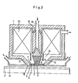
- the device consists essentially of an electrodynamic converter (1) with the excitation winding (22), the magnetic pole shoes (8, 11) and the eddy current excitation or reception windings (5, 3) and evaluation electronics (23).
- the eddy current excitation and reception windings (5, 3) are designed to be temperature-resistant because they have to be brought up to about 1 mm to the hot test object (2). Accordingly, there is a heat-insulating protective ceramic (6), for example approximately 0.5 mm thick, preferably made of aluminum oxide, on the test specimen on the windings (3, 5). Even in the extreme case of a test specimen temperature of 1 300 0 C, the temperature on the converter side does not rise above approx. 350 ° C.
- the insulated wire used for the windings (3, 5), for example copper wire, can withstand constant loads up to approx. 200 ° C.
- This second ceramic layer (7) serves as heat conduction and advantageously seals off the gaps to the pole shoes (8, 11) which are necessary for reasons of the expandability of the thermal insulation ceramic plate (6).
- a heat-conductive ceramic adhesive is preferably used for this.
- the surface of the windings (3, 5) on the converter side is advantageously additionally cooled by a cooling liquid (24).
- a suitable shape of the pole shoes (8, 11) is of great importance.
- a strong magnetic field (25) must be generated parallel to the surface of the test object.
- Only horizontal components are desired.
- Vertical components stimulate transverse waves, which, however, do not find any propagation conditions in hot test objects and lead to disturbing echoes in cold para and diamagnetic materials.
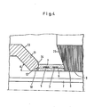
- the pole piece (8) has a conical shape.
- the angle of the cone (35) depends on the width of the eddy current excitation windings and eddy current reception windings (3, 5) required.
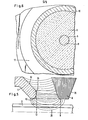
- the size of the surface (9) of one pole piece (8) parallel to the test object (2) is approximately equal to the size of the corresponding surface (10) of the counter-pole shoe (11).
- the other pole piece (11) against the plane of the pole faces (9, 10) to tilt by at least an angle of 25 0th
- the inclination of the edge surface (12) advantageously corresponds approximately to the angle of the cone surface (35) of the pole piece (8).
- the edge created by the lateral surface (13) of the pole piece (11) and the inclined surface (12) is broken and forms an edge surface (34). This avoids the magnetic fields that are otherwise particularly strong here due to the peak effect (due to the reduction in distance).
- the shape and the inclination of the pole shoes (8, 11) are also of particular importance ; for a second reason too.
- the inclination of the pole piece is so that the eddy currents induced by windings (3, 5) in the pole pieces (8, 11), which lead to ultrasound impulses in the pole pieces, repeatedly return to their original locations as interference noise can appear in the receiver (11) advantageously to be chosen so that these interference pulses on the pole shoe (11) run outwards.
- the pole piece (8) is preferably constructed from mutually insulated sheets. This also results in an expansion of the tolerance ranges for the distance between the. Probe (1) to the test object (2).
- the pole piece (11) preferably has a cooler (14) through which a coolant flows and made of non-ferritic material.
- the pole piece (8) is provided with a cooling channel (26) which also guides the coolant past the heat-conducting ceramic layer (7) and the magnetic field excitation winding (22) and thus also takes over the cooling thereof.
- the coolant is pumped through the converter head (1) in a closed or open circuit (27).
- Fig. I shows the electronic structure of the device according to the invention.
- a transmitter (28) feeds the eddy current excitation winding (5) via an adapter (29). Echoes from the test specimen (2) are received via the receive winding (3).
- the signals reach the display amplifier (30) and the display (31) via an active adaptation (4).
- the entire process is activated by a controller (32).
- the magnetic field is controlled by a direct current source (33).
- the active adapter (4) of the electronic evaluation unit preferably consists of an attenuator (16), one or more matching capacitors (17), a transmit / receive switch (18), a filter (19), a preamplifier (20) and a line driver (21) . (Fig. II)
- One or more capacitors are used as the adapter (17).
- the signals are tapped by this adapter (17), transmitted to the line via the preamplifier (20) and then via a line driver amplifier (21), the length of which can be arbitrary in this configuration.
- a transceiver switch (18) is provided, which essentially consists of an analog switch and various protective diodes.
- the electronically switchable attenuator (16) located in the input circuit has the effect that the resonant oscillator circuit, which consists of the excitation winding (3) and the adapter (17), is so damped in the case of transmission that there is no impermissibly long dead zone in which no echoes can be received . If the distance of the transducer (1) to the test object (2) changes for tolerance reasons, this means a variation of the resonant circuit damping, which leads to the transmission dead time being extended and the echo pulses being broadened. However, broadening the echo pulse would impair the resolution of the method.
- the active adapter (4) according to the invention ensures suitable attenuation of the transmit and echo signals, which is implemented by an electronically switchable attenuator (16) and a bandpass filter (19).
- the process is not limited to air as the working medium and also works under strong radiation, e.g. in hot cells of nuclear facilities.
Landscapes
- Physics & Mathematics (AREA)
- Electromagnetism (AREA)
- Health & Medical Sciences (AREA)
- Life Sciences & Earth Sciences (AREA)
- Chemical & Material Sciences (AREA)
- Analytical Chemistry (AREA)
- Biochemistry (AREA)
- General Health & Medical Sciences (AREA)
- General Physics & Mathematics (AREA)
- Immunology (AREA)
- Pathology (AREA)
- Investigating Or Analyzing Materials By The Use Of Magnetic Means (AREA)
- Investigating Or Analyzing Materials By The Use Of Ultrasonic Waves (AREA)
Applications Claiming Priority (2)
| Application Number | Priority Date | Filing Date | Title |
|---|---|---|---|
| DE19803029036 DE3029036A1 (de) | 1980-07-31 | 1980-07-31 | Vorrichtung zur pruefung von werkstoffen |
| DE3029036 | 1980-07-31 |
Publications (2)
| Publication Number | Publication Date |
|---|---|
| EP0045412A2 true EP0045412A2 (fr) | 1982-02-10 |
| EP0045412A3 EP0045412A3 (fr) | 1984-04-18 |
Family
ID=6108558
Family Applications (1)
| Application Number | Title | Priority Date | Filing Date |
|---|---|---|---|
| EP81105568A Withdrawn EP0045412A3 (fr) | 1980-07-31 | 1981-07-15 | Installation pour le contrôle de matériaux |
Country Status (5)
| Country | Link |
|---|---|
| EP (1) | EP0045412A3 (fr) |
| JP (1) | JPS5753654A (fr) |
| CA (1) | CA1186735A (fr) |
| DE (1) | DE3029036A1 (fr) |
| ZA (1) | ZA814966B (fr) |
Cited By (12)
| Publication number | Priority date | Publication date | Assignee | Title |
|---|---|---|---|---|
| EP0069865A3 (en) * | 1981-06-16 | 1984-05-30 | Nukem Gmbh | Electrodynamic movable head |
| DE3414071C1 (de) * | 1984-04-13 | 1985-04-11 | Nukem Gmbh, 6450 Hanau | Elektrodynamischer Wandler |
| GB2152668A (en) * | 1984-01-13 | 1985-08-07 | Nukem Gmbh | Electrodynamic transducer head |
| DE3425386C1 (de) * | 1984-07-10 | 1985-11-14 | Nukem Gmbh, 6450 Hanau | Elektrodynamischer Wandler |
| DE3524167A1 (de) * | 1984-07-13 | 1986-01-16 | Centro Sperimentale Metallurgico S.p.A., Rom/Roma | Sonde fuer die kontrolle von oberflaechendefekten metallischer koerper bei hohen temperaturen |
| EP0189780A1 (fr) * | 1985-01-28 | 1986-08-06 | Siemens Aktiengesellschaft | Tube éclateur à ondes de chocs à longue durée de vie |
| DE3448080A1 (de) * | 1984-04-13 | 1986-08-07 | Nukem Gmbh, 6450 Hanau | Elektrodynamischer wandler |
| FR2608765A1 (fr) * | 1986-03-19 | 1988-06-24 | Unimetal Sa | Sonde de detection de defauts de profils metalliques a temperature elevee par courants de foucault |
| DE3935432A1 (de) * | 1989-10-20 | 1991-04-25 | Mannesmann Ag | Vorrichtung zur zerstoerungsfreien pruefung von werkstuecken |
| EP0532142A1 (fr) * | 1991-09-13 | 1993-03-17 | MANNESMANN Aktiengesellschaft | Procédé et dispositif de contrôle des pièces ferromagnétiques par ultrasons |
| WO2009049589A1 (fr) * | 2007-10-15 | 2009-04-23 | V & M Deutschland Gmbh | Procédé et dispositif pour mesurer lors de sa fabrication l'excentricité d'un tube sans soudure fabriqué à chaud |
| CN108008007A (zh) * | 2017-12-26 | 2018-05-08 | 天津忠旺铝业有限公司 | 铝合金铸锭探伤设备及探伤方法 |
Families Citing this family (1)
| Publication number | Priority date | Publication date | Assignee | Title |
|---|---|---|---|---|
| JPH02144856U (fr) * | 1989-05-10 | 1990-12-07 |
Family Cites Families (8)
| Publication number | Priority date | Publication date | Assignee | Title |
|---|---|---|---|---|
| US3141952A (en) * | 1961-02-01 | 1964-07-21 | United Aircraft Corp | Electronic seam follower |
| GB1425201A (en) * | 1973-06-19 | 1976-02-18 | British Steel Corp | Ultrasonic testing of articles |
| US3963980A (en) * | 1973-08-29 | 1976-06-15 | Jury Mikhailovich Shkarlet | Ultrasonic instrument for non-destructive testing of articles with current-conducting surface |
| GB1585496A (en) * | 1976-05-20 | 1981-03-04 | Atomenergi Ab | Coil arrangement for electro-magnetic measurements |
| DE2657957C2 (de) * | 1976-12-21 | 1986-01-02 | T.I. (Group Services) Ltd., Edgbaston, Birmingham | Vorrichtung zur Ultraschallprüfung von Werkstücken |
| LU76692A1 (fr) * | 1977-02-02 | 1978-09-13 | ||
| GB2006433B (en) | 1977-10-20 | 1982-03-24 | Ti Group Services Ltd | Ultrasonic testing |
| SE445614B (sv) * | 1978-11-07 | 1986-07-07 | Studsvik Energiteknik Ab | Forfarande och anordning for sendning och mottagning av elektromagnetiskt alstrade och mottagna pulser av ultraljud, fremst vid oforstorande provning av elektriskt ledande material |
-
1980
- 1980-07-31 DE DE19803029036 patent/DE3029036A1/de not_active Withdrawn
-
1981
- 1981-07-15 EP EP81105568A patent/EP0045412A3/fr not_active Withdrawn
- 1981-07-21 ZA ZA814966A patent/ZA814966B/xx unknown
- 1981-07-30 CA CA000382873A patent/CA1186735A/fr not_active Expired
- 1981-07-31 JP JP56119387A patent/JPS5753654A/ja active Pending
Cited By (15)
| Publication number | Priority date | Publication date | Assignee | Title |
|---|---|---|---|---|
| EP0069865A3 (en) * | 1981-06-16 | 1984-05-30 | Nukem Gmbh | Electrodynamic movable head |
| GB2152668A (en) * | 1984-01-13 | 1985-08-07 | Nukem Gmbh | Electrodynamic transducer head |
| US4602512A (en) * | 1984-04-13 | 1986-07-29 | Nukem Gmbh | Electro-dynamic transducer |
| DE3414071C1 (de) * | 1984-04-13 | 1985-04-11 | Nukem Gmbh, 6450 Hanau | Elektrodynamischer Wandler |
| DE3448080A1 (de) * | 1984-04-13 | 1986-08-07 | Nukem Gmbh, 6450 Hanau | Elektrodynamischer wandler |
| DE3425386C1 (de) * | 1984-07-10 | 1985-11-14 | Nukem Gmbh, 6450 Hanau | Elektrodynamischer Wandler |
| GB2161938A (en) * | 1984-07-13 | 1986-01-22 | Centro Speriment Metallurg | Probe for detection of surface defects in metal bodies at high temperatures |
| DE3524167A1 (de) * | 1984-07-13 | 1986-01-16 | Centro Sperimentale Metallurgico S.p.A., Rom/Roma | Sonde fuer die kontrolle von oberflaechendefekten metallischer koerper bei hohen temperaturen |
| EP0189780A1 (fr) * | 1985-01-28 | 1986-08-06 | Siemens Aktiengesellschaft | Tube éclateur à ondes de chocs à longue durée de vie |
| US4878488A (en) * | 1985-01-28 | 1989-11-07 | Siemens Aktiengesellschaft | Shock wave tube with long service life |
| FR2608765A1 (fr) * | 1986-03-19 | 1988-06-24 | Unimetal Sa | Sonde de detection de defauts de profils metalliques a temperature elevee par courants de foucault |
| DE3935432A1 (de) * | 1989-10-20 | 1991-04-25 | Mannesmann Ag | Vorrichtung zur zerstoerungsfreien pruefung von werkstuecken |
| EP0532142A1 (fr) * | 1991-09-13 | 1993-03-17 | MANNESMANN Aktiengesellschaft | Procédé et dispositif de contrôle des pièces ferromagnétiques par ultrasons |
| WO2009049589A1 (fr) * | 2007-10-15 | 2009-04-23 | V & M Deutschland Gmbh | Procédé et dispositif pour mesurer lors de sa fabrication l'excentricité d'un tube sans soudure fabriqué à chaud |
| CN108008007A (zh) * | 2017-12-26 | 2018-05-08 | 天津忠旺铝业有限公司 | 铝合金铸锭探伤设备及探伤方法 |
Also Published As
| Publication number | Publication date |
|---|---|
| ZA814966B (en) | 1982-07-28 |
| CA1186735A (fr) | 1985-05-07 |
| JPS5753654A (en) | 1982-03-30 |
| DE3029036A1 (de) | 1982-03-04 |
| EP0045412A3 (fr) | 1984-04-18 |
Similar Documents
| Publication | Publication Date | Title |
|---|---|---|
| DE69104129T2 (de) | Verfahren und Vorrichtung zur Kontrolle der Dicke und der Kohäsion der Verbindung eines Duplexrohrs. | |
| EP0309890B1 (fr) | Application du procédé de transformation électromagnétique des ultrasons à la surveillance de la hauteur de remplissage et de la formation de bulles dans des enceintes contenant un fluide | |
| EP1830185B1 (fr) | Procédé de vérification à ultrasons d'une pièce à usiner dans une zone incurvée de sa surface et dispositif de vérification destiné à l'exécution du procédé | |
| DE3781296T2 (de) | Messung von oxidkesselstein an den innenflaechen von kesselroehren. | |
| DE102013003500B4 (de) | Verfahren zur Erfassung zeitlich veränderlicher thermomechanischer Spannungen und/oder Spannungsgradienten über die Wanddicke von metallischen Körpern | |
| EP0045412A2 (fr) | Installation pour le contrôle de matériaux | |
| DE4424555A1 (de) | Erfassung von Korrosionsermüdungsrissen in Membrankesselrohren | |
| EP2335064B1 (fr) | Méthode par impulsion-écho au moyen d'un réseau de transducteurs et avec compensation thermique | |
| DE2502929A1 (de) | Mehrfrequenz-ultraschalluntersuchungseinheit | |
| DE2245322C3 (de) | Verfahren zur zerstörungsfreien Messung der Schichtdicke einer durch eine oberflächliche Werkstoffstrukturveränderung betroffenen Schicht eines Körpers | |
| EP3709014B1 (fr) | Système de tête d'inspection à ultrasons et procédé d'inspection | |
| DE10124394A1 (de) | Verfahren und Vorrichtung zum Liefern einer dynamischen Ultraschall-Messung der Parameter von Wälzelementlagern | |
| AT392357B (de) | Tastkopf fuer die ultraschall-pruefung | |
| EP0082102B1 (fr) | Procédé pour la détection de tubes déflectueux avec gainage combustible à l'aide d'ultrasons | |
| EP0031049B1 (fr) | Transducteur acoustique | |
| DE102004045199A1 (de) | Messvorrichtung und Verfahren zur Bestimmung von Temperatur und/oder Druck und Verwendung der Messvorrichtung | |
| DE3003961C2 (de) | Verfahren und Vorrichtung zum Erfassen von Inhomogenitäten magnetisierbarer Werkstoffe | |
| DE69207859T2 (de) | Hochfrequenz akustisches Rheometer, und dieses Rheometer verwendende Vorrichtung zur Messung der Viskosität eines Fluides | |
| EP0158289B1 (fr) | Appareil pour le contrôle ultrasonore d'objets électriquement conducteurs | |
| DE102017216714A1 (de) | Vorrichtung und Verfahren zur Bestimmung elastischer Eigenschaften und/oder von Gefügezuständen von Proben | |
| WO2006013123A1 (fr) | Determination synchrone de pression et de temperature | |
| WO2004058420A1 (fr) | Transducteur d'ultrasons electromagnetique | |
| DE69816585T2 (de) | Methode zu Untersuchung von Metall-Verbunden mittels Ultraschall | |
| DE3414362A1 (de) | Verfahren zur ultraschall-pruefung von bolzen mit einem wanddickensprung | |
| DE2657957C2 (de) | Vorrichtung zur Ultraschallprüfung von Werkstücken |
Legal Events
| Date | Code | Title | Description |
|---|---|---|---|
| PUAI | Public reference made under article 153(3) epc to a published international application that has entered the european phase |
Free format text: ORIGINAL CODE: 0009012 |
|
| AK | Designated contracting states |
Designated state(s): FR GB IT SE |
|
| PUAL | Search report despatched |
Free format text: ORIGINAL CODE: 0009013 |
|
| AK | Designated contracting states |
Designated state(s): FR GB IT SE |
|
| 17P | Request for examination filed |
Effective date: 19840507 |
|
| RAP1 | Party data changed (applicant data changed or rights of an application transferred) |
Owner name: NUKEM GMBH |
|
| STAA | Information on the status of an ep patent application or granted ep patent |
Free format text: STATUS: THE APPLICATION HAS BEEN WITHDRAWN |
|
| 18W | Application withdrawn |
Withdrawal date: 19870820 |
|
| RIN1 | Information on inventor provided before grant (corrected) |
Inventor name: BOETTGER, WOLFGANG, DR. Inventor name: ABEND, KLAUS, DR. Inventor name: LAUDENBACH, KARL Inventor name: SCHNEIDER, HEINZ, DR. Inventor name: HUESCHELRATH, GERHARD, DR. |