EP0045537B1 - Gerät zum Aufzeichnen oder Wiedergeben einer rotierenden Informationsscheibe mittels eines Strahlungsbündels - Google Patents
Gerät zum Aufzeichnen oder Wiedergeben einer rotierenden Informationsscheibe mittels eines Strahlungsbündels Download PDFInfo
- Publication number
- EP0045537B1 EP0045537B1 EP81200784A EP81200784A EP0045537B1 EP 0045537 B1 EP0045537 B1 EP 0045537B1 EP 81200784 A EP81200784 A EP 81200784A EP 81200784 A EP81200784 A EP 81200784A EP 0045537 B1 EP0045537 B1 EP 0045537B1
- Authority
- EP
- European Patent Office
- Prior art keywords
- objective
- information
- shielding means
- information disc
- disc
- Prior art date
- Legal status (The legal status is an assumption and is not a legal conclusion. Google has not performed a legal analysis and makes no representation as to the accuracy of the status listed.)
- Expired
Links
- 230000005855 radiation Effects 0.000 title claims abstract description 11
- 230000003287 optical effect Effects 0.000 claims abstract description 25
- 238000007665 sagging Methods 0.000 claims description 9
- 239000011888 foil Substances 0.000 claims description 5
- 229920002647 polyamide Polymers 0.000 claims description 5
- 239000004952 Polyamide Substances 0.000 claims description 4
- 239000000758 substrate Substances 0.000 claims description 4
- 238000005096 rolling process Methods 0.000 claims description 3
- 239000000428 dust Substances 0.000 abstract description 7
- 239000000356 contaminant Substances 0.000 abstract description 4
- 238000004026 adhesive bonding Methods 0.000 description 1
- 238000006243 chemical reaction Methods 0.000 description 1
- 238000010276 construction Methods 0.000 description 1
- 238000011109 contamination Methods 0.000 description 1
- 210000005069 ears Anatomy 0.000 description 1
- 239000000463 material Substances 0.000 description 1
- 230000005693 optoelectronics Effects 0.000 description 1
- 239000004033 plastic Substances 0.000 description 1
- 229920003023 plastic Polymers 0.000 description 1
- 238000007789 sealing Methods 0.000 description 1
- 230000005236 sound signal Effects 0.000 description 1
- 238000003466 welding Methods 0.000 description 1
Images


Classifications
-
- G—PHYSICS
- G11—INFORMATION STORAGE
- G11B—INFORMATION STORAGE BASED ON RELATIVE MOVEMENT BETWEEN RECORD CARRIER AND TRANSDUCER
- G11B7/00—Recording or reproducing by optical means, e.g. recording using a thermal beam of optical radiation by modifying optical properties or the physical structure, reproducing using an optical beam at lower power by sensing optical properties; Record carriers therefor
- G11B7/002—Recording, reproducing or erasing systems characterised by the shape or form of the carrier
- G11B7/0037—Recording, reproducing or erasing systems characterised by the shape or form of the carrier with discs
-
- G—PHYSICS
- G11—INFORMATION STORAGE
- G11B—INFORMATION STORAGE BASED ON RELATIVE MOVEMENT BETWEEN RECORD CARRIER AND TRANSDUCER
- G11B7/00—Recording or reproducing by optical means, e.g. recording using a thermal beam of optical radiation by modifying optical properties or the physical structure, reproducing using an optical beam at lower power by sensing optical properties; Record carriers therefor
- G11B7/12—Heads, e.g. forming of the optical beam spot or modulation of the optical beam
-
- Y—GENERAL TAGGING OF NEW TECHNOLOGICAL DEVELOPMENTS; GENERAL TAGGING OF CROSS-SECTIONAL TECHNOLOGIES SPANNING OVER SEVERAL SECTIONS OF THE IPC; TECHNICAL SUBJECTS COVERED BY FORMER USPC CROSS-REFERENCE ART COLLECTIONS [XRACs] AND DIGESTS
- Y10—TECHNICAL SUBJECTS COVERED BY FORMER USPC
- Y10S—TECHNICAL SUBJECTS COVERED BY FORMER USPC CROSS-REFERENCE ART COLLECTIONS [XRACs] AND DIGESTS
- Y10S358/00—Facsimile and static presentation processing
- Y10S358/906—Hand-held camera with recorder in a single unit
Definitions
- the invention relates to an apparatus for writing and/or reading through a transparent substrate with the aid of a radiation beam information on a reflecting information surface of an information disc which rotates about an axis of rotation, which apparatus comprises: a movable objective for concentrating the radiation beam through the said substrate to form a radiation spot in a focussing plane coinciding with the said information surface and comprising a lens system with one or more lenses and with an optical axis and having a free end which is to be directed towards the information disc; an objective frame supporting the movable objective and comprising a parallel guide for guiding the movements of the objective along the optical axis; a subframe movably supporting the objective frame and comprising guide means and drive means to move the objective parallel to the information disc to scan the information on it; drive means for rotatably driving the information disc and comprising a drive spindle carrying a turntable for supporting the information disc; and a cabinet housing the subframe and other elements belonging to the apparatus, the cabinet comprising a deck parallel to the information disc if present on the
- Such apparatus is known from, for example, United States Patent Specification 3,977,684.
- the main frame comprises a cabinet with a radial slot in which the objective is movable by means of the movable objective frame. Since it is generally undesirable to have an open slot in the cabinet of a video disc player, through which dust may penetrate into the interior of the apparatus and through which a user may come into contact with live parts of the apparatus, the slot in the known video disc player is sealed by sealing means which move along with the objective frame.
- Said means may be constituted by, for example, a strip which moves with the objective frame and is guided over rollers. It may be desirable that the objective itself is also protected against dust, mechanical damage and being touched.
- the objective is an expensive and comparatively vulnerable part, whilst moreover the surface of the lens that faces the information disc should be kept- free from contaminants as far as possible. Therefore, the lens surface is preferably cleaned periodically, which inevitably means that the objective is subjected to a mechanical load.
- the apparatus according to the invention is characterized in that the objective is accommodated in an enclosure forming a fully enclosed space which encloses the objective in a substantially dust-tight manner which damps out annoying sounds produced by focussing movements of the objective, the enclosure comprising stationary plane-parallel, radiation-beam-transmissive shielding means near the free end of the movable objective so as to extend transversely of the optical axis and parallel to the deck at a location between the lens system and the location of the rotary information disc if disposed on the turntable and the lens system is corrected for the optical properties of the shielding means.
- the invention provides an effective protection of the movable objective from dust and ambient contamination as well as from mechanical damage.
- the surface of the shielding means facing the information disc should also be kept clean. Regular contact with the surface of the shielding means is therefore inevitable.
- said means are touched neither the objective nor the objective frame is subjected to any load.
- the apparatus according to the invention has the further important advantage that the surroundings are isolated from the noise produced by the objective, so that the air vibrations caused by the movements of the objective will not reach human ears at all or only at a strongly reduced level.
- a preferred embodiment of the invention is of interest which is characterized in that the shielding means are made of a moulded polyamid foil.
- the shielding means are made of a moulded polyamid foil.
- polyamide foils generally have a less suitable property in that double refraction may occur owing to internal stresses in the material caused by mechanical operations.
- this disadvantage is found to be mitigated or substantially eliminated.
- a further embodiment is characterized in that the shielding means fit in an opening in the deck so that the deck together with the shielding means constitute a substantially closed surface.
- the shielding means are integral with at least a part of said deck.
- a further embodiment of the invention is of importance in order to inhibit an undesired contact between the shielding means and the edge of a slightly sagging information disc.
- This embodiment is characterized in that, in order to inhibit cohtact between the shielding means or parts carrying the shielding means and the edge of a slightly sagging information disc when the apparatus is put into operation, at least one stop roller is arranged on the deck near the edge of the information disc disposed on the turntable for rolling contact with the edge.
- the stop roller In the case of a slightly sagging information disc the stop roller, normally speaking, only contacts a part of the circumference of the information disc when said disc is accelerating to its operating speed. The centrifugal forces which are exerted on the information disc by the rapid rotation tend to straighten said disc in a plane perpendicular to the axis of rotation.
- the shielding means in order to inhibit contact between the shielding means and an edge of a slightly sagging information disc when the apparatus is put into operation, the shielding means, near the turntable, are connected to the cabinet so as to be pivotable about a pivotal axis perpendicular to the axis of rotation of the information disc and are at least pivotable between an inclined position and a levelled position, the objective frame and the shielding means are provided with pivoting means which cooperate with each other, and when the objective frame moves radially away from the turntable to the edge of the information disc the shielding means are pivoted from the inclined position to the levelled position, and vice versa, by cooperation of the said pivoting means.
- the video disc player of Fig. 1 comprises a main frame, which frame comprises a cabinet 1 with a number of controls 2 at the front side for controlling the various functions.
- a recessed portion 3 which can be covered by means of a hinged cover 4.
- a drive spindle 6 extends through the substantially plane deck 5 in the recessed portion 3.
- Said spindle is provided with a centring member 7 for a video disc 21 as well as a turntable 8.
- the cover carries a disc loader 9 which is movable to a position opposite the centring member, which loader magnetically cooperates with the centring member in order to clamp the video disc on the supporting table.
- a mounting unit 10 (see Fig. 2) belonging to the main frame, which unit comprises a subframe 11.
- Said subframe comprises a profiled injection-moulded product to which the cover 4 is hinged. Furthermore, it accommodates substantially all the optical and mechanical elements necessary for the operation of the video disc player, such as the spindle 6 with the centring member 7 and the supporting table 8, as well as a drive motor (not shown) for the spindle. Furthermore, it carries a laser 12, a number of optical elements 13,14 and 15 (see Fig. 3) as well as a movable objective frame 16 in which the objective 17 is movably guided.
- a lens system having an optical axis 18, along which the objective can be moved upwards and downwards.
- a bearing bush 19 which is rigidly connected to the objective frame 16.
- the objective frame 16 is movable over the subframe 11 along a straight guide by means of a drive motor, not shown.
- the straight guide comprises a rod 23 and a flat guide way 24 over which a roller 25 runs.
- Fig. 5 shows a modified embodiment of the invention, but in which the subframe and the objective frame are identical except for some details.
- the laser 12 produces a light beam which enters the objective 17 via inter alia the optical elements 13, 14 and 15. Upon reflection of the focussed beam at the information surface of the video disc 21 the light beam returns to the interior of the video disc player via the objective 17 and the optical elements 15 and 14.
- the video signal, the audio signal as well as the signals required for the automatic control of the movements of the objective frame 16 and the objective 17 and for any other moving elements in the light path of the video disc player, are obtained by conversion of the light-beam modulation into an electrical modulation with the aid of opto-electronic means, not shown, which are irrelevant to the present invention.
- the shielding means 22 comprises a plane-parallel shielding plate having a thickness not greater than 0.5 mm.
- the objective frame 16 is movable to the main frame. Relative to the main frame and thus also relative to the subframe 11, the objective 17 follows a straight path between a first extreme position nearer the axis of rotation 26 of the video disc 21 and a second extreme position nearer the circumference of the video disc.
- the shielding plate 22 extends between the first and THE second extreme position over the full length of the said path.
- Said shielding plate may for example be constituted by a moulded polyamide foil.
- the objective 17 is located in an enclosure 27, which encloses the objective in a substantially dust-tight manner, and the shielding plate 22 forms a part of said enclosure.
- the shielding plate may for example be connected to the rest of the enclosure by glueing, clamping or R.F. welding.
- the subframe 11 is designed so that the part covered by the enclosure 27 is also closed at the underside.
- Said enclosure not only accommodates the objective but also the other optical components of the light path.
- the laser 12 is for the greater part disposed outside the enclosure 27.
- two stop rollers 28 are arranged on the main frame 1 near the second extreme position of the objective 17 for rolling contact with the edge of the sagging video disc.
- Figs. 4 and 5 relate to a video disc player which is largely identical to that of Figs. 1 to 3, except for the means for shielding the objective.
- the components which are identical to those which also appear in Figs. 1 to 3 are designated by reference numerals that are 100 higher than those in Figs. 1 to 3.
- the shielding means comprise a board shielding plate 140, which is made in one piece from a suitable radiation-beam-transmissive plastics. Said shielding plate forms parts of the deck 103 which constitutes the bottom of the recess 105 in the cabinet of the main frame 101. In this embodiment the shielding plate also extends over the entire length of the path which the movable objective 117 describes relative to the subframe 111.
- the shielding plate 140 is pivotably connected to the subframe 111, which belong to the main frame, near the first extreme position of the objective system 116, which position is situated near the spindle 106.
- the shielding plate is pivotable about a pivotal axis 141 perpendicular to the axis of rotation 126 of the video disc, between an inclined position, shown in Figs. 4 and 5, and a horizontal position. The horizontal position is reached when the objective is in its second extreme position near the edge of the video disc.
- the means for pivotably connecting the shielding plate 140 to the subframe 111 may comprise two pivot pins 142, one at each side of the shielding plate.
- the objective frame 116 and the shielding plate 140 are provided with cooperating pivoting means.
- Said means comprise the lower surface of the shielding plate 140 and a ridge 143 on the objective frame.
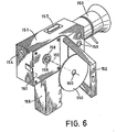
- Fig. 6 shows an electronic camera which is adapted to record video information on a rotary information disc 150.
- the camera comprises a main frame 151 on which there are arranged a pivotable cover 152, an objective 153, a viewfinder 154, a grip 155 and a number of controls 156 and 157.
- the information disc 150 can be fitted onto a turntable 158 on which a centring element 159 is located, the information disc being fitted onto said element with its central opening 160.
- a disc loader not shown, for pressing the information disc onto the turntable 158.
- the main frame 151 comprises a substantially flat frame plate 161 extending transversely of the axis of rotation 162 of the information disc.
- the whole or part of said frame plate is radiation-beam-transmissive and constitutes a shielding plate for an objective which is movable in the housing 151 of the camera. Via said objective video information can be recorded on the information disc with the aid of a radiation beam.
- the information disc may for example be of the type described in United States Patent Specification 4,074,282 (herewith incorporated by reference).
Landscapes
- Physics & Mathematics (AREA)
- Optics & Photonics (AREA)
- Optical Recording Or Reproduction (AREA)
- Optical Head (AREA)
- Manufacturing Optical Record Carriers (AREA)
- Liquid Crystal (AREA)
Claims (6)
dadurch gekennzeichnet, dass:
Priority Applications (1)
| Application Number | Priority Date | Filing Date | Title |
|---|---|---|---|
| AT81200784T ATE17616T1 (de) | 1980-07-31 | 1981-07-08 | Geraet zum aufzeichnen oder wiedergeben einer rotierenden informationsscheibe mittels eines strahlungsbuendels. |
Applications Claiming Priority (2)
| Application Number | Priority Date | Filing Date | Title |
|---|---|---|---|
| NL8004379A NL8004379A (nl) | 1980-07-31 | 1980-07-31 | Inrichting voor het met behulp van een stralingsbundel inschrijven en/of uitlezen van informatie op een roterende informatieschijf. |
| NL8004379 | 1980-07-31 |
Publications (2)
| Publication Number | Publication Date |
|---|---|
| EP0045537A1 EP0045537A1 (de) | 1982-02-10 |
| EP0045537B1 true EP0045537B1 (de) | 1986-01-22 |
Family
ID=19835686
Family Applications (1)
| Application Number | Title | Priority Date | Filing Date |
|---|---|---|---|
| EP81200784A Expired EP0045537B1 (de) | 1980-07-31 | 1981-07-08 | Gerät zum Aufzeichnen oder Wiedergeben einer rotierenden Informationsscheibe mittels eines Strahlungsbündels |
Country Status (11)
| Country | Link |
|---|---|
| US (1) | US4389717A (de) |
| EP (1) | EP0045537B1 (de) |
| JP (1) | JPS5753842A (de) |
| AT (1) | ATE17616T1 (de) |
| AU (1) | AU7352481A (de) |
| CA (1) | CA1183257A (de) |
| DD (1) | DD201738A5 (de) |
| DE (1) | DE3173556D1 (de) |
| ES (1) | ES8206897A1 (de) |
| HK (1) | HK75186A (de) |
| NL (1) | NL8004379A (de) |
Families Citing this family (9)
| Publication number | Priority date | Publication date | Assignee | Title |
|---|---|---|---|---|
| NL8402176A (nl) * | 1984-07-10 | 1986-02-03 | Philips Nv | Inrichting voor het met een stralingsvlek inschrijven en/of uitlezen van informatie op een roterende informatieplaat. |
| DE3524048A1 (de) * | 1985-07-05 | 1987-01-08 | Thomson Brandt Gmbh | Laser-plattenspieler mit einer schutzblende |
| DE3840311A1 (de) * | 1988-11-30 | 1990-05-31 | Thomson Brandt Gmbh | Optisches aufzeichnungs- und/oder wiedergabe-geraet |
| US5086422A (en) * | 1989-06-19 | 1992-02-04 | Ricoh Company, Ltd. | Optical disk apparatus |
| JP2826135B2 (ja) * | 1989-09-25 | 1998-11-18 | 株式会社リコー | 光ディスク駆動装置 |
| US5351228A (en) * | 1990-09-20 | 1994-09-27 | Ricoh Company Ltd. | Optical disk drive unit |
| US5787063A (en) * | 1990-09-20 | 1998-07-28 | Richoh Company, Ltd. | Disk drive unit having improved shutter mechanism |
| JP3320906B2 (ja) * | 1994-06-30 | 2002-09-03 | アルパイン株式会社 | ディスク装置 |
| JP2007310987A (ja) * | 2006-05-19 | 2007-11-29 | Fujitsu Ltd | 光記録媒体駆動装置および光ピックアップ |
Family Cites Families (9)
| Publication number | Priority date | Publication date | Assignee | Title |
|---|---|---|---|---|
| US2416135A (en) * | 1945-06-04 | 1947-02-18 | David Appleby | Phonographic apparatus |
| FR2126492A5 (de) * | 1971-02-08 | 1972-10-06 | Thomson Csf | |
| US3839601A (en) * | 1971-07-06 | 1974-10-01 | Gakken Co Ltd | Optical record sheet and device for reproducing sound therefrom |
| NL178283C (nl) * | 1975-08-28 | 1986-02-17 | Philips Nv | Afspeelinrichting, in het bijzonder videospeler. |
| US4038663A (en) * | 1975-09-23 | 1977-07-26 | U.S. Philips Corporation | Method of writing information with a modulated radiation beam onto an information storage medium and information storage medium particularly adapted to the method |
| US4003091A (en) * | 1976-03-08 | 1977-01-11 | International Business Machines Corporation | Transducer support and stabilizer |
| NL7605374A (nl) * | 1976-05-20 | 1977-11-22 | Philips Nv | Inrichting voor het met behulp van een stralen- bundel optisch uitlezen en/of beschrijven van een roterende plaat. |
| JPS52153705A (en) * | 1976-06-17 | 1977-12-21 | Teac Co | Optical disc regenerator |
| FR2396383A1 (fr) * | 1977-07-01 | 1979-01-26 | Thomson Brandt | Dispositif de sustentation d'un support d'information en forme de disque souple et lecteur de disque utilisant un tel dispositif |
-
1980
- 1980-07-31 NL NL8004379A patent/NL8004379A/nl not_active Application Discontinuation
- 1980-11-17 US US06/207,324 patent/US4389717A/en not_active Expired - Lifetime
-
1981
- 1981-07-08 AT AT81200784T patent/ATE17616T1/de not_active IP Right Cessation
- 1981-07-08 EP EP81200784A patent/EP0045537B1/de not_active Expired
- 1981-07-08 DE DE8181200784T patent/DE3173556D1/de not_active Expired
- 1981-07-28 JP JP56117204A patent/JPS5753842A/ja active Pending
- 1981-07-28 DD DD81232153A patent/DD201738A5/de unknown
- 1981-07-29 ES ES504391A patent/ES8206897A1/es not_active Expired
- 1981-07-29 AU AU73524/81A patent/AU7352481A/en not_active Abandoned
- 1981-07-30 CA CA000382926A patent/CA1183257A/en not_active Expired
-
1986
- 1986-10-09 HK HK751/86A patent/HK75186A/xx unknown
Also Published As
| Publication number | Publication date |
|---|---|
| JPS5753842A (en) | 1982-03-31 |
| ATE17616T1 (de) | 1986-02-15 |
| NL8004379A (nl) | 1982-03-01 |
| US4389717A (en) | 1983-06-21 |
| ES504391A0 (es) | 1982-08-16 |
| EP0045537A1 (de) | 1982-02-10 |
| DE3173556D1 (en) | 1986-03-06 |
| ES8206897A1 (es) | 1982-08-16 |
| DD201738A5 (de) | 1983-08-03 |
| CA1183257A (en) | 1985-02-26 |
| HK75186A (en) | 1986-10-17 |
| AU7352481A (en) | 1982-02-04 |
Similar Documents
| Publication | Publication Date | Title |
|---|---|---|
| KR100557798B1 (ko) | 디스크 장치 | |
| EP0045537B1 (de) | Gerät zum Aufzeichnen oder Wiedergeben einer rotierenden Informationsscheibe mittels eines Strahlungsbündels | |
| KR19980064688A (ko) | 광학픽업장치 및 광디스크장치 | |
| US5727111A (en) | Optical pick-up and light detecting cover therefor | |
| EP0196691A1 (de) | Elektro-optische Vorrichtung | |
| US6445674B1 (en) | Optical head apparatus and optical disk apparatus | |
| EP0124353B1 (de) | Plattenspieler für optische Platten | |
| US3977684A (en) | Playback apparatus, in particular a video player | |
| US7409695B2 (en) | Disc drive apparatus | |
| KR850003349Y1 (ko) | 방사비임으로서 회전정보 디스크상에 정보를 기록 및 재생시키기 위한장치 | |
| EP0064273A2 (de) | Gerät zum Verarbeiten von auf eine Scheibe optisch aufgenommener Information | |
| JP4888924B2 (ja) | 光記録媒体の読み出し又は書き込み装置 | |
| JP2553035Y2 (ja) | 光学ヘッド装置 | |
| JP3342390B2 (ja) | ディスク記録再生装置 | |
| JPS60160034A (ja) | 光学式デイスク・プレ−ヤ | |
| JP3800377B2 (ja) | ピックアップユニット | |
| JPH0917082A (ja) | 光ディスクドライブ装置 | |
| JP2566014B2 (ja) | 光学式情報記録再生装置 | |
| JPH0416310Y2 (de) | ||
| JPH0785493A (ja) | 光学ピックアップ | |
| JP2816017B2 (ja) | 光メモリ用ドライブ装置 | |
| JPS6352339A (ja) | 光学ヘツド | |
| JPS5824263Y2 (ja) | 光学的記録又は再生装置 | |
| JPH05181083A (ja) | ビーム照射装置 | |
| KR20070014038A (ko) | 디스크 장치 |
Legal Events
| Date | Code | Title | Description |
|---|---|---|---|
| PUAI | Public reference made under article 153(3) epc to a published international application that has entered the european phase |
Free format text: ORIGINAL CODE: 0009012 |
|
| AK | Designated contracting states |
Designated state(s): AT BE DE FR GB IT NL SE |
|
| 17P | Request for examination filed |
Effective date: 19820111 |
|
| RAP1 | Party data changed (applicant data changed or rights of an application transferred) |
Owner name: N.V. PHILIPS' GLOEILAMPENFABRIEKEN |
|
| GRAA | (expected) grant |
Free format text: ORIGINAL CODE: 0009210 |
|
| AK | Designated contracting states |
Designated state(s): AT BE DE FR GB IT NL SE |
|
| REF | Corresponds to: |
Ref document number: 17616 Country of ref document: AT Date of ref document: 19860215 Kind code of ref document: T |
|
| REF | Corresponds to: |
Ref document number: 3173556 Country of ref document: DE Date of ref document: 19860306 |
|
| ITF | It: translation for a ep patent filed | ||
| ET | Fr: translation filed | ||
| PGFP | Annual fee paid to national office [announced via postgrant information from national office to epo] |
Ref country code: AT Payment date: 19860715 Year of fee payment: 6 |
|
| PLBE | No opposition filed within time limit |
Free format text: ORIGINAL CODE: 0009261 |
|
| STAA | Information on the status of an ep patent application or granted ep patent |
Free format text: STATUS: NO OPPOSITION FILED WITHIN TIME LIMIT |
|
| 26N | No opposition filed | ||
| PGFP | Annual fee paid to national office [announced via postgrant information from national office to epo] |
Ref country code: NL Payment date: 19870731 Year of fee payment: 7 |
|
| PG25 | Lapsed in a contracting state [announced via postgrant information from national office to epo] |
Ref country code: AT Effective date: 19880708 |
|
| PG25 | Lapsed in a contracting state [announced via postgrant information from national office to epo] |
Ref country code: SE Effective date: 19880709 |
|
| PG25 | Lapsed in a contracting state [announced via postgrant information from national office to epo] |
Ref country code: BE Effective date: 19880731 |
|
| BERE | Be: lapsed |
Owner name: N.V. PHILIPS' GLOEILAMPENFABRIEKEN Effective date: 19880731 |
|
| PG25 | Lapsed in a contracting state [announced via postgrant information from national office to epo] |
Ref country code: NL Effective date: 19890201 |
|
| NLV4 | Nl: lapsed or anulled due to non-payment of the annual fee | ||
| PGFP | Annual fee paid to national office [announced via postgrant information from national office to epo] |
Ref country code: GB Payment date: 19900702 Year of fee payment: 10 |
|
| PGFP | Annual fee paid to national office [announced via postgrant information from national office to epo] |
Ref country code: FR Payment date: 19900720 Year of fee payment: 10 |
|
| PGFP | Annual fee paid to national office [announced via postgrant information from national office to epo] |
Ref country code: DE Payment date: 19900921 Year of fee payment: 10 |
|
| PG25 | Lapsed in a contracting state [announced via postgrant information from national office to epo] |
Ref country code: GB Effective date: 19910708 |
|
| GBPC | Gb: european patent ceased through non-payment of renewal fee | ||
| PG25 | Lapsed in a contracting state [announced via postgrant information from national office to epo] |
Ref country code: FR Effective date: 19920331 |
|
| PG25 | Lapsed in a contracting state [announced via postgrant information from national office to epo] |
Ref country code: DE Effective date: 19920401 |
|
| REG | Reference to a national code |
Ref country code: FR Ref legal event code: ST |
|
| EUG | Se: european patent has lapsed |
Ref document number: 81200784.7 Effective date: 19890510 |