EP0045558B1 - Méthode et appareil pour le mélange non agressif de courant liquide en circulation - Google Patents
Méthode et appareil pour le mélange non agressif de courant liquide en circulation Download PDFInfo
- Publication number
- EP0045558B1 EP0045558B1 EP81302557A EP81302557A EP0045558B1 EP 0045558 B1 EP0045558 B1 EP 0045558B1 EP 81302557 A EP81302557 A EP 81302557A EP 81302557 A EP81302557 A EP 81302557A EP 0045558 B1 EP0045558 B1 EP 0045558B1
- Authority
- EP
- European Patent Office
- Prior art keywords
- secondary flow
- flow pattern
- conduit
- fluid stream
- curved portions
- Prior art date
- Legal status (The legal status is an assumption and is not a legal conclusion. Google has not performed a legal analysis and makes no representation as to the accuracy of the status listed.)
- Expired
Links
- 239000012530 fluid Substances 0.000 title claims description 76
- 238000000034 method Methods 0.000 title claims description 15
- 239000007788 liquid Substances 0.000 claims description 3
- 230000006378 damage Effects 0.000 description 7
- 230000000694 effects Effects 0.000 description 7
- 239000003153 chemical reaction reagent Substances 0.000 description 4
- 238000004804 winding Methods 0.000 description 3
- WYTGDNHDOZPMIW-RCBQFDQVSA-N alstonine Natural products C1=CC2=C3C=CC=CC3=NC2=C2N1C[C@H]1[C@H](C)OC=C(C(=O)OC)[C@H]1C2 WYTGDNHDOZPMIW-RCBQFDQVSA-N 0.000 description 2
- 230000008859 change Effects 0.000 description 2
- 238000011109 contamination Methods 0.000 description 2
- 238000002955 isolation Methods 0.000 description 2
- 239000000463 material Substances 0.000 description 2
- 210000002966 serum Anatomy 0.000 description 2
- 102000004190 Enzymes Human genes 0.000 description 1
- 108090000790 Enzymes Proteins 0.000 description 1
- 230000009471 action Effects 0.000 description 1
- 230000002411 adverse Effects 0.000 description 1
- 230000008901 benefit Effects 0.000 description 1
- 230000015572 biosynthetic process Effects 0.000 description 1
- 238000010276 construction Methods 0.000 description 1
- 230000003247 decreasing effect Effects 0.000 description 1
- 239000011521 glass Substances 0.000 description 1
- 230000005484 gravity Effects 0.000 description 1
- 238000004519 manufacturing process Methods 0.000 description 1
- 238000005259 measurement Methods 0.000 description 1
- 230000007246 mechanism Effects 0.000 description 1
- 229920001296 polysiloxane Polymers 0.000 description 1
- -1 polytetrafluorethylene Polymers 0.000 description 1
- 229920001343 polytetrafluoroethylene Polymers 0.000 description 1
- 230000011218 segmentation Effects 0.000 description 1
- 230000007704 transition Effects 0.000 description 1
Images


Classifications
-
- B—PERFORMING OPERATIONS; TRANSPORTING
- B01—PHYSICAL OR CHEMICAL PROCESSES OR APPARATUS IN GENERAL
- B01F—MIXING, e.g. DISSOLVING, EMULSIFYING OR DISPERSING
- B01F25/00—Flow mixers; Mixers for falling materials, e.g. solid particles
- B01F25/40—Static mixers
- B01F25/42—Static mixers in which the mixing is affected by moving the components jointly in changing directions, e.g. in tubes provided with baffles or obstructions
- B01F25/43—Mixing tubes, e.g. wherein the material is moved in a radial or partly reversed direction
- B01F25/433—Mixing tubes wherein the shape of the tube influences the mixing, e.g. mixing tubes with varying cross-section or provided with inwardly extending profiles
- B01F25/4331—Mixers with bended, curved, coiled, wounded mixing tubes or comprising elements for bending the flow
-
- G—PHYSICS
- G01—MEASURING; TESTING
- G01N—INVESTIGATING OR ANALYSING MATERIALS BY DETERMINING THEIR CHEMICAL OR PHYSICAL PROPERTIES
- G01N35/00—Automatic analysis not limited to methods or materials provided for in any single one of groups G01N1/00 - G01N33/00; Handling materials therefor
- G01N35/08—Automatic analysis not limited to methods or materials provided for in any single one of groups G01N1/00 - G01N33/00; Handling materials therefor using a stream of discrete samples flowing along a tube system, e.g. flow injection analysis
Definitions
- This invention relates to an apparatus and method for the thorough mixing of a flowing fluid stream and, more particularly, to such apparatus and method as are particularly adapted for use in automated analytical devices of the continuous-flow type.
- Such systems may typically require thorough mixing, at reasonable flow rates and in conduits of reasonable inner diameter, of a blood serum sample and one or more reagents, within a period of less than ten seconds following mixing of sample and reagent.
- blood serum samples are passed as a continuous stream comprising successive sample segments separated by inert fluid segments, mixing of the reagent with such successive segments must be effected without adverse effect on the integrity and/or isolation of the successive sample segments, as would result from a device such as a mechanical stirrer.
- a typical prior art mixing device for flowing fluid streams comprises a conduit in the form of a helical mixing coil, e.g. as described in United States Patent 2,933,293.
- This mixing coil relies for its mixing effect primarily upon differences in specific gravities of the liquids to be mixed.
- As the stream flows through such a coil there is some limited mixing due to a secondary flow, but because of the generally invariant direction of fluid flow in the coils of the helix, i.e. counterclockwise as seen in the patent Figure 8, the secondary flow pattern is generally constant and of invariant orientation relative to the coil conduit.
- a method of thorough and rapid mixing of two or more components in a fluid which comprises flowing the fluid through an unobstructed conduit including curved portions and having a single inlet and a single outlet so as to define a single undivided passageway therein, the flowing stream having a primary flow pattern in the axial direction of the conduit and from the inlet to the outlet of the conduit, and a secondary flow pattern in the curved portions of the conduit, characterised in that: the curved portions sequentially establish at least two different secondary flow patterns in the stream as it flows through the conduit, the second of said secondary flow patterns be"xg established substantially immediately following the establishment of said first secondary flow pattern and prior to the substantial dissipation of the first secondary flow pattern, whereby said second secondary flow pattern destroys said first secondary flow pattern.
- the invention also provides an apparatus for the rapid and thorough mixing of two or more components in a fluid stream slowing therethrough, said apparatus comprising an unobstructed conduit having a single inlet and a single outlet so as to define an undivided flow passageway, characterised in that: said conduit comprises at least two curved portions which are in close proximity and are arranged so that, as a fluid stream flows through said conduit, a first secondary flow pattern is established therein in the first of said curved portions, and a second different secondary flow pattern is established therein in the second of said curved portions, said second secondary flow pattern being established substantially immediately following the establishment of said first secondary flow pattern and prior to the substantial dissipation of said first secondary flow pattern so as thereby to destroy said first secondary flow pattern.
- the conduits used in the invention are of simple design and construction, and require the use of only readily available low cost materials of proven dependability in the fabrication thereof, which ensures long periods of satisfactory, maintenance-free operation. Further, because of the greatly improved mixing achievable according to the invention, only a minimum length of conduit is required, and it can operate utilising flow velocities and at inner diameters generally well suited to automated analysis machines. Further, the conduits and method of the invention can achieve thorough mixing of each segment of a segmented flowing stream, while substantially precluding contamination between said segments.
- the flowing fluid stream may be either continuous or segmented.
- the mixing conduit comprises a plurality of interconnected bends or curved portions, which may be in the form of arcuate coils or sections, successive arcuate sections being operable to establish secondary flow patterns in differing orientations within the flowing fluid stream, or individual segments thereof.
- arcuate sections may be disposed in a same plane, if formed in serpentine fashion, or in non-parallel, preferably orthogonal, planes if formed in a tortuous fashion.
- the arcuate sections, or a series thereof may be formed in stacked fashion and located in essentially parallel planes.
- Secondary flow is the result of fluid transiting an arcuate section or other curved portion of a conduit and is evidenced by a pair of counter-rotating, generally circular flow patterns oriented perpendicular to bulk stream flow and generally symmetrically to a plane of symmetry which coincides generally with the plane of curvature of the curved portion.
- the secondary flow pattern established by a previous curved portion is destroyed and a new secondary flow pattern is created in an orientation dictated by the plane of curvature and the direction of circulation of the new curved portion.
- the planes of curvature of successive curved portions are identical but the direction of circulation of the secondary flow patterns is reversed.
- the destruction and re-establishment of these secondary flow patterns at each successive curved portion results in very turbulent mixing of a flowing stream having what would otherwise be stable secondary flow patterns. For a given flow velocity, complete mixing is achieved along a substantially reduced conduit length, as compared to prior art structures.
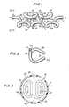
- the conduit is indicated generally at 10 and basically comprises a mixing coil 12.
- a segmented fluid stream wherein selected segments contain two or more components to be rapidly and thoroughly mixed, would be introduced to the mising coil 12 at the inlet end thereof as indicated at 14 for flow through the coil, and exit of the fluid stream from the outlet end of the coil as indicated at 16.
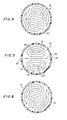
- Figures 8 and 9 illustrate the phenomenon of secondary flow in a fluid stream flowing in a representative prior art helical mixing coil and, also, illustrate the significant limitations on the mixing effects of secondary flow which are inherent in such mixing coil.
- a fluid stream flows in the indicated direction through a representative initial coil 18 of a prior art helical mixing coil, stable secondary flow circulation patterns will be developed in that flowing fluid stream.
- Such distortions result in the generation of stable secondary flow patterns oriented perpendicular to the flowing fluid stream, as illustrated generally at 30 and 32 in Figure 9. As shown, these secondary flow patterns will be generally symmetrical to a plane of symmetry or curvature as indicated at 40 and will contribute to the mixing of the flowing fluid stream.
- dead areas Certain portions of the flowing fluid stream, or what will hereinafter be termed "dead areas", as indicated generally at 42, 42', 44 and 44' in Figure 9, are not in these secondary flow circulation patterns. Since all of the subsequent coils of the representative prior art helical mixing coil here under discussion are generally parallel to initial coil 18 - see also, for example, Figure 1 of United States Letters Patent 2,933,293 - the orientation of the secondary flow circulation patterns 30 and 32, and of the plane of symmetry or curvature 40, relative to the mixing coil conduit, will remain substantially unchanged during flow of the fluid stream throughout the entire mixing coil. Accordingly, fluid stream components which reside in the dead areas 42, 42' and 44 and 44' will remain generally unmixed.
- the mixing coil 12 may comprise a plurality of interconnected arcuate sections having respective planes of curvature, which are non-parallel and, preferably, orthogonal. Such arcuate sections are indicated at 50, 52, 54, 56, 58, 60, 62, 64, 66, 68 and 70, respectively. It should be appreciated that a greater or lesser number of arcuate sections may be utilized, depending upon the particular mixing requirements.
- the tubing 72 which forms the mixing coil 12 may be made from any readily available, appropriately inert and durable material, for example polytetrafluorethylene or glass.
- the mixing coil 12 contains a relatively large number of abrupt turns or changes in direction per unit length to define in overall tortuous flow path.
- the twin circulating patterns in the secondary flow of the fluid stream are forced to abruptly change orientation by 90° when passing from arcuate section 58 and through arcuate section 60, and to abruptly again change orientation by 90° when passing from arcuate section 60 and through arcuate section 62.
- the resulting sequence of circulation patterns is illustrated in Figures 3-7.
- Each abrupt reorientation of the secondary flow circulation patterns in the flowing fluid stream, or segment completely destroys and re-establishes such secondary flow patterns therein.
- An efficient mixing results, due to the fact that turbulent mixing of the fluid stream, including dead areas, as therein indicated at 80, 80', 82 and 82', results during transition of the secondary flow circulation patterns to a new orientation, as illustrated in Figures 4 and 6.
- Figure 3 illustrates the orientation of the fully developed stable secondary flow circulation patterns indicated generally at 74 and 76, and plane of symmetry, indicated at 78, relative to the tubing 72 of the mixing coil 12 of a portion of the fluid stream flowing generally downwardly in arcuate coil section 58. As this same portion of the fluid stream passes.
- each arcuate section can define an angle greater or less than 90° relative to the preceding arcuate section, so long as such angle is sufficient to establish a new orientation of the secondary flow circulation patterns in the fluid stream relative to the inner wall of conduit 72.
- the entire length of mixing coil 12 may be less than 3.8 cm (14 inches) from arcuate section 50 to arcuate section 70; it being clear that fully ten such complete and abrupt destructions and re-establishments of the secondary flow patterns will advantageously occur in accordance with the teachings of our invention in that relatively short length.
- the dead areas, as indicated at 80, 80', 82 and 82', in the fluid stream are continuously disrupted during passage of the fluid stream between the respective arcuate sections defined in mixing coil 12.
- fluid contained in such dead areas is completely swept by the changing secondary flow patterns 74 and 76 to re-appear at markedly different locations relative to tubing 72 upon re-establishment of those stable, secondary flow patterns in the succeeding arcuate section.
- FIG. 10 Another embodiment of mixing apparatus of the present invention is indicated generally at 90 in Figure 10 and, as seen therein, comprises a conduit 92 having a fluid stream inlet 94 and a fluid stream outlet 96; and including generally arcuate sections 98, 100, 102 and 104, respectively, which in essence reverse upon themselves as shown to result in the formation of a generally serpentine mixing coil, and one wherein the longitudinal axis of the conduit 92 remains generally in the same plane.
- the mixing coil of our invention configured as depicted in Figure 10, it may be readily understood that the fluid stream flowing therethrough will be subjected to generally oppositely directed centrifugal forces attendant the transit by the fluid stream of successive ones of the arcuate sections of the coil.
- the fluid stream when flowing generally through arcuate section 98, the fluid stream will be subjected to generally upwardly directed centrifugal forces as indicated by the arrows 106 and 108 in Figure 10 to result in the establishment of secondary flow patterns in the fluid stream as illustrated at 110 and 112 in Figure 11. Subsequent flow of the fluid stream from arcuate section 98 into and through arcuate section 100 will result in a general reversal of the direction of these centrifugal forces to generally downwardly directed centrifugal forces as indicated by the arrows 114 and 116 in Figure 12, with attendant complete destruction of the secondary flow patterns 110 and 112 of Figure 11 and re-establishment thereof as illustrated at 118 and 120 in Figure 12.
- a further embodiment of the mixing apparatus of our invention may take the general form of that depicted in Figure 10, but wherein respective of the arcuate sections, or series thereof, as stacked in such manner that the longitudinal axes thereof lie in parallel or substantially parallel planes.
- a segmented fluid stream comprises alternating liquid sample segments separated by segments of an appropriate immiscible fluid, e.g. silicone.
- an appropriate immiscible fluid e.g. silicone.
- any inert immiscible fluid e.g. air
- Such fluid stream is reacted with appropriate reagents and requires thorough mixing with the same.
- the segmenting immiscible fluid prevents inter-segment contamination during flow along the system.
- the mixing action provided by the apparatus and method, as described hereinabove effects such mixing without destroying the integrity and/or isolation of the successive segments.
Landscapes
- Chemical & Material Sciences (AREA)
- Chemical Kinetics & Catalysis (AREA)
- Dispersion Chemistry (AREA)
- General Health & Medical Sciences (AREA)
- Analytical Chemistry (AREA)
- Biochemistry (AREA)
- Physics & Mathematics (AREA)
- General Physics & Mathematics (AREA)
- Immunology (AREA)
- Pathology (AREA)
- Life Sciences & Earth Sciences (AREA)
- Health & Medical Sciences (AREA)
- Physical Or Chemical Processes And Apparatus (AREA)
Claims (10)
Applications Claiming Priority (2)
| Application Number | Priority Date | Filing Date | Title |
|---|---|---|---|
| US06/175,222 US4422773A (en) | 1980-08-04 | 1980-08-04 | Apparatus and method for the non-invasive mixing of a flowing fluid stream |
| US175222 | 1998-10-19 |
Publications (2)
| Publication Number | Publication Date |
|---|---|
| EP0045558A1 EP0045558A1 (fr) | 1982-02-10 |
| EP0045558B1 true EP0045558B1 (fr) | 1985-04-24 |
Family
ID=22639444
Family Applications (1)
| Application Number | Title | Priority Date | Filing Date |
|---|---|---|---|
| EP81302557A Expired EP0045558B1 (fr) | 1980-08-04 | 1981-06-09 | Méthode et appareil pour le mélange non agressif de courant liquide en circulation |
Country Status (6)
| Country | Link |
|---|---|
| US (1) | US4422773A (fr) |
| EP (1) | EP0045558B1 (fr) |
| JP (1) | JPS5753228A (fr) |
| AU (1) | AU541368B2 (fr) |
| CA (1) | CA1242434A (fr) |
| DE (1) | DE3170103D1 (fr) |
Families Citing this family (41)
| Publication number | Priority date | Publication date | Assignee | Title |
|---|---|---|---|---|
| FR2530484B1 (fr) * | 1982-07-26 | 1989-09-08 | Sgn Soc Gen Tech Nouvelle | Procede et dispositif pour la dissolution de gaz dans un liquide |
| US4572435A (en) * | 1984-05-30 | 1986-02-25 | Owens-Corning Fiberglas Corporation | Foamable liquid distributing means |
| FR2570617B1 (fr) * | 1984-09-26 | 1986-12-26 | Nal Transfusion Sanguine Centr | Melangeur a duree de contact definie et reproductible entre une phase liquide et au moins une autre phase liquide ou solide |
| US4802835A (en) * | 1986-04-25 | 1989-02-07 | Colgate-Palmolive Company | Apparatus for making soap |
| FR2598558B1 (fr) * | 1986-05-07 | 1988-11-10 | Telecommunications Sa | Photodiode a avalanche hgcdte sensible aux rayonnements de longueur d'onde superieure a 2 mm |
| US5277494A (en) * | 1993-05-11 | 1994-01-11 | Graco | Fluid integrator |
| AU673798B3 (en) * | 1993-06-03 | 1996-11-21 | Atomaer Pty Ltd | Multiphase staged passive reactor |
| MY110990A (en) * | 1993-06-03 | 1999-07-31 | Atomaer Pty Ltd | Multiphase staged passive reactor |
| DE19525044A1 (de) * | 1995-07-10 | 1997-01-16 | Linde Ag | Verfahren und Vorrichtung zum Stoffeintrag in strömende Medien |
| US5730938A (en) * | 1995-08-09 | 1998-03-24 | Bio-Chem Laboratory Systems, Inc. | Chemistry analyzer |
| FR2763868B1 (fr) * | 1997-05-28 | 1999-08-20 | Enunivers | Procede et dispositif de brassage d'un fluide contenant de l'eau |
| WO1999004892A1 (fr) * | 1997-07-24 | 1999-02-04 | Axiva Gmbh | Melangeur continu a convection chaotique, echangeur thermique et reacteur |
| US6632014B2 (en) * | 2000-12-04 | 2003-10-14 | Yeda Research And Development Co., Ltd. | Device and method for mixing substances |
| US7264394B1 (en) | 2002-06-10 | 2007-09-04 | Inflowsion L.L.C. | Static device and method of making |
| US7041218B1 (en) | 2002-06-10 | 2006-05-09 | Inflowsion, L.L.C. | Static device and method of making |
| US7045060B1 (en) | 2002-12-05 | 2006-05-16 | Inflowsion, L.L.C. | Apparatus and method for treating a liquid |
| US7160025B2 (en) * | 2003-06-11 | 2007-01-09 | Agency For Science, Technology And Research | Micromixer apparatus and methods of using same |
| US8088425B2 (en) * | 2003-10-08 | 2012-01-03 | Kraft Foods Global Brands Llc | Apparatus and method for surface treatment of a food product |
| DK1725711T3 (da) * | 2004-03-08 | 2008-07-28 | Laitram Llc | Fremgangsmåde og apparat til opvarmning eller köling af födevarer |
| US20050274489A1 (en) * | 2004-06-10 | 2005-12-15 | Brand Joseph H | Heat exchange device and method |
| GB2425971B (en) * | 2005-05-11 | 2010-06-30 | Gaim Ltd | A Flow Distributor |
| US20060280027A1 (en) * | 2005-06-10 | 2006-12-14 | Battelle Memorial Institute | Method and apparatus for mixing fluids |
| JP4645834B2 (ja) * | 2005-09-09 | 2011-03-09 | 栗田工業株式会社 | エマルションポリマの一次又は二次希釈装置 |
| US20090122637A1 (en) * | 2007-11-14 | 2009-05-14 | Jan Kruyer | Sinusoidal mixing and shearing apparatus and associated methods |
| JP5248140B2 (ja) * | 2008-02-27 | 2013-07-31 | 旭サナック株式会社 | 混合塗料の供給装置 |
| WO2011094279A1 (fr) * | 2010-01-26 | 2011-08-04 | The Board Of Governors For Higher Education, State Of Rhode Island And Providence Plantations | Systèmes et procédés pour micromélangeur à labyrinthe planaire |
| US8485230B2 (en) * | 2011-09-08 | 2013-07-16 | Laor Consulting Llc | Gas delivery system |
| DE102012206399B4 (de) * | 2012-04-18 | 2018-01-04 | Egm-Holding-International Gmbh | Verfahren zur Emulsionsbehandlung |
| JP2014198324A (ja) * | 2013-03-29 | 2014-10-23 | ソニー株式会社 | マイクロ流路及びマイクロ流体デバイス |
| KR101816339B1 (ko) * | 2014-05-13 | 2018-01-08 | 주식회사 엘지화학 | 연속식 관형반응기를 이용한 클로로실란가스 제조방법 |
| EP3009006B1 (fr) * | 2014-10-17 | 2018-10-03 | Linde Aktiengesellschaft | Appareil, système et procédé pour le traitement d'un produit fluide |
| CN105289385A (zh) * | 2015-10-22 | 2016-02-03 | 上海交通大学 | 基于增强弯道二次流效应的扭曲弧形微混合器 |
| EP3386629B1 (fr) * | 2015-12-11 | 2022-08-10 | Trojan Technologies | Système de traitement de fluide |
| US10662527B2 (en) | 2016-06-01 | 2020-05-26 | Asm Ip Holding B.V. | Manifolds for uniform vapor deposition |
| WO2018041921A1 (fr) * | 2016-08-31 | 2018-03-08 | Curevac Ag | Dispositif de mélange pour la production d'une composition d'acide nucléique liquide |
| SG11202103494TA (en) * | 2018-10-08 | 2021-05-28 | Boehringer Ingelheim Int | Continuous flow reactor for viral inactivation |
| US11492701B2 (en) | 2019-03-19 | 2022-11-08 | Asm Ip Holding B.V. | Reactor manifolds |
| US12516414B2 (en) | 2019-03-19 | 2026-01-06 | Asm Ip Holding B.V. | Reactor manifolds |
| EP3741453B1 (fr) * | 2019-05-24 | 2023-07-19 | Otto-von-Guericke-Universität Magdeburg | Dispositif de mélange avec configuration enroulée inversée et son utilisation |
| KR20210048408A (ko) | 2019-10-22 | 2021-05-03 | 에이에스엠 아이피 홀딩 비.브이. | 반도체 증착 반응기 매니폴드 |
| CA3172861A1 (fr) * | 2020-06-29 | 2022-01-06 | Ingolfur Arnason | Appareil pour chauffer ou refroidir des aliments |
Family Cites Families (8)
| Publication number | Priority date | Publication date | Assignee | Title |
|---|---|---|---|---|
| DE715253C (de) * | 1939-01-01 | 1941-12-17 | Solvay Werke Ag Deutsche | Gefaellemischrinne mit zickzackfoermiger Fluessigkeitsfuehrung zur Behandlung von schaeumenden Abwaessern |
| US2450195A (en) * | 1946-09-21 | 1948-09-28 | William H Grantham | Adjustable pipe fitting assembly |
| FR1587902A (fr) * | 1968-09-10 | 1970-04-03 | ||
| US3704006A (en) * | 1971-01-25 | 1972-11-28 | Kenics Corp | Dispersion producing method |
| NL7403883A (nl) * | 1974-03-22 | 1975-09-24 | Philips Nv | Werkwijze en inrichting voor extraktie bij vloei- stoffen. |
| US3927868A (en) * | 1974-05-28 | 1975-12-23 | Thomas B Moore | Static-type mixer, and receptacle and method of packaging utilizing same |
| US4222671A (en) * | 1978-09-05 | 1980-09-16 | Gilmore Oscar Patrick | Static mixer |
| DE2839564C2 (de) | 1978-09-12 | 1982-10-21 | Hoechst Ag, 6000 Frankfurt | Vorrichtung mit Zu- und Abfuhr von Wärme und zum Mischen von flüssigen Medien |
-
1980
- 1980-08-04 US US06/175,222 patent/US4422773A/en not_active Expired - Lifetime
-
1981
- 1981-05-21 CA CA000378039A patent/CA1242434A/fr not_active Expired
- 1981-06-09 DE DE8181302557T patent/DE3170103D1/de not_active Expired
- 1981-06-09 EP EP81302557A patent/EP0045558B1/fr not_active Expired
- 1981-06-23 AU AU72068/81A patent/AU541368B2/en not_active Ceased
- 1981-08-04 JP JP56121500A patent/JPS5753228A/ja active Granted
Also Published As
| Publication number | Publication date |
|---|---|
| JPH0153090B2 (fr) | 1989-11-13 |
| EP0045558A1 (fr) | 1982-02-10 |
| AU541368B2 (en) | 1985-01-03 |
| CA1242434A (fr) | 1988-09-27 |
| US4422773A (en) | 1983-12-27 |
| AU7206881A (en) | 1982-02-11 |
| DE3170103D1 (en) | 1985-05-30 |
| JPS5753228A (en) | 1982-03-30 |
Similar Documents
| Publication | Publication Date | Title |
|---|---|---|
| EP0045558B1 (fr) | Méthode et appareil pour le mélange non agressif de courant liquide en circulation | |
| US4408893A (en) | Motionless mixing device | |
| US5866910A (en) | Flow-through photo-chemical reactor | |
| US4111402A (en) | Motionless mixer | |
| EP0229139B1 (fr) | Ameliorations apportees a des procedes et a des appareils de brassage | |
| US4179222A (en) | Flow turbulence generating and mixing device | |
| US3620506A (en) | Fluid-mixing device | |
| US4481154A (en) | Insert for placement in a vessel and method of forming the insert | |
| EP0360371A2 (fr) | Mélangeurs statiques | |
| EP0701474B1 (fr) | Reacteur passif etage interphase | |
| EP0604116A1 (fr) | Mélangeur statique | |
| JPH0817927B2 (ja) | 流体用定置式混合装置 | |
| WO1983002241A1 (fr) | Dispositif de traitement des eaux | |
| US3424437A (en) | Apparatus for mixing viscous fluids | |
| JP2813369B2 (ja) | 気体流から液体小滴を分離する装置 | |
| KR890010477A (ko) | 디퓨져 장치 | |
| GB2097910A (en) | Insert for placement in vessel | |
| US12364957B2 (en) | Mixing device with reversed coiled configuration and use thereof | |
| PL232144B1 (pl) | Mieszalnik statyczny | |
| RU2396500C1 (ru) | Вставка для турбулизации потока жидкости в трубчатом элементе | |
| SU975046A1 (ru) | Статический лопастной смеситель | |
| AU697093B2 (en) | Multiphase staged passive reactor | |
| SU1643914A1 (ru) | Теплообменник | |
| SU882545A1 (ru) | Тарелка пульсационной экстракционной колонны | |
| CA1136613A (fr) | Conduit melangeur a chicanes d'agitation disposees en paires alternantes |
Legal Events
| Date | Code | Title | Description |
|---|---|---|---|
| PUAI | Public reference made under article 153(3) epc to a published international application that has entered the european phase |
Free format text: ORIGINAL CODE: 0009012 |
|
| AK | Designated contracting states |
Designated state(s): BE CH DE FR GB IT NL SE |
|
| 17P | Request for examination filed |
Effective date: 19820805 |
|
| ITF | It: translation for a ep patent filed | ||
| ITF | It: translation for a ep patent filed | ||
| GRAA | (expected) grant |
Free format text: ORIGINAL CODE: 0009210 |
|
| AK | Designated contracting states |
Designated state(s): BE CH DE FR GB IT LI NL SE |
|
| REF | Corresponds to: |
Ref document number: 3170103 Country of ref document: DE Date of ref document: 19850530 |
|
| ET | Fr: translation filed | ||
| PLBE | No opposition filed within time limit |
Free format text: ORIGINAL CODE: 0009261 |
|
| STAA | Information on the status of an ep patent application or granted ep patent |
Free format text: STATUS: NO OPPOSITION FILED WITHIN TIME LIMIT |
|
| 26N | No opposition filed | ||
| REG | Reference to a national code |
Ref country code: CH Ref legal event code: PUE Owner name: TECHNICON INSTRUMENTS CORPORATION TRANSFER- TECHNI |
|
| ITPR | It: changes in ownership of a european patent |
Owner name: FUSIONI;REVGROUP PANTRY MIRROR CORP. |
|
| REG | Reference to a national code |
Ref country code: GB Ref legal event code: 732 |
|
| REG | Reference to a national code |
Ref country code: FR Ref legal event code: TP |
|
| NLS | Nl: assignments of ep-patents |
Owner name: TECHNICON INSTRUMENTS CORPORATION (A DELAWARE CORP |
|
| NLS | Nl: assignments of ep-patents |
Owner name: TECHNICON INSTRUMENTS CORPORATION (A DELAWARE CORP |
|
| ITTA | It: last paid annual fee | ||
| PGFP | Annual fee paid to national office [announced via postgrant information from national office to epo] |
Ref country code: CH Payment date: 19930504 Year of fee payment: 13 |
|
| PGFP | Annual fee paid to national office [announced via postgrant information from national office to epo] |
Ref country code: SE Payment date: 19930517 Year of fee payment: 13 |
|
| PGFP | Annual fee paid to national office [announced via postgrant information from national office to epo] |
Ref country code: BE Payment date: 19930614 Year of fee payment: 13 |
|
| PGFP | Annual fee paid to national office [announced via postgrant information from national office to epo] |
Ref country code: NL Payment date: 19930630 Year of fee payment: 13 |
|
| PG25 | Lapsed in a contracting state [announced via postgrant information from national office to epo] |
Ref country code: SE Effective date: 19940610 |
|
| PG25 | Lapsed in a contracting state [announced via postgrant information from national office to epo] |
Ref country code: LI Effective date: 19940630 Ref country code: CH Effective date: 19940630 Ref country code: BE Effective date: 19940630 |
|
| BERE | Be: lapsed |
Owner name: TECHNICON INSTRUMENTS CORP. Effective date: 19940630 |
|
| PG25 | Lapsed in a contracting state [announced via postgrant information from national office to epo] |
Ref country code: NL Effective date: 19950101 |
|
| EUG | Se: european patent has lapsed |
Ref document number: 81302557.4 Effective date: 19950110 |
|
| NLV4 | Nl: lapsed or anulled due to non-payment of the annual fee | ||
| REG | Reference to a national code |
Ref country code: CH Ref legal event code: PL |
|
| EUG | Se: european patent has lapsed |
Ref document number: 81302557.4 |
|
| PGFP | Annual fee paid to national office [announced via postgrant information from national office to epo] |
Ref country code: FR Payment date: 20000517 Year of fee payment: 20 |
|
| PGFP | Annual fee paid to national office [announced via postgrant information from national office to epo] |
Ref country code: DE Payment date: 20000518 Year of fee payment: 20 |
|
| PGFP | Annual fee paid to national office [announced via postgrant information from national office to epo] |
Ref country code: GB Payment date: 20000519 Year of fee payment: 20 |
|
| PG25 | Lapsed in a contracting state [announced via postgrant information from national office to epo] |
Ref country code: GB Free format text: LAPSE BECAUSE OF EXPIRATION OF PROTECTION Effective date: 20010608 |
|
| REG | Reference to a national code |
Ref country code: GB Ref legal event code: PE20 Effective date: 20010608 |