EP0045591A1 - Moteur à embrayage électromagnétique - Google Patents
Moteur à embrayage électromagnétique Download PDFInfo
- Publication number
- EP0045591A1 EP0045591A1 EP81303338A EP81303338A EP0045591A1 EP 0045591 A1 EP0045591 A1 EP 0045591A1 EP 81303338 A EP81303338 A EP 81303338A EP 81303338 A EP81303338 A EP 81303338A EP 0045591 A1 EP0045591 A1 EP 0045591A1
- Authority
- EP
- European Patent Office
- Prior art keywords
- clutch
- ring
- brake
- motor
- rotor
- Prior art date
- Legal status (The legal status is an assumption and is not a legal conclusion. Google has not performed a legal analysis and makes no representation as to the accuracy of the status listed.)
- Granted
Links
Images


Classifications
-
- F—MECHANICAL ENGINEERING; LIGHTING; HEATING; WEAPONS; BLASTING
- F16—ENGINEERING ELEMENTS AND UNITS; GENERAL MEASURES FOR PRODUCING AND MAINTAINING EFFECTIVE FUNCTIONING OF MACHINES OR INSTALLATIONS; THERMAL INSULATION IN GENERAL
- F16D—COUPLINGS FOR TRANSMITTING ROTATION; CLUTCHES; BRAKES
- F16D67/00—Combinations of couplings and brakes; Combinations of clutches and brakes
- F16D67/02—Clutch-brake combinations
- F16D67/06—Clutch-brake combinations electromagnetically actuated
-
- H—ELECTRICITY
- H02—GENERATION; CONVERSION OR DISTRIBUTION OF ELECTRIC POWER
- H02K—DYNAMO-ELECTRIC MACHINES
- H02K7/00—Arrangements for handling mechanical energy structurally associated with dynamo-electric machines, e.g. structural association with mechanical driving motors or auxiliary dynamo-electric machines
- H02K7/10—Structural association with clutches, brakes, gears, pulleys or mechanical starters
- H02K7/112—Structural association with clutches, brakes, gears, pulleys or mechanical starters with friction clutches in combination with brakes
- H02K7/1125—Magnetically influenced friction clutches and brakes
Definitions
- the present invention relates to an electromagnetic clutch motor having an electromagnetic power transmission-mechanism, adapted for use as the driving source of industrial sewing machine.
- the electromagntic clutch of the kind described has a spreading use as the driving power source of industrial sewing machines.
- a large pulsation of the torque is caused to generate a large noise due to the presence of play between the spline and the discs.
- the magnetic circuit has three gaps. Two out of these three gaps are radial gaps so that they do not produce any attracting force. These two gaps, however, are inevitably large because they are the gaps between a rotary part and a sationary part. In consequence, the magnetic circuit can have only low efficiency of production of attracting force in response to the electric input (ampere turn) to the clutch coil and the brake coil.
- an object of the invention is to provide an electromagnetic clutch motor comprising a flywheel fixed to a motor shaft, a clutch ring secured to the flywheel non-rotatably but axially movably, a bracket supporting an output shaft, a brake ring secured to the bracket non-rotatably but axially movably, a clutch rotor fixed to the output shaft, and electromagnetic means adapted to selectively press the clutch ring or brake ring to the clutch rotor by electromagnetic force, thereby to permit the transmission of a large torque with small ampere turn and with reduced level of noise.
- Another object of the invention is to provide an electromagnetic clutch motor of the type stated above, wherein the clutch ring and the brake ring are pressed by a clutch spring and a brake spring thereby to diminish the time lag in acceleration and deceleration of the clutch rotor, i.e. the output shaft, while avoiding the generation of 'noise due to collision between the clutch and brake rings and the clutch rotor, and, by selecting the spring force of the brake spring to be greater than the spring force of the clutch spring, the unnecessary idling of the output shaft is avoided.
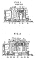
- a clutch coil 1 and a brake coil 2 are embedded in a clutch stator core 3 and a brake stator core 4, respectively. These clutch stator core 3 and the brake stator core 4 and fixed to the bracket 5.
- a clutch ring 7 is fixed to a flywheel 6 adapted to be continuously driven by a motor.
- a clutch disc 9 having a lining 8 and a brake disd 10 having a lining 8' are splined to an output shaft 15 coaxial with the motor shaft 11, in such a manner as not to be able to rotate relatively to the output shaft 15 but able to move axially on the latter.
- the arrangement is such that, as the clutch coil 1 is energized, a magnetic flux 101 is produced to generate a magnetic attracting force between the clutch ring 7 and the clutch disc 9 to displace the latter 9 to the left to bring the lining 8 into frictional engagement with the clutch ring 7, thereby to permit the transmission of the torque to the output shaft 15.
- the electric current supplied to the clutch coil 1 can be controlled by a speed controller (not shown) top control the speed of rotation of the output shaft 15.
- a speed controller not shown
- top control the speed of rotation of the output shaft 15.
- a reference numeral 12 designates a ball bearing
- a reference numeral 13 denotes a gap adjusting screw.
- the clutch disc 9 and the brake disc 10 are slided along the spline on the output shaft 15 to perform the transmission of the torque and the braking power.
- This type of electromagnetic clutch motor finds a spreading use, as stated before, as the driving power source of industrial sewing machine. In such a use, there is a large pulsation of torque to permit the generation of noise due to the play or looseness of the spline.
- the magnetic circuit includes three gaps two of which are radial gaps which do not contribute at all to the production of the magnetic attracting force. These gaps are, however, inevitably large because they are the gaps between the rotary and stationary parts. In consequence, the magnetic circuit can have only a low efficiency of production of attracting force in response to the electric current (ampere turn) supplied to the clutch coil 1 and the brake coil 2.
- an electromagnetic clutch motor of the invention has a motor bracket 21 and a -clutch bracket 22 which are secured to each other at three screws 23, only one of which is shown.
- a flywheel 25 is fixed to a motor shaft 24 which in turn is fixed to a motor rotor so that the flywheel 25 rotates as a unit with the motor rotor.
- a clutch coil 26 and a brake coil 29 are embedded, respectively, in a clutch stator core 27 and a brake stator core 30 which in turn are fixed to a clutch bracket 22.
- the clutch stator core 27 and the brake stator core 30 are provided with portions 28 and 31 of reduced cross-sectional area.
- a plurality of cylindrical pins 32 are mounted in the circumferential direction on the flywheel 25, and are fixed by means of screws 33.
- a metal bearing 34 as a sliding member is carried by the pins 32 with gaps of an order of several tens of microns so as to be able to slide in the axial direction relatively to the pins 32.
- a peripheral groove 35 for receiving an "0" ring 36 as a buffer material is formed in the outer periphery of the metal bearing 34..
- the "0" ring 36 is lightly presses into a recess in the clutch ring 37 so that the clutch ring 37 is movable as a unit with the metal bearing 34 in the axial direction of the pins 32.
- the same construction applies to the brake side.
- aplura- lity of pins 38 are fixed to the be bracket 22 by means of screws 39.
- a brake ring 42 is mounted axially movably on the pins 38 through the medium of a metal bearing 40 and an "0" ring 41.
- Linings 45 and 46 are bonded to both sides of a clutch rotor 44 made of a light metal such as aluminum or a synthetic resin, so as to oppose to the clutch ring 37 and the brake ring 42.
- the clutch rotor 44 is fixed by means of screws 47 to the output shaft 43. These members are supported by the motor shaft 24 and the bracket 22 through bearings 48 and 49.
- This type of electromagnetic clutch motor finds its major use as the driving power source of industrial sewing machine and, therefore, is required to have a good response to the demand for acceleration and deceleration of the output shaft 43 for attaining a high sewing efficiency.
- it is a common requisite to have a function of stopping the sewing needle at a predetermined position. In order to achieve a precise stopping, it is necessary to minimize the angle of slipping before the stopping from the moment of receipt of the stopping instruction. To this end, it is necessary to diminish the inertia of the output shaft 43 as much as possible. This is the reason why the clutch rotor 44 fixed to the output shaft 43 is made of a light metal such as aluminum or a synthetic resin.
- FRP fiber reinforced plastics
- unsaturated polyester resin reinforced with glass fiber is suitably used as the material of the clutch rotor 44, because of a large mechanical strength, high dimensional precision and a high heat resistance which in turn promises a small distortion due to heat.
- This material has a specific weight which is as small as 1.7 so that the inertia is decreased correspondingly to reduce the inertia of the output shaft to a level of about 30 % of that in the conventional apparatus shown in Fig. 1, to ensure a good acceleration and deceleration characteristic of the electromagnetic clutch motor.
- the clutch rotor made of synthetic resin serves to suppress squeal noises. Uncomfotable noises of high frequencies which might be produced by the engagement of clutches or brakes are effectively suppressed by selecting suitable synthetic resins or by adding a small amount of rubber powders.
- the clutch rotor 44 has a construction as shown in Fig. 4.
- the clutch rotor 44 preferably has a keyway 50 for preventing the clutch rotor 44 from slipping-relatively to the output shaft 43, as well as a plurality of radial ribs 51 bridging both sides thereof where the friction members are adhered.
- these ribs ensure the sufficiently high mechanical strength while the amount of material used is diminished to reduce both of cost and inertia.
- this clutch rotor 44 since this clutch rotor 44 has a form resembling an impeller, it can serve also as a fan to distribute cooling air to every portions of the electromagnetic clutch motor.
- the linings 45,46 are adhered to both sides of the clutch rotor 44.
- the linings 45,46 are possibly adhered to the clutch ring 37 and the brake ring 42 while the surfaces of the aluminum clutch rotor 44 for making frictional engagement with these linings 45,46 are treated by an alumite treatment or chromium plating to improve the weare resistance.
- the electromagnetic clutch motor of the first embodiment having the heretofore described construction operates in a manner explained hereinbelow.
- a magnet flux 103 is produced to act to the clutch ring 37 to the right because the clutch stator core 27 is fixed to the clutch bracket 22.
- the clutch ring 37 is brought into frictional engagement with the clutch rotor 44 through the lining 45, so that the torque of the motor is transmitted to the output shaft 43.
- a gap of an order of 0.5 to 1.0 mm is preserved in this state between the clutch ring 37 and the end surface of the clutch stator core 27.
- the linings 45 and 46 are made mainly of compressed cork, so that they are worn out gradually as a result of repeated frictional engagement with the clutch ring 37 and the brake ring 42. In consequence, the gap between the end surface of the clutch stator core 27 and the clutch ring 37, as well as the gap between the end surface of the brake stator core 30 and the brake ring 42, is reduced to cause an increase of the magnetic attracting force. As will be seen form curve A in Fig. 5, the magnetic attracting force is changed in a parabolic relation to the change in the gap. In contrast to the conventional apparatus shown in Fig. 1, the arrangement heretofore described permits the formation of an efficient magnetic circuit because both of two gaps contributes to the production of the magnetic force. On the other hand, however, the attracting force is rapidly increased as the result of wear in the linings 45 and 46 to promote the wear of these linings 45,46 or to shorten the life of the ball bearings 48,49.
- the clutch stator core 27 and the brake stator core 30 are partially notched to have portions 28,31 of reduced cross-sectional areas, thereby to reduce the rate of change of the magnetic attracting force in relation to the change of the gap as shown by curve B of Fig. 5.
- the influence, i.e. the reduction of attracting force, by these notches is not so appreciable, but the increase of the attracting force is considerably suppressed when the gap has become smaller as the result of the wear of the linings 41 and 42.
- the clutch stator core 27 and the brake stator core 30 are magnetically saturated due to the presence of the portions 28,31 of the smaller cross-sectional area to suppress further increase of the magnetic fluxes 103 and 104. It is, therefore, possible to obviate the problems of promotion of wear of the linings 45,46 and the shortening of the life of the ball bearings 48,49 due to excessive magnetic attracting force which in turn is caused by the wear of the linings 45,46.
- the portions of the reduced cross-sectional areas may be formed at portions other than the illustrated positions, and the position can suitably be selected to facilitate the fabrication. The cross-sectional areas of these portions can easily be determined in accordance with the B-H characteristic of the iron material used.
- the electromagnetic clutch motor of the kind described finds its major use as the driving power source of industrial sewing machine in which a large pulsation of torque takes place inevitably.
- This pulsation of torque in turn tends to generate noize due to vibration afforded when there is a large gap between the pins 32 and the metal bearing 34 or between the pins 38 and the metal bearing 40.
- the clutch ring 37 and the brake ring 42 are thermally expanded due to the heat generated in the lining to further reduce the gap, resulting in a difficulty in the axial movement of the rings to fail the safe torque transmitting function.
- the clutch ring 37 and the brake ring 42 are thermally expanded due to the heat generated by the friction at the linings 45,46 to increase the diameter of the pitch circle of attaching of the metal bearings 34,40 to nullify the aforementioned gap to cause a contact between the metal bearing 34 and the pins 32, as well as between the metal bearing 40 and the pins 38, to prohibit the axial movement of the clutch ring 37 and the brake ring 42. In such a state, it is not possible to perform the torque transmission and braking functions.
- the clutch ring 37 is axially movably attached through the metal bearing 34 to pins 32 which in turn are fixed to the flywheel 25.
- the clutch ring 37 are lightly pressed against the lining 45 by means of a clutch spring 52.
- the brake ring 42 is axially movably attached through the metal bearing 40 to the pins 38 fixed to the bracket 22, and is lightly pressed against the lining 46 by means of the brake spring 53.
- the output shaft 43 rotates unintentionally even when the clutch coil 26 is not energized, because the clutch ring 37 is lightly pressed aganinst the lining 45 by the clutch spring 52.
- the pressing force exerted by the brake spring 53 is selected to be greater than that exerted by the clutch spring 52 to obtain a sufficient braking force to prevent the output shaft 34 from rotating unintentionally.
Landscapes
- Engineering & Computer Science (AREA)
- General Engineering & Computer Science (AREA)
- Power Engineering (AREA)
- Physics & Mathematics (AREA)
- Electromagnetism (AREA)
- Mechanical Engineering (AREA)
- Connection Of Motors, Electrical Generators, Mechanical Devices, And The Like (AREA)
- Braking Arrangements (AREA)
Applications Claiming Priority (10)
| Application Number | Priority Date | Filing Date | Title |
|---|---|---|---|
| JP10612580A JPS5731351A (en) | 1980-07-31 | 1980-07-31 | Electromagnetic clutch motor |
| JP106125/80 | 1980-07-31 | ||
| JP162425/80 | 1980-11-17 | ||
| JP162426/80 | 1980-11-17 | ||
| JP55162426A JPS5785544A (en) | 1980-11-17 | 1980-11-17 | Electromagnetic clutch motor |
| JP162424/80 | 1980-11-17 | ||
| JP55162424A JPS5785542A (en) | 1980-11-17 | 1980-11-17 | Electromagnetic clutch motor |
| JP55162425A JPS5785543A (en) | 1980-11-17 | 1980-11-17 | Electromagnetic clutch motor |
| JP13438/81 | 1981-01-30 | ||
| JP56013438A JPS57129149A (en) | 1981-01-30 | 1981-01-30 | Electromagnetic clutch motor |
Publications (2)
| Publication Number | Publication Date |
|---|---|
| EP0045591A1 true EP0045591A1 (fr) | 1982-02-10 |
| EP0045591B1 EP0045591B1 (fr) | 1985-04-24 |
Family
ID=27519506
Family Applications (1)
| Application Number | Title | Priority Date | Filing Date |
|---|---|---|---|
| EP81303338A Expired EP0045591B1 (fr) | 1980-07-31 | 1981-07-21 | Moteur à embrayage électromagnétique |
Country Status (4)
| Country | Link |
|---|---|
| US (1) | US4429773A (fr) |
| EP (1) | EP0045591B1 (fr) |
| CA (1) | CA1204068A (fr) |
| DE (1) | DE3170120D1 (fr) |
Cited By (5)
| Publication number | Priority date | Publication date | Assignee | Title |
|---|---|---|---|---|
| EP0067662A1 (fr) * | 1981-06-11 | 1982-12-22 | Matsushita Electric Industrial Co., Ltd. | Moteur à embrayage à solénoide comportant des éléments axialement ajustables |
| DE3212305C1 (de) * | 1982-04-02 | 1983-10-13 | Zahnradfabrik Friedrichshafen Ag, 7990 Friedrichshafen | Elektromagnetisch betätigbare Reibungskupplungs-Brems-Kombination |
| EP0130344A1 (fr) * | 1983-06-01 | 1985-01-09 | Quick-Rotan Elektromotoren GmbH | Moteur d'accouplement |
| EP0469342A1 (fr) * | 1990-07-31 | 1992-02-05 | Eaton Corporation | Assemblage d'accouplement |
| CN104810971A (zh) * | 2015-05-14 | 2015-07-29 | 吴凤松 | 电机内置碟刹 |
Families Citing this family (7)
| Publication number | Priority date | Publication date | Assignee | Title |
|---|---|---|---|---|
| IT8153826U1 (it) * | 1981-11-20 | 1983-05-20 | Mazzini Motori | Gruppo motore posizionatore per macchine per cucire. |
| CS234124B1 (en) * | 1981-12-16 | 1985-04-16 | Jan Pajgrt | Coupling mechanismes especially for weaving machines |
| DE3508227C1 (de) * | 1985-03-08 | 1986-06-05 | Frankl & Kirchner GmbH & Co KG Fabrik für Elektromotoren u. elektrische Apparate, 6830 Schwetzingen | Elektromagnetisch betaetigbare Reibungsbrems- und Kupplungsvorrichtung fuer einen elektromotorischen Antrieb,insbesondere fuer Industrie-Naehmaschinen |
| US4643091A (en) * | 1985-11-25 | 1987-02-17 | Ncr Corporation | Electromagnetic clutch-brake positioning assembly |
| JPH0678771B2 (ja) * | 1988-08-05 | 1994-10-05 | 神鋼電機株式会社 | 電磁クラッチ |
| DE10058199A1 (de) * | 2000-11-23 | 2002-07-11 | Zahnradfabrik Friedrichshafen | Vorrichtung zum Führen eines Antriebsmoments |
| TWI701367B (zh) * | 2018-01-25 | 2020-08-11 | 賀欣機械廠股份有限公司 | 縫紉機驅動馬達之組裝結構 |
Citations (6)
| Publication number | Priority date | Publication date | Assignee | Title |
|---|---|---|---|---|
| CH319731A (fr) * | 1954-06-01 | 1957-02-28 | Mieville Andre | Appareil pour le freinage d'un moteur électrique |
| US2962139A (en) * | 1955-04-23 | 1960-11-29 | Ite Circuit Breaker Ltd | Solenoid operated clutch-brake device |
| DE1227990B (de) * | 1962-10-26 | 1966-11-03 | Siemens Ag | Scheibenbremse fuer Elektromotoren |
| US3487438A (en) * | 1967-05-06 | 1969-12-30 | Quick Rotan Becker & Co | Clutch and brake arrangements for a motor |
| DE2135821A1 (de) * | 1970-08-05 | 1972-02-10 | Warner Electric Brake & Clutch | Reibungsvorrichtung |
| FR2374765A1 (fr) * | 1976-12-20 | 1978-07-13 | Quick Rotan Becker & Notz Kg | Moteur electrique a embrayage et a frein |
Family Cites Families (7)
| Publication number | Priority date | Publication date | Assignee | Title |
|---|---|---|---|---|
| FR878468A (fr) | 1941-09-01 | 1943-01-21 | Schneider & Cie | Perfectionnements aux accouplements à friction à disques multiples |
| US2659830A (en) | 1951-12-13 | 1953-11-17 | Warner Electric Brake & Clutch | Combined motor and clutch |
| US3504773A (en) | 1968-08-29 | 1970-04-07 | Bendix Corp | Dual armature electromagnetic clutch and brake |
| DE2031834B2 (de) | 1970-06-26 | 1979-02-01 | Frankl & Kirchner Gmbh & Co Kg Fabrik Fuer Elektromotoren U. Elektrische Apparate, 6830 Schwetzingen | Elektromotorischer Regel- und Steuerantrieb, insbesondere für Industrie-Nähmaschinen |
| US3674122A (en) | 1970-11-12 | 1972-07-04 | Warner Electric Brake & Clutch | Magnetic friction clutch-brake unit |
| CH517402A (de) | 1970-12-15 | 1971-12-31 | Delmoran Ag | Kupplungsmotor |
| GB1562740A (en) | 1976-06-29 | 1980-03-12 | Mo Avtomobilnyj Zavod Im I A L | Piston/cylinder unit including means for adjusting the effective piston strokes |
-
1981
- 1981-07-17 CA CA000382001A patent/CA1204068A/fr not_active Expired
- 1981-07-21 DE DE8181303338T patent/DE3170120D1/de not_active Expired
- 1981-07-21 EP EP81303338A patent/EP0045591B1/fr not_active Expired
- 1981-07-21 US US06/287,074 patent/US4429773A/en not_active Expired - Fee Related
Patent Citations (6)
| Publication number | Priority date | Publication date | Assignee | Title |
|---|---|---|---|---|
| CH319731A (fr) * | 1954-06-01 | 1957-02-28 | Mieville Andre | Appareil pour le freinage d'un moteur électrique |
| US2962139A (en) * | 1955-04-23 | 1960-11-29 | Ite Circuit Breaker Ltd | Solenoid operated clutch-brake device |
| DE1227990B (de) * | 1962-10-26 | 1966-11-03 | Siemens Ag | Scheibenbremse fuer Elektromotoren |
| US3487438A (en) * | 1967-05-06 | 1969-12-30 | Quick Rotan Becker & Co | Clutch and brake arrangements for a motor |
| DE2135821A1 (de) * | 1970-08-05 | 1972-02-10 | Warner Electric Brake & Clutch | Reibungsvorrichtung |
| FR2374765A1 (fr) * | 1976-12-20 | 1978-07-13 | Quick Rotan Becker & Notz Kg | Moteur electrique a embrayage et a frein |
Cited By (6)
| Publication number | Priority date | Publication date | Assignee | Title |
|---|---|---|---|---|
| EP0067662A1 (fr) * | 1981-06-11 | 1982-12-22 | Matsushita Electric Industrial Co., Ltd. | Moteur à embrayage à solénoide comportant des éléments axialement ajustables |
| DE3212305C1 (de) * | 1982-04-02 | 1983-10-13 | Zahnradfabrik Friedrichshafen Ag, 7990 Friedrichshafen | Elektromagnetisch betätigbare Reibungskupplungs-Brems-Kombination |
| EP0130344A1 (fr) * | 1983-06-01 | 1985-01-09 | Quick-Rotan Elektromotoren GmbH | Moteur d'accouplement |
| US4643282A (en) * | 1983-06-01 | 1987-02-17 | Quick-Rotan Elektromotoren Gmbh | Motor having an electromagnetically actuated friction clutch and friction brake |
| EP0469342A1 (fr) * | 1990-07-31 | 1992-02-05 | Eaton Corporation | Assemblage d'accouplement |
| CN104810971A (zh) * | 2015-05-14 | 2015-07-29 | 吴凤松 | 电机内置碟刹 |
Also Published As
| Publication number | Publication date |
|---|---|
| EP0045591B1 (fr) | 1985-04-24 |
| US4429773A (en) | 1984-02-07 |
| CA1204068A (fr) | 1986-05-06 |
| DE3170120D1 (en) | 1985-05-30 |
Similar Documents
| Publication | Publication Date | Title |
|---|---|---|
| US4643282A (en) | Motor having an electromagnetically actuated friction clutch and friction brake | |
| US3487438A (en) | Clutch and brake arrangements for a motor | |
| US4429773A (en) | Electromagnetic clutch and brake | |
| US4703841A (en) | Adjustable electromagnetic clutch brake | |
| US3581855A (en) | Electromagnetic clutch and brake | |
| US3750781A (en) | Electric-motor with built-in electromagnetic disk clutch and brake | |
| US4410819A (en) | Electromagnetic coupling device | |
| GB1341907A (en) | Clutch/brake unit | |
| US3679034A (en) | Self-adjusting electromagnetic clutch | |
| US3724619A (en) | Self-adjusting electromagnetic clutch-brake | |
| US4172985A (en) | Electric coupling and brake motor | |
| US4049089A (en) | Electromagnetic brake assembly | |
| US4598804A (en) | Motor drive system | |
| US3214084A (en) | Electromagnetic friction device and compressor control for same | |
| US3473639A (en) | Transmission with electromagnetic brake and clutches | |
| US4589534A (en) | Electromechanical driving system with variable speed | |
| US3600616A (en) | Clutch motor with electromagnetically operated auxiliary braking means | |
| KR860000256B1 (ko) | 전자클러치 모우터 | |
| US4505366A (en) | Sewing machine motor unit | |
| KR840001804Y1 (ko) | 전자클러치 모우터 | |
| JPH0645708Y2 (ja) | 電磁連結装置 | |
| JPS60125139A (ja) | 電磁ブレ−キ付電動機 | |
| JPS6243420B2 (fr) | ||
| JPS6311858B2 (fr) | ||
| JPS6217943B2 (fr) |
Legal Events
| Date | Code | Title | Description |
|---|---|---|---|
| PUAI | Public reference made under article 153(3) epc to a published international application that has entered the european phase |
Free format text: ORIGINAL CODE: 0009012 |
|
| AK | Designated contracting states |
Designated state(s): DE FR GB |
|
| 17P | Request for examination filed |
Effective date: 19820625 |
|
| GRAA | (expected) grant |
Free format text: ORIGINAL CODE: 0009210 |
|
| AK | Designated contracting states |
Designated state(s): DE FR GB |
|
| REF | Corresponds to: |
Ref document number: 3170120 Country of ref document: DE Date of ref document: 19850530 |
|
| ET | Fr: translation filed | ||
| PLBE | No opposition filed within time limit |
Free format text: ORIGINAL CODE: 0009261 |
|
| STAA | Information on the status of an ep patent application or granted ep patent |
Free format text: STATUS: NO OPPOSITION FILED WITHIN TIME LIMIT |
|
| 26N | No opposition filed | ||
| PGFP | Annual fee paid to national office [announced via postgrant information from national office to epo] |
Ref country code: FR Payment date: 19930610 Year of fee payment: 13 |
|
| PGFP | Annual fee paid to national office [announced via postgrant information from national office to epo] |
Ref country code: GB Payment date: 19930615 Year of fee payment: 13 |
|
| PG25 | Lapsed in a contracting state [announced via postgrant information from national office to epo] |
Ref country code: GB Effective date: 19940721 |
|
| GBPC | Gb: european patent ceased through non-payment of renewal fee |
Effective date: 19940721 |
|
| PG25 | Lapsed in a contracting state [announced via postgrant information from national office to epo] |
Ref country code: FR Effective date: 19950331 |
|
| REG | Reference to a national code |
Ref country code: FR Ref legal event code: ST |
|
| PGFP | Annual fee paid to national office [announced via postgrant information from national office to epo] |
Ref country code: DE Payment date: 19950725 Year of fee payment: 15 |
|
| PG25 | Lapsed in a contracting state [announced via postgrant information from national office to epo] |
Ref country code: DE Effective date: 19970402 |