EP0045632B1 - Tuyau flexible - Google Patents
Tuyau flexible Download PDFInfo
- Publication number
- EP0045632B1 EP0045632B1 EP81303493A EP81303493A EP0045632B1 EP 0045632 B1 EP0045632 B1 EP 0045632B1 EP 81303493 A EP81303493 A EP 81303493A EP 81303493 A EP81303493 A EP 81303493A EP 0045632 B1 EP0045632 B1 EP 0045632B1
- Authority
- EP
- European Patent Office
- Prior art keywords
- pipe
- rings
- keepers
- pipe according
- bars
- Prior art date
- Legal status (The legal status is an assumption and is not a legal conclusion. Google has not performed a legal analysis and makes no representation as to the accuracy of the status listed.)
- Expired
Links
- 229910000831 Steel Inorganic materials 0.000 claims abstract description 26
- 239000010959 steel Substances 0.000 claims abstract description 26
- 241000239290 Araneae Species 0.000 claims abstract description 9
- 239000012530 fluid Substances 0.000 claims abstract description 9
- 239000002184 metal Substances 0.000 claims description 6
- 229910052751 metal Inorganic materials 0.000 claims description 6
- 239000013536 elastomeric material Substances 0.000 claims description 3
- 229910001220 stainless steel Inorganic materials 0.000 abstract description 9
- 239000010935 stainless steel Substances 0.000 abstract description 9
- 239000003129 oil well Substances 0.000 abstract description 6
- 239000004033 plastic Substances 0.000 abstract description 6
- 229920003023 plastic Polymers 0.000 abstract description 6
- 238000005452 bending Methods 0.000 abstract 1
- 229920001903 high density polyethylene Polymers 0.000 abstract 1
- 230000000717 retained effect Effects 0.000 abstract 1
- 239000000463 material Substances 0.000 description 5
- 239000004743 Polypropylene Substances 0.000 description 3
- -1 polypropylene Polymers 0.000 description 3
- 229920001155 polypropylene Polymers 0.000 description 3
- 210000002435 tendon Anatomy 0.000 description 3
- 239000004952 Polyamide Substances 0.000 description 2
- 238000002347 injection Methods 0.000 description 2
- 239000007924 injection Substances 0.000 description 2
- 229920002647 polyamide Polymers 0.000 description 2
- 244000043261 Hevea brasiliensis Species 0.000 description 1
- 208000003618 Intervertebral Disc Displacement Diseases 0.000 description 1
- 239000004677 Nylon Substances 0.000 description 1
- XAGFODPZIPBFFR-UHFFFAOYSA-N aluminium Chemical compound [Al] XAGFODPZIPBFFR-UHFFFAOYSA-N 0.000 description 1
- 230000015556 catabolic process Effects 0.000 description 1
- 238000004140 cleaning Methods 0.000 description 1
- 239000011248 coating agent Substances 0.000 description 1
- 238000000576 coating method Methods 0.000 description 1
- 238000010276 construction Methods 0.000 description 1
- 230000007797 corrosion Effects 0.000 description 1
- 238000005260 corrosion Methods 0.000 description 1
- 238000006731 degradation reaction Methods 0.000 description 1
- 238000006073 displacement reaction Methods 0.000 description 1
- 229920001971 elastomer Polymers 0.000 description 1
- 239000003822 epoxy resin Substances 0.000 description 1
- 239000003000 extruded plastic Substances 0.000 description 1
- 238000005242 forging Methods 0.000 description 1
- 238000009434 installation Methods 0.000 description 1
- 239000007788 liquid Substances 0.000 description 1
- 238000003754 machining Methods 0.000 description 1
- 230000014759 maintenance of location Effects 0.000 description 1
- 238000000034 method Methods 0.000 description 1
- 229920003052 natural elastomer Polymers 0.000 description 1
- 229920001194 natural rubber Polymers 0.000 description 1
- 230000007935 neutral effect Effects 0.000 description 1
- 229920001778 nylon Polymers 0.000 description 1
- 229920000647 polyepoxide Polymers 0.000 description 1
- 229920002635 polyurethane Polymers 0.000 description 1
- 239000004814 polyurethane Substances 0.000 description 1
- 230000002787 reinforcement Effects 0.000 description 1
- 239000005060 rubber Substances 0.000 description 1
- 229920003051 synthetic elastomer Polymers 0.000 description 1
- 239000005061 synthetic rubber Substances 0.000 description 1
- XLYOFNOQVPJJNP-UHFFFAOYSA-N water Substances O XLYOFNOQVPJJNP-UHFFFAOYSA-N 0.000 description 1
- 238000003466 welding Methods 0.000 description 1
Images



Classifications
-
- F—MECHANICAL ENGINEERING; LIGHTING; HEATING; WEAPONS; BLASTING
- F16—ENGINEERING ELEMENTS AND UNITS; GENERAL MEASURES FOR PRODUCING AND MAINTAINING EFFECTIVE FUNCTIONING OF MACHINES OR INSTALLATIONS; THERMAL INSULATION IN GENERAL
- F16L—PIPES; JOINTS OR FITTINGS FOR PIPES; SUPPORTS FOR PIPES, CABLES OR PROTECTIVE TUBING; MEANS FOR THERMAL INSULATION IN GENERAL
- F16L11/00—Hoses, i.e. flexible pipes
- F16L11/04—Hoses, i.e. flexible pipes made of rubber or flexible plastics
- F16L11/12—Hoses, i.e. flexible pipes made of rubber or flexible plastics with arrangements for particular purposes, e.g. specially profiled, with protecting layer, heated, electrically conducting
-
- E—FIXED CONSTRUCTIONS
- E21—EARTH OR ROCK DRILLING; MINING
- E21B—EARTH OR ROCK DRILLING; OBTAINING OIL, GAS, WATER, SOLUBLE OR MELTABLE MATERIALS OR A SLURRY OF MINERALS FROM WELLS
- E21B17/00—Drilling rods or pipes; Flexible drill strings; Kellies; Drill collars; Sucker rods; Cables; Casings; Tubings
- E21B17/01—Risers
- E21B17/015—Non-vertical risers, e.g. articulated or catenary-type
-
- F—MECHANICAL ENGINEERING; LIGHTING; HEATING; WEAPONS; BLASTING
- F16—ENGINEERING ELEMENTS AND UNITS; GENERAL MEASURES FOR PRODUCING AND MAINTAINING EFFECTIVE FUNCTIONING OF MACHINES OR INSTALLATIONS; THERMAL INSULATION IN GENERAL
- F16L—PIPES; JOINTS OR FITTINGS FOR PIPES; SUPPORTS FOR PIPES, CABLES OR PROTECTIVE TUBING; MEANS FOR THERMAL INSULATION IN GENERAL
- F16L11/00—Hoses, i.e. flexible pipes
- F16L11/04—Hoses, i.e. flexible pipes made of rubber or flexible plastics
- F16L11/08—Hoses, i.e. flexible pipes made of rubber or flexible plastics with reinforcements embedded in the wall
-
- F—MECHANICAL ENGINEERING; LIGHTING; HEATING; WEAPONS; BLASTING
- F16—ENGINEERING ELEMENTS AND UNITS; GENERAL MEASURES FOR PRODUCING AND MAINTAINING EFFECTIVE FUNCTIONING OF MACHINES OR INSTALLATIONS; THERMAL INSULATION IN GENERAL
- F16L—PIPES; JOINTS OR FITTINGS FOR PIPES; SUPPORTS FOR PIPES, CABLES OR PROTECTIVE TUBING; MEANS FOR THERMAL INSULATION IN GENERAL
- F16L11/00—Hoses, i.e. flexible pipes
- F16L11/14—Hoses, i.e. flexible pipes made of rigid material, e.g. metal or hard plastics
- F16L11/18—Articulated hoses, e.g. composed of a series of rings
Definitions
- This invention relates to flexible pipes and particularly to pipes capable of withstanding high internal pressures, of the order of 27,580 to 55160 x 10 3 Nm- 2 (4000/8000 Ib per sq. inch) or more and which are sufficiently flexible to allow for repeated movements and quite severe flexing to take place without damage to the pipe.
- French specification FR-A-2217621 discloses a pipe with two sets of stress bearing elements, each set extending substantially the whole length of the pipe.
- the external set of elements are thick and the internal set of elements, which are thin, act as keepers retaining the external set of elements against end- wise movement.
- French specification FR-A-2260740 contains a similar disclosure again showing thin internal keepers retaining thick external stress- bearing elements.
- the present invention relates generally to a flexible pipe comprising a plurality of rings which are loosely inter-engaged so as to allow limited relative axial and radial movement, thus permitting the pipe to flex both radially and longitudinally, the rings being held in place by a plurality of keepers which are arranged both to hold the rings in place and to limit the relative movement of the rings, the pipe also including an outer fluid tight covering and at least one inner fluid tight liner.
- the invention is characterised in that the inter-engaging rings are of such thickness and tensile strength as to withstand the hoop stress developed internally in the pipe when high pressure fluid is flowing through it, and the keepers which comprise members extending longitudinally of the pipe and arranged externally of and circumferentially around the rings, are of substantially less thickness than the rings.
- the keepers are preferably in the form of bars, each bar engaging and holding a pair of adjacent rings.
- the bars or keepers may be staggered so that adjacent bars do not engage the same pair of rings, the staggering being longitudinally of the pipe.
- One keeper bar may engage one pair of rings and the next circumferentially adjacent bar engage one of that pair of rings and the next axially adjacent ring.
- the keepers are preferably sufficiently resilient to enable them to be sprung onto the rings.
- the rings are preferably of high tensile steel such as forged steel of grade X70 and the keepers may be of the same or similar material. Alternatively high strength aluminium bronze may be employed, or a high strength plastics material such as Nylon.
- the keepers are sufficiently resilient or thermally expandable to enable them to be sprung onto the rings.
- Means may be provided at the ends of the bars and projecting radially from the rings to allow inter-engagement between the keeper bars and the rings.
- the means comprises wedging surfaces at the ends of each bar and corresponding wedging surfaces projecting outwardly radially from the rings so that axial movements of the rings tighten their engagement with the keeper bars.
- inner fluid- tight liners there may be a further inner stainless steel coiled or corrugated core to provide support for the inner flexible liners.
- the outer cover may be of extruded elastomeric material such as natural rubber, synthetic rubber or plastic and the elastomeric inner sleeves may be of similar material, in each case forming a fluid impermeable layer.
- suitable materials are reinforced or unreinforced polyurethane or polyamide.
- the inner coiled liner may be a conventional helically wound core tube made from stainless steel strip or other corrosion resistance metal. It may be anchored at both ends by welding.
- segmental keeper bars may be loosely held in place by steel bands engaging in grooves in the bars.
- segmental keeper bars are of relatively light construction, not designed to take the longitudinal stress, and the endwise stress is taken by an inner cable or wire, or plurality of wires such as piano wires, preferably encased in a sheath of plastic material such as polypropylene.
- the inner cable or wires may be supported at its ends by means of spiders which may also carry an adjusting means to allow the tension of the inner cable or wire to be adjusted.
- a flange joint may be provided to enable the pipe to be connected to adjacent lengths of pipe or to an oil well terminal or receiving buoy or ship.
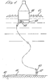
- FIG. 1 illustrates very diagrammatically an under-sea oil well terminal connected to a floating buoy by means of a flexible pipe embodying the present invention
- FIG. 1 of the drawings is shown, very diagrammatically, an under-sea oil terminal which includes a pipe 11 coming from a capped oil well (not shown) below the sea bed 10.
- the pipe 11 is connected by a pipe joint 12 to a long flexible pipe 13 (shown broken in the middle to illustrate considerable length).
- the upper end of the flexible pipe 13 is attached by a joint 14 to a tank 15 contained in a buoy 16 floating on the surface of the sea 17 located and maintained in position by any conventional means.
- the buoy 16 is shown diagrammatically and would, in practice, be a very large buoy adapted to form a terminal from which oil could be drawn into tankers and other ships. Alternatively, the pipe might connect to a ship or tanker directly.
- the oil below the sea bed is often at a very high pressure of the order of 27580 to 55160 x 10 3 Nm- 2 (4000/8000 Ib per sq. inch) or more and the flexible pipe 13 would be subjected not only to this high internal pressure but to constant flexures and movements due to sub-surface currents and wave movements. Consequently this pipe has to be able to stand up to considerable flexing and stresses in addition to the very high hoop stress and longitudinal stresses set up internally by the pressure from the well.
- the illustrated flexible pipe might equally be used for a gas well below the sea surface. It might be used not merely to extract oil but for gas re-injection into a sub-sea well and the water re-injection into a well to pressurise the gas remaining in it when the gas is to be extracted.
- One known kind of pipe has reinforcement in the form of individual strips of high tensile steel laid in helical fashion followed by a second layer of helical strips known as "tension tendons". These are designed to carry the end stress but problems arise when the pipe stretches and the helical strips shrink radially inwards which causes friction, heat and degradation and results in failure of the pipe at very high pressures.
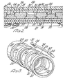
- These steel rings and keepers form the central core of the pipe wall.
- the rings contain the hoop stress and the end-thrust due to internal pressure is carried by the steel keeper bars and these keepers are applied in a staggered fashion ( Figure 7), so that each keeper traps 3 rings.
- These keepers are sized to carry the total end-thrust and to limit the movement of the pressure carrying rings sufficient that the pipe can be bent to a radius of 5.3 m with the extension (on the outer bend radius) shared uniformly over all pressure rings.
- the pipe is similar to the human spinal column, with limited flexibility - the vertebrae being the pressure rings and the tendons uniting the vertebrae, the keepers. Thus flexure does not incur friction.
- the tongue and groove joints of the pressure rings prevent lateral displacement of the rings (no "slipped discs").
- the remaining portions of the wall of the pipe as illustrated comprise an extruded elastomeric outer cover 36, which is fluid tight, and two layers of an elastomeric inner lining 37 and 38 supported by a stainless steel helically coiled core 39, or a corrugated core 39a ( Figure 9).
- the pipe shown in Figures 2 and 3 thus has a flexible, segmented, pressure-resistant layer.
- the steel rings 20 and 21 are spigoted together with clearances in such a way that they can move both axially and radially but the extent of movement is limited by the use of the keeper bars 24.
- the keeper bars 24 are staggered circumferentially around the pipe and are sprung on but allow small relative movement in an axial sense to occur and also limit the radial movements of the rings which can occur.
- the clearances 27 and 28 may for example be of the order of 0.8 mm in a 25 cm internal diameter pipe in which rings 20 may be of the order of 25 mm in length. This will allow the pipe to be bent to a radius of 5.3 m approximately. Being made of high tensile steel the rings 20 and 21 will accommodate and sustain the hoop stress developed by the high pressure of the oil or gas in the pipe.
- keepers 24, also being made of high tensile steel are designed to be thick enough and strong enough to withstand the end-wise or axial loading on the pipe, but this is not essential if alternative means are provided to accommodate end-wise stress as in the embodiment shown in Figures 11 to 17 described later.
- the rings 20 and 21 are preferably made by forging the rings from high tensile steel and then machining the surfaces to the required degree of accuracy to ensure that the small clearances between the rings are maintained.
- the rings might be cast to approximate shape and then machined to final shape, or precision cast.
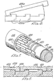
- FIG 4 is shown an alternative embodiment in which the rings 120 are all of the same cross sectional shape.
- the rings are designed so that they are non-symmetrical in the sense that there is a spigot 121 at one end of each ring and a corresponding recess or groove 122 at the other end of each ring.
- the rings are arranged with axial and radial gaps between them.
- Each ring 120 has a radial extension 123 which provides a pair of wedge like surfaces 124, 125 for engagement by corresponding wedge like surfaces 126 and 127 on keeper bars 128.
- the keeper bars embrace only two rings in this instance and are staggered circumferentially as illustrated in Figure 5.
- Figure 6 shows how a keeper bar is applied.
- three rings 120a (shown diagrammatically) are embraced by a single keeper bar 128.
- the rings are brought close together, closing up the gaps between them and then the bar 128a is sprung over the wedge surfaces at the ends of the bars. There is sufficient clearance to allow the rings limited freedom of axial movement but the keeper bars retain the rings within these limits.
- FIG 7 shows diagrammatically how a flexible pipe in accordance with this invention is built up.
- the stainless steel helically coiled core 39 provides support for the two elastomeric inner lining layers 38 and 37.
- the rings 120 (in this instance of the type shown in Figure 4) are slid onto the lining 37 so that their spigot ends interengage loosely.
- the keeper bars 128 are then applied, as described with reference to Figure 6 and are built up in the pattern shown in Figure 7 so that the keepers or keeper bars 128 are staggered circumferentially around the pipe.
- the assembly can then be completed by use of an extruded plastic cover 36. If required, in order to maintain the assembly in place while the plastic cover is extruded steel bands may be encircled round the keeper bars 128.
- the keeper bars may be provided, as shown in Figure 8 with recesses 130 which are arranged to align with each other so that a single steel band 129 can be arranged to encircle all of the keeper bars. This can be repeated at intervals as illustrated in Figure 8.
- the flanged end fitting 131 first receives a steel end ring 132 which has pressure tight '0' rings 133 of elastomeric material. Then a flexible steel band 134 is inserted. This band has a gap 135 to allow it to flex readily.
- the elastomeric liner 38 and stainless steel core 39 are then fed into the flanged end fitting 131 and an extension piece 136a is then welded at 137 to the flanged end fitting 131 to hold the core in place.
- a second end ring 138 again with 'O' ring seal 133a is then inserted.
- An appropriately dimensioned washer is then added and a steel plug 140 screwed in so as to tighten up the end assembly. This causes the member 134 to flex and grip the liners 37 and 38 firmly.
- the plug 140 includes a grub screw 141 to hold it in position.
- the plug 140 is formed with an end 142 similar to the ends of the rings 120 previously described.
- a series of rings 120 are then slid over the assembly and the keeper bars 24 are applied as previously described.
- the other end of the flexible pipe is completed with a similar fitting as shown in Figure 10.
- a flange fitting 145 with an integral flange 146.
- Similar end rings 132a and 138a are employed together with a flexible steel band 134a.
- a steel washer 139a is employed and a screwed-in plug 147.
- a series of inter-engaging rings 151 are used which are held together in groups of four by thin light-weight keepers 152.
- the rings 151 are sufficiently thick and are of sufficiently high tensile strength to withstand the hoop stress in the pipe but the keepers 152 are thin and flexible and would not normally be sufficiently strong to withstand the maximum end-wise stress.
- the keepers 152 may embrace four rings as shown in Figure 11, or as shown in Figure 12 only two rings, but they are staggered circumferentially as previously described. As seen in Figure 12 the rings 151 have inter-engaging spigot members 153 and recesses 154 and also have small axial and radial spacings as described in the previous embodiment.
- the cable includes an inner flexible liner 155 and a stainless steel spirally wound core 156 in addition to the outer polyamide extruded coating 157.
- the cable 153 is carried at its end by a steel cotter pin 158 with a bulbous end which is attached to the cable by means of a ferrule 159 which may be vacuum impregnated with epoxy resin.
- the cotter pin 158 is attached to a spider 160 and held fast by bolts 161.
- the spider is gripped in a flanged end member 162.
- Figure 11 by set screws 163.
- the position of the spider may be adjusted to vary the tension on the cable 153. This achieved by tightening up a nut 164.
- a gauge nut 165 is employed to check the tension. It should be noted that with this design it is not possible-for the pipe to be 'pigged' whereas with the embodiments shown in Figure 1 since there is a clearance down the central bore of the pipe it can be pigged (i.e. a cleaning device can be drawn through the pipe end-to-end down the central bore).
- the central tension cable can comprise a bundle of, for example, 788 16-gauge piano wires helically wound and bonded to the ferrules at each end.
- the cable can be subjected before installation to tensioning by means of a hydraulic stud tensioner.
- the end fittings for this embodiment of the flexible pipe are exactly as illustrated in Figures ⁇ 9 and 10.
- a number of spiders are arranged at intervals of 1 to 1 t meters all the way along the cable, the spiders being of the type shown in the drawings.
Landscapes
- Engineering & Computer Science (AREA)
- General Engineering & Computer Science (AREA)
- Mechanical Engineering (AREA)
- Mining & Mineral Resources (AREA)
- Geology (AREA)
- Life Sciences & Earth Sciences (AREA)
- Geochemistry & Mineralogy (AREA)
- Fluid Mechanics (AREA)
- Physics & Mathematics (AREA)
- General Life Sciences & Earth Sciences (AREA)
- Environmental & Geological Engineering (AREA)
- Rigid Pipes And Flexible Pipes (AREA)
- Earth Drilling (AREA)
- Superconductors And Manufacturing Methods Therefor (AREA)
- Glass Compositions (AREA)
- Joints That Cut Off Fluids, And Hose Joints (AREA)
- Pipe Accessories (AREA)
- Joints Allowing Movement (AREA)
- Supports For Pipes And Cables (AREA)
Claims (15)
Priority Applications (1)
| Application Number | Priority Date | Filing Date | Title |
|---|---|---|---|
| AT81303493T ATE9928T1 (de) | 1980-07-31 | 1981-07-30 | Flexibler schlauch. |
Applications Claiming Priority (2)
| Application Number | Priority Date | Filing Date | Title |
|---|---|---|---|
| GB8025015 | 1980-07-31 | ||
| GB8025015 | 1980-07-31 |
Publications (2)
| Publication Number | Publication Date |
|---|---|
| EP0045632A1 EP0045632A1 (fr) | 1982-02-10 |
| EP0045632B1 true EP0045632B1 (fr) | 1984-10-17 |
Family
ID=10515163
Family Applications (1)
| Application Number | Title | Priority Date | Filing Date |
|---|---|---|---|
| EP81303493A Expired EP0045632B1 (fr) | 1980-07-31 | 1981-07-30 | Tuyau flexible |
Country Status (14)
| Country | Link |
|---|---|
| US (1) | US4383554A (fr) |
| EP (1) | EP0045632B1 (fr) |
| JP (1) | JPS5740190A (fr) |
| KR (1) | KR830006618A (fr) |
| AT (1) | ATE9928T1 (fr) |
| AU (1) | AU539838B2 (fr) |
| CA (1) | CA1163212A (fr) |
| DE (1) | DE3166712D1 (fr) |
| EG (1) | EG15297A (fr) |
| ES (1) | ES503495A0 (fr) |
| HK (1) | HK33285A (fr) |
| MX (1) | MX152352A (fr) |
| NO (1) | NO812104L (fr) |
| SG (1) | SG14185G (fr) |
Families Citing this family (93)
| Publication number | Priority date | Publication date | Assignee | Title |
|---|---|---|---|---|
| US4556340A (en) * | 1983-08-15 | 1985-12-03 | Conoco Inc. | Method and apparatus for production of subsea hydrocarbons using a floating vessel |
| NO165612C (no) * | 1984-06-20 | 1991-03-06 | Furukawa Electric Co Ltd | Fleksibelt, sammensatt roer for transport av et hoeytemperaturfluid. |
| JPH034877Y2 (fr) * | 1986-02-04 | 1991-02-07 | ||
| JPS62180190A (ja) * | 1986-02-04 | 1987-08-07 | 工業技術院長 | フレキシブルホ−ス端部の補強構造 |
| GB8603553D0 (en) * | 1986-02-13 | 1986-03-19 | Btr Plc | Flexible elongate tubular article |
| FR2616858B1 (fr) * | 1987-06-18 | 1989-09-01 | Inst Francais Du Petrole | Element a raideur variable pour pied de colonne de transfert |
| JPH0540389Y2 (fr) * | 1987-06-30 | 1993-10-13 | ||
| FR2631097B1 (fr) * | 1988-05-09 | 1990-01-26 | Inst Francais Du Petrole | Tube flexible comportant un alliage d'aluminium |
| JPH0231992U (fr) * | 1988-08-24 | 1990-02-28 | ||
| FR2647524B1 (fr) * | 1989-05-23 | 1991-10-31 | Inst Francais Du Petrole | Conduite flexible comportant un materiau composite a matrice en alliage d'aluminium et procede de fabrication dudit materiau |
| US5261616A (en) * | 1992-02-19 | 1993-11-16 | The United States Of America As Represented By The Secretary Of The Navy | Multi-layered translated rib-stiffened composite hollow cylinder assembly |
| US5439323A (en) * | 1993-07-09 | 1995-08-08 | Westinghouse Electric Corporation | Rod and shell composite riser |
| US6164570A (en) * | 1994-11-14 | 2000-12-26 | Water Pik, Inc. | Self-supporting reconfigurable hose |
| US5997047A (en) * | 1996-02-28 | 1999-12-07 | Pimentel; Ralph | High-pressure flexible self-supportive piping assembly |
| US5730554A (en) * | 1996-03-22 | 1998-03-24 | Abb Vetco Gray Inc. | Articulated riser protector |
| US5865378A (en) * | 1997-01-10 | 1999-02-02 | Teledyne Industries, Inc. | Flexible shower arm assembly |
| USD440641S1 (en) | 1997-01-10 | 2001-04-17 | Water Pik, Inc. | Flexible shower arm |
| USD406636S (en) * | 1998-01-06 | 1999-03-09 | Teledyne Industries, Inc. | Flexible shower arm |
| DE19837497A1 (de) | 1998-08-13 | 2000-02-24 | Trinova Aeroquip Gmbh | Flexibler strangförmiger Hohlkörper |
| DE19837498A1 (de) | 1998-08-13 | 2000-02-24 | Trinova Aeroquip Gmbh | Flexibler strangförmiger Hohlkörper |
| JP3521405B2 (ja) * | 1998-08-13 | 2004-04-19 | エアロクイップ ツヴァイクニーデルラッシュング デア エアロクイップ−ビッカース インターナショナル ゲーエムベーハー | 屈曲可能なコード状中空体 |
| USD528631S1 (en) | 2000-12-12 | 2006-09-19 | Water Pik, Inc. | Pan head shower head |
| AU2002235211A1 (en) | 2000-12-12 | 2002-06-24 | Water Pik, Inc. | Shower head assembly |
| US6626210B2 (en) | 2001-01-12 | 2003-09-30 | Water Pik, Inc. | Flexible arm assembly |
| US6815026B2 (en) | 2002-11-07 | 2004-11-09 | Perry Philp | Helically-wound duct |
| GB2395539B (en) * | 2002-11-20 | 2005-08-17 | Coflexip | Umbilical |
| US7114666B2 (en) | 2002-12-10 | 2006-10-03 | Water Pik, Inc. | Dual massage shower head |
| US7533906B2 (en) | 2003-10-14 | 2009-05-19 | Water Pik, Inc. | Rotatable and pivotable connector |
| US8024822B2 (en) | 2004-06-14 | 2011-09-27 | Water Pik, Inc. | Articulating shower arm |
| USD527440S1 (en) | 2004-09-01 | 2006-08-29 | Water Pik, Inc. | Drenching shower head |
| US7740186B2 (en) | 2004-09-01 | 2010-06-22 | Water Pik, Inc. | Drenching shower head |
| USD529151S1 (en) | 2004-10-18 | 2006-09-26 | Water Pik, Inc. | Articulating shower arm |
| USD533253S1 (en) | 2004-11-03 | 2006-12-05 | Water Pik, Inc. | Elliptical shower head |
| US7905429B2 (en) | 2005-10-18 | 2011-03-15 | Water Pik, Inc. | Dispensing system and method for shower arm |
| EP2007483A2 (fr) | 2006-04-20 | 2008-12-31 | Water Pik, Inc. | Pomme de douche a pulverisation convergente |
| US20080083844A1 (en) | 2006-10-09 | 2008-04-10 | Water Pik, Inc. | Showerhead attachment assembly |
| US8020787B2 (en) | 2006-11-29 | 2011-09-20 | Water Pik, Inc. | Showerhead system |
| USD577793S1 (en) | 2006-11-29 | 2008-09-30 | Water Pik, Inc. | Showerhead assembly |
| USD577099S1 (en) | 2006-11-29 | 2008-09-16 | Water Pik, Inc. | Showerhead assembly |
| US7789326B2 (en) | 2006-12-29 | 2010-09-07 | Water Pik, Inc. | Handheld showerhead with mode control and method of selecting a handheld showerhead mode |
| US7770822B2 (en) | 2006-12-28 | 2010-08-10 | Water Pik, Inc. | Hand shower with an extendable handle |
| US8794543B2 (en) | 2006-12-28 | 2014-08-05 | Water Pik, Inc. | Low-speed pulsating showerhead |
| US8366024B2 (en) | 2006-12-28 | 2013-02-05 | Water Pik, Inc. | Low speed pulsating showerhead |
| US8789218B2 (en) | 2007-05-04 | 2014-07-29 | Water Pik, Inc. | Molded arm for showerheads and method of making same |
| USD580513S1 (en) | 2007-12-20 | 2008-11-11 | Water Pik, Inc. | Hand shower |
| USD580012S1 (en) | 2007-12-20 | 2008-11-04 | Water Pik, Inc. | Showerhead |
| USD592278S1 (en) | 2007-12-20 | 2009-05-12 | Water Pik, Inc. | Showerhead |
| USD581014S1 (en) | 2007-12-20 | 2008-11-18 | Water Pik, Inc. | Hand shower |
| USD603935S1 (en) | 2007-12-20 | 2009-11-10 | Water Pik, Inc. | Hand shower |
| USD590048S1 (en) | 2007-12-20 | 2009-04-07 | Water Pik, Inc. | Hand shower |
| USD605731S1 (en) | 2007-12-26 | 2009-12-08 | Water Pik, Inc. | Bracket for hand shower |
| USD624156S1 (en) | 2008-04-30 | 2010-09-21 | Water Pik, Inc. | Pivot ball attachment |
| USD618766S1 (en) | 2008-05-01 | 2010-06-29 | Water Pik, Inc. | Showerhead arm |
| US8348181B2 (en) | 2008-09-15 | 2013-01-08 | Water Pik, Inc. | Shower assembly with radial mode changer |
| USD600777S1 (en) | 2008-09-29 | 2009-09-22 | Water Pik, Inc. | Showerhead assembly |
| USD606623S1 (en) | 2008-09-29 | 2009-12-22 | Water Pik, Inc. | Hand shower |
| USD616061S1 (en) | 2008-09-29 | 2010-05-18 | Water Pik, Inc. | Showerhead assembly |
| US8444185B2 (en) * | 2009-06-24 | 2013-05-21 | Parker-Hanninfin Corporation | Flexible extrusion resistant ring seal assembly |
| USD625776S1 (en) | 2009-10-05 | 2010-10-19 | Water Pik, Inc. | Showerhead |
| US8152949B2 (en) * | 2009-11-20 | 2012-04-10 | Lockheed Martin Corporation | Pultruded arc-segmented pipe |
| GB2479552B (en) * | 2010-04-14 | 2015-07-08 | Aker Subsea Ltd | Subsea wellhead providing controlled access to a casing annulus |
| US8616470B2 (en) | 2010-08-25 | 2013-12-31 | Water Pik, Inc. | Mode control valve in showerhead connector |
| US8820412B2 (en) * | 2011-09-16 | 2014-09-02 | Chevron U.S.A. Inc. | Methods, systems and apparatus for circulating fluid within the annulus of a flexible pipe riser |
| US9046201B1 (en) * | 2012-01-04 | 2015-06-02 | Schieffer Co. International L.C. | High pressure highly flexible, stable in length, thermoplastic hose and method of making the same |
| DE202012000063U1 (de) | 2012-01-04 | 2013-04-05 | Linde Engineering Gmbh | Kabelfixiervorrichtung zum Fixieren zumindest eines Kabels sowie Klemmeinrichtung für eine solche |
| USD678467S1 (en) | 2012-01-27 | 2013-03-19 | Water Pik, Inc. | Ring-shaped handheld showerhead |
| USD678463S1 (en) | 2012-01-27 | 2013-03-19 | Water Pik, Inc. | Ring-shaped wall mount showerhead |
| CA2898716C (fr) | 2012-06-22 | 2020-02-11 | Water Pik, Inc. | Support pour pomme de douche avec regulation de debit integree |
| USD692111S1 (en) | 2012-10-11 | 2013-10-22 | Water Pik, Inc. | Mounting bracket for water flosser |
| USD711505S1 (en) | 2013-05-20 | 2014-08-19 | Water Pik, Inc. | Shower arm |
| USD711506S1 (en) | 2013-05-20 | 2014-08-19 | Water Pik, Inc. | Showerhead with arm |
| WO2014201420A1 (fr) | 2013-06-13 | 2014-12-18 | Water Pik, Inc. | Pomme de douche ayant un mécanisme d'obturation entraîné par turbine |
| NO336257B1 (no) * | 2013-09-10 | 2015-07-06 | Safehose Holding As | Anordning ved dobbel slangekonstruksjon. |
| USD744066S1 (en) | 2014-06-13 | 2015-11-24 | Water Pik, Inc. | Wall mount showerhead |
| USD744612S1 (en) | 2014-06-13 | 2015-12-01 | Water Pik, Inc. | Handheld showerhead |
| USD744064S1 (en) | 2014-06-13 | 2015-11-24 | Water Pik, Inc. | Handheld showerhead |
| USD744065S1 (en) | 2014-06-13 | 2015-11-24 | Water Pik, Inc. | Handheld showerhead |
| USD744614S1 (en) | 2014-06-13 | 2015-12-01 | Water Pik, Inc. | Wall mount showerhead |
| USD744611S1 (en) | 2014-06-13 | 2015-12-01 | Water Pik, Inc. | Handheld showerhead |
| USD745111S1 (en) | 2014-06-13 | 2015-12-08 | Water Pik, Inc. | Wall mount showerhead |
| US10730061B2 (en) | 2014-10-03 | 2020-08-04 | Water Pik, Inc. | Automatically locking shower arm joint |
| EP3411155B1 (fr) | 2016-02-01 | 2020-03-25 | Water Pik, Inc. | Lance de pulvérisation portative pour animaux domestiques |
| USD803981S1 (en) | 2016-02-01 | 2017-11-28 | Water Pik, Inc. | Handheld spray nozzle |
| USD970684S1 (en) | 2016-04-15 | 2022-11-22 | Water Pik, Inc. | Showerhead |
| US10265710B2 (en) | 2016-04-15 | 2019-04-23 | Water Pik, Inc. | Showerhead with dual oscillating massage |
| US11066913B2 (en) | 2016-05-01 | 2021-07-20 | Cameron International Corporation | Flexible fracturing line with removable liner |
| EP3669997B1 (fr) | 2016-09-08 | 2022-10-12 | Water Pik, Inc. | Ensemble de pause pour pommes de douche |
| USD843549S1 (en) | 2017-07-19 | 2019-03-19 | Water Pik, Inc. | Handheld spray nozzle |
| USD872227S1 (en) | 2018-04-20 | 2020-01-07 | Water Pik, Inc. | Handheld spray device |
| DE102018112488A1 (de) * | 2018-05-24 | 2019-11-28 | Mann+Hummel Gmbh | Rohrbauteil |
| US11015413B2 (en) | 2018-10-31 | 2021-05-25 | Cameron International Corporation | Fracturing system with fluid conduit having communication line |
| US11319757B2 (en) | 2019-12-26 | 2022-05-03 | Cameron International Corporation | Flexible fracturing fluid delivery conduit quick connectors |
| US12612986B2 (en) | 2021-06-01 | 2026-04-28 | Cameron International Corporation | Quick conduit connection system |
Family Cites Families (8)
| Publication number | Priority date | Publication date | Assignee | Title |
|---|---|---|---|---|
| GB189320860A (en) * | 1893-11-03 | 1894-09-08 | Joseph Thompson | Improvements connected with Armoured Flexible Hose. |
| US2079598A (en) * | 1933-01-19 | 1937-05-11 | Metal Hose & Tubing Co Inc | Gasoline hose |
| GB573011A (en) * | 1944-01-31 | 1945-11-01 | Frank Edward Swain | Improvements relating to flexible pipes |
| GB863360A (en) * | 1956-06-20 | 1961-03-22 | Btr Industries Ltd | Improvements in flexible pipes |
| US3538956A (en) * | 1968-12-17 | 1970-11-10 | Ppg Industries Inc | Flexible duct with interlocking-type coupling |
| FR2217621B1 (fr) * | 1973-02-15 | 1976-05-14 | Inst Francais Du Petrole | |
| FR2260740A2 (en) * | 1974-02-07 | 1975-09-05 | Inst Francais Du Petrole | Armoured sleeving for conduits - has interconnected rings with shoulder extensions to prevent disconnection |
| US4233820A (en) * | 1979-02-14 | 1980-11-18 | W B Driver | Flexible drill pipe |
-
1981
- 1981-06-19 NO NO812104A patent/NO812104L/no unknown
- 1981-06-19 CA CA000380224A patent/CA1163212A/fr not_active Expired
- 1981-06-29 ES ES503495A patent/ES503495A0/es active Granted
- 1981-07-02 AU AU72507/81A patent/AU539838B2/en not_active Ceased
- 1981-07-14 US US06/282,994 patent/US4383554A/en not_active Expired - Fee Related
- 1981-07-15 JP JP56109528A patent/JPS5740190A/ja active Pending
- 1981-07-30 DE DE8181303493T patent/DE3166712D1/de not_active Expired
- 1981-07-30 EP EP81303493A patent/EP0045632B1/fr not_active Expired
- 1981-07-30 KR KR1019810002770A patent/KR830006618A/ko active Pending
- 1981-07-30 AT AT81303493T patent/ATE9928T1/de active
- 1981-07-31 MX MX188556A patent/MX152352A/es unknown
- 1981-08-04 EG EG81443A patent/EG15297A/xx active
-
1985
- 1985-02-22 SG SG141/85A patent/SG14185G/en unknown
- 1985-05-02 HK HK332/85A patent/HK33285A/xx unknown
Also Published As
| Publication number | Publication date |
|---|---|
| SG14185G (en) | 1985-08-16 |
| ES8301529A1 (es) | 1982-12-01 |
| KR830006618A (ko) | 1983-09-28 |
| EG15297A (en) | 1986-03-31 |
| EP0045632A1 (fr) | 1982-02-10 |
| HK33285A (en) | 1985-05-10 |
| DE3166712D1 (en) | 1984-11-22 |
| MX152352A (es) | 1985-07-02 |
| US4383554A (en) | 1983-05-17 |
| AU539838B2 (en) | 1984-10-18 |
| AU7250781A (en) | 1982-02-04 |
| JPS5740190A (en) | 1982-03-05 |
| ATE9928T1 (de) | 1984-11-15 |
| ES503495A0 (es) | 1982-12-01 |
| CA1163212A (fr) | 1984-03-06 |
| NO812104L (no) | 1982-02-01 |
Similar Documents
| Publication | Publication Date | Title |
|---|---|---|
| EP0045632B1 (fr) | Tuyau flexible | |
| US6691743B2 (en) | Flexible pipe with wire or strip winding for maintaining armours | |
| EP0978677B1 (fr) | Ensemble raccord de tuyau composite renforcé par fibres et soumis à des pressions élevées | |
| US10451206B2 (en) | Connection end-piece of a flexible pipe for transporting fluid and associated method | |
| AU2007259104B2 (en) | Radius control | |
| US8276620B2 (en) | Flexible pipe for offshore and other applications | |
| US6053213A (en) | Flexible pipe for great depths | |
| US5909007A (en) | Bending restrictor | |
| US20230323984A1 (en) | Mounting and cathodic protection | |
| JPH0151717B2 (fr) | ||
| US20190017641A1 (en) | Connection tip for a flexible line, and associated flexible line and mounting method | |
| GB2081417A (en) | Flexible pipe | |
| US11506308B2 (en) | Clamping device for flexible pipe for subsea applications, and related method | |
| DK1154184T4 (en) | Flexible tubes of sheath of wire or strip to the support of the reinforcement. | |
| WO2025011773A1 (fr) | Support de couche | |
| US20250180149A1 (en) | Gripping body | |
| WO2025021322A1 (fr) | Tuyau flexible et raccord |
Legal Events
| Date | Code | Title | Description |
|---|---|---|---|
| PUAI | Public reference made under article 153(3) epc to a published international application that has entered the european phase |
Free format text: ORIGINAL CODE: 0009012 |
|
| AK | Designated contracting states |
Designated state(s): AT BE DE FR IT NL SE |
|
| 17P | Request for examination filed |
Effective date: 19820329 |
|
| ITF | It: translation for a ep patent filed | ||
| GRAA | (expected) grant |
Free format text: ORIGINAL CODE: 0009210 |
|
| AK | Designated contracting states |
Designated state(s): AT BE DE FR IT NL SE |
|
| REF | Corresponds to: |
Ref document number: 9928 Country of ref document: AT Date of ref document: 19841115 Kind code of ref document: T |
|
| REF | Corresponds to: |
Ref document number: 3166712 Country of ref document: DE Date of ref document: 19841122 |
|
| ET | Fr: translation filed | ||
| PGFP | Annual fee paid to national office [announced via postgrant information from national office to epo] |
Ref country code: AT Payment date: 19850614 Year of fee payment: 5 |
|
| PGFP | Annual fee paid to national office [announced via postgrant information from national office to epo] |
Ref country code: NL Payment date: 19850731 Year of fee payment: 5 |
|
| PLBE | No opposition filed within time limit |
Free format text: ORIGINAL CODE: 0009261 |
|
| STAA | Information on the status of an ep patent application or granted ep patent |
Free format text: STATUS: NO OPPOSITION FILED WITHIN TIME LIMIT |
|
| 26N | No opposition filed | ||
| PG25 | Lapsed in a contracting state [announced via postgrant information from national office to epo] |
Ref country code: AT Effective date: 19860730 |
|
| PG25 | Lapsed in a contracting state [announced via postgrant information from national office to epo] |
Ref country code: SE Effective date: 19860731 Ref country code: BE Effective date: 19860731 |
|
| BERE | Be: lapsed |
Owner name: MOBIL OIL CORP. Effective date: 19860731 |
|
| PG25 | Lapsed in a contracting state [announced via postgrant information from national office to epo] |
Ref country code: NL Effective date: 19870201 |
|
| NLV4 | Nl: lapsed or anulled due to non-payment of the annual fee | ||
| PG25 | Lapsed in a contracting state [announced via postgrant information from national office to epo] |
Ref country code: FR Free format text: LAPSE BECAUSE OF NON-PAYMENT OF DUE FEES Effective date: 19870331 |
|
| REG | Reference to a national code |
Ref country code: FR Ref legal event code: ST |
|
| PG25 | Lapsed in a contracting state [announced via postgrant information from national office to epo] |
Ref country code: DE Effective date: 19870701 |
|
| EUG | Se: european patent has lapsed |
Ref document number: 81303493.1 Effective date: 19870609 |