EP0045724A1 - Kupplung mit einem Verriegelungsring - Google Patents
Kupplung mit einem Verriegelungsring Download PDFInfo
- Publication number
- EP0045724A1 EP0045724A1 EP81830131A EP81830131A EP0045724A1 EP 0045724 A1 EP0045724 A1 EP 0045724A1 EP 81830131 A EP81830131 A EP 81830131A EP 81830131 A EP81830131 A EP 81830131A EP 0045724 A1 EP0045724 A1 EP 0045724A1
- Authority
- EP
- European Patent Office
- Prior art keywords
- joint
- eccentric cam
- elastic strip
- strip
- cam means
- Prior art date
- Legal status (The legal status is an assumption and is not a legal conclusion. Google has not performed a legal analysis and makes no representation as to the accuracy of the status listed.)
- Granted
Links
- 238000012856 packing Methods 0.000 claims abstract description 4
- 230000008878 coupling Effects 0.000 description 5
- 238000010168 coupling process Methods 0.000 description 5
- 238000005859 coupling reaction Methods 0.000 description 5
- 241000251729 Elasmobranchii Species 0.000 description 1
- 101100400378 Mus musculus Marveld2 gene Proteins 0.000 description 1
- 235000008331 Pinus X rigitaeda Nutrition 0.000 description 1
- 235000011613 Pinus brutia Nutrition 0.000 description 1
- 241000018646 Pinus brutia Species 0.000 description 1
- 230000004913 activation Effects 0.000 description 1
- 238000010276 construction Methods 0.000 description 1
- 230000008602 contraction Effects 0.000 description 1
- 238000006073 displacement reaction Methods 0.000 description 1
- 230000000694 effects Effects 0.000 description 1
- 230000002349 favourable effect Effects 0.000 description 1
- 238000003780 insertion Methods 0.000 description 1
- 230000037431 insertion Effects 0.000 description 1
- 239000003129 oil well Substances 0.000 description 1
- 230000001105 regulatory effect Effects 0.000 description 1
- 230000000717 retained effect Effects 0.000 description 1
- 238000007789 sealing Methods 0.000 description 1
- 239000000126 substance Substances 0.000 description 1
- 239000011800 void material Substances 0.000 description 1
Images

Classifications
-
- F—MECHANICAL ENGINEERING; LIGHTING; HEATING; WEAPONS; BLASTING
- F16—ENGINEERING ELEMENTS AND UNITS; GENERAL MEASURES FOR PRODUCING AND MAINTAINING EFFECTIVE FUNCTIONING OF MACHINES OR INSTALLATIONS; THERMAL INSULATION IN GENERAL
- F16L—PIPES; JOINTS OR FITTINGS FOR PIPES; SUPPORTS FOR PIPES, CABLES OR PROTECTIVE TUBING; MEANS FOR THERMAL INSULATION IN GENERAL
- F16L25/00—Construction or details of pipe joints not provided for in, or of interest apart from, groups F16L13/00 - F16L23/00
-
- F—MECHANICAL ENGINEERING; LIGHTING; HEATING; WEAPONS; BLASTING
- F16—ENGINEERING ELEMENTS AND UNITS; GENERAL MEASURES FOR PRODUCING AND MAINTAINING EFFECTIVE FUNCTIONING OF MACHINES OR INSTALLATIONS; THERMAL INSULATION IN GENERAL
- F16B—DEVICES FOR FASTENING OR SECURING CONSTRUCTIONAL ELEMENTS OR MACHINE PARTS TOGETHER, e.g. NAILS, BOLTS, CIRCLIPS, CLAMPS, CLIPS OR WEDGES; JOINTS OR JOINTING
- F16B21/00—Means for preventing relative axial movement of a pin, spigot, shaft or the like and a member surrounding it; Stud-and-socket releasable fastenings
- F16B21/10—Means for preventing relative axial movement of a pin, spigot, shaft or the like and a member surrounding it; Stud-and-socket releasable fastenings by separate parts
- F16B21/16—Means for preventing relative axial movement of a pin, spigot, shaft or the like and a member surrounding it; Stud-and-socket releasable fastenings by separate parts with grooves or notches in the pin or shaft
-
- F—MECHANICAL ENGINEERING; LIGHTING; HEATING; WEAPONS; BLASTING
- F16—ENGINEERING ELEMENTS AND UNITS; GENERAL MEASURES FOR PRODUCING AND MAINTAINING EFFECTIVE FUNCTIONING OF MACHINES OR INSTALLATIONS; THERMAL INSULATION IN GENERAL
- F16J—PISTONS; CYLINDERS; SEALINGS
- F16J13/00—Covers or similar closure members for pressure vessels in general
- F16J13/02—Detachable closure members; Means for tightening closures
- F16J13/08—Detachable closure members; Means for tightening closures attached by one or more members actuated to project behind a part or parts of the frame
-
- F—MECHANICAL ENGINEERING; LIGHTING; HEATING; WEAPONS; BLASTING
- F16—ENGINEERING ELEMENTS AND UNITS; GENERAL MEASURES FOR PRODUCING AND MAINTAINING EFFECTIVE FUNCTIONING OF MACHINES OR INSTALLATIONS; THERMAL INSULATION IN GENERAL
- F16L—PIPES; JOINTS OR FITTINGS FOR PIPES; SUPPORTS FOR PIPES, CABLES OR PROTECTIVE TUBING; MEANS FOR THERMAL INSULATION IN GENERAL
- F16L37/00—Couplings of the quick-acting type
- F16L37/08—Couplings of the quick-acting type in which the connection between abutting or axially overlapping ends is maintained by locking members
- F16L37/12—Couplings of the quick-acting type in which the connection between abutting or axially overlapping ends is maintained by locking members using hooks, pawls, or other movable or insertable locking members
Definitions
- This invention concerns a joint with a clamping annular strip suitable for locking tubular structures together axially and torsionally.
- Said tubular structures can advantageously be hollow cylinders, parts constituing sleeves or other like or similar elements such as, for instance, piling tubes for foundations., tubes to obtain sample cores, etc. whereby a hydraulic seal is required in the joint and an external surface substantially void of projections and protrusions.
- the invention referrs to a joint with clamping strip suitable for use in locking tubular structures together axially and torsionally and for being employed often in coupling together and uncoupling axially parts of said tubular structures, for example,when foundation holes have to be excavated or sample cores of the terrain or other substances. have to be taken.
- GB 730.339 teaches that the split ring whose ends are . normally apart is contracted by means of a series of locking screws mounted in radially extending threaded holes in the wall of the external of a socket pipe for engaging the split ring at intervals around its periphery and forcing it out for the groove in the outer pipe and into the groove of the inner pipe to lock the two pipes together.
- a split ring pipe joint with similar locking screws is proposed in GB 1,107,273 with the addition of a gasket plastically deformed in the circumferential chamber by the pressure of the split ring and a series of windows formed in the wall of the external pipe in the spaces intervening with the locking screw locations through which the conditions of the. split ringmayhe observed and manipulated during its insertion or removal.
- An analoguous joint is provided in GB 1,487,948 in which the locking screw means include a first part threadedly engaged in a radial bore in the outer pipe and a second part is fixed relative to the split ring whereby the first and the second parts are coupled by a lost motion coupling.
- This arrangement is obviously intended to keep the split ring always coupled to the outer pipe.
- US 3,606,393 provides a similar pipe connector wherein the lock screws are housed in boxes projecting outwardly from the external wall of the outer pipe, the split ring being centralized by spring-loaded centralizer pins arranged cir-. cumferentially.
- GB 1,174,738 proposes a split ring pipe joint in which an expanded contractible split ring is employed to form the latch.
- FR-A-1,466,116 describes a split ring joint whereby the ends . of the ring are moved relative to each other by an external . tool basically similar to that described in GB 1,174,738 . with the difference that thistoolispermanently anchored to
- US 2,901,269 proposes a split-ring joint with lock means in the form of an annular plug arranged between the ends of the split which, upon rotation, is capable of separating the ends thus expanding the contractible split ring into an inoperative position.
- the plug means must be retained by a suitable cover plate to hold it in its own housing.
- US 2,877,732 proposes a joint of the split ring type for connecting torpedoe sections in which the ends of the split ring are brought together and separated by a turnbuckle
- This joint requires a fairly large housing space for the turn buckle that must also be sufficient to receive the head of the wrench that has to turn therein.
- the invention therefore has the purpose of obtaining an improved split ring joint which overcomes the aforesaid drawbacks and at the same time provides an internal coupling which can be made quickly and gives a safe hydraulic seal and balanced connection between the components of the tubular structure.
- One purpose of the invention is to obtain a joint which enables a quick axial and torsional coupling to be made between hollow cylindrical structures.
- Another purpose is to obtain an annular strip joint with simple and reliable means for expanding and contracting said strip whereby said means can be actuated externally and occupy a relatively small housing that need not be externally sealed.
- the invention is embodied in a clamping strip joint for tubular structures such as, for instance, joints. for piping for lining purposes, whereby the end part of one. structure is circumferentially superimposed on the end part. of the other structure and there is at least one circumfer-. ential chamber formed by grooves cut in both the superimposed zones, and whereby axial tooth elements are present on one structure and cooperate with substantially counterpart recesses in the other structures to be connected, and whereby there
- an eccentric cam means is provided at each extremity of said auxiliary strip section which is snugly housed inside said . circumferential chamber whereby each eccentric cam means engages a respective recess means provided at each end of said elastic strip.
- one. extremity of said auxiliary strip section is integral to one end of said elastic strip while the other extremity of said. auxiliary strip section is provided with said eccentric cam. means which cooperates with a corresponding recess means provided at the other end of said elastic strip.
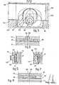
- Fig. 1 shows two hollow cylindrical parts or tubular structures 10 and 11 suitable for being connected axially together and. torsionally owing to the effect of the possible superimposition of the two superimposable end zones 110-111.
- Each cylindrical part or tubular structure 10-11 bears circumferentially, on the superimposable end parts 110-111 able to be coupled together, axial tooth elements 12-13 respectively which cooperate with the substantially counterpart spaces 15-14 respectively present on the other superimposable end part 111-110.
- said auxiliary strip section 19 consists of an arc section, having a smaller thickness than that of the elastic strip 16, snugly fitted into the circumferential chamber 25, although it may. also be fixed therein.
- the eccentric cam means 23 which each consists of an eccentric cam 27 are provided rotatingly at each extremity of said auxiliary strip section 19 in such a way as to project radially outwards therefrom.
- Said eccentric cam 27 cooperates with a corresponding recess means 123 curved out at each 116-216 of the elastic strip 16 which recess means consists of a semi-circular cut-out whose internal surface is engageable by the respective eccentric cam 27.
- Figure 3 shows an alternative embodiment of the invention in which said auxiliary strip section 19 is snugly housed in said circumferential chamber 25 and is integral to one end 216 of said elastic strip 16 while the other extremity of said auxiliary strip section 19 is provided with said eccentric cam means 23 which cooperates ina corresponding recess means 123 formed at the other end 116 of said elastic strip 16.
- Said eccentric cams 27 are contained together with the auxiliary strip 19 in an an appropriate seating inside the circumfer-. ential chamber 25.
- Said eccentric cam means 23 are accessible from outside through a correspondipg window 125 provided in the outer surface of the outer tubular structure 10.
- the cylindrical part II This enables the cylindrical part II to be inserted and to slide until its teeth 13 and spaces 15 are fully gripped and engaed with the opposed counterpart spaces 14 and opposed counterpart teeth 12 of the cylindrical part 10.
- the groove 17 having an annular shape and being machined on the outside of the cylindrical part II is face to face with the aforesaid inner groove 18 which contains the elastic strip 16.
- the two facing grooves 17 and 18 make one single and circumferential chamber 25 able to permit movements to expand or contract the elastic strip 16 radially and at least partially.
- the depth of the grooves 17 and 18 will be such that during. the closure phase the elastic strip 16 has to be contained in the respective groove, for instance 18,whereas during the clamping phase said strip will protrude from the clamping groove, for instance from 17.
- Safety means which may consist of one or more locking pins 22, enable the elastic strip 16 to be clamped within-the circumferential chamber 25.
- annular sealing packings 20 inserted into suitable seatings, are placed between the two cylindrical parts 10 - and 11 so as to create a hermetic seal in the connection made between said parts 10 and 11.
- Fig. 3 shows a section of a particular lay-out of a system for tensioning the joint with strip 16 according to the alterna tive embodiment.
- the eccentric cam 27, the position of which in our example can be regulated from the outside by means of suitable adjusting means, for instance with a socket spanner acting in the appropriate socket 26 as said before, can be rotated in two opposite directions, thus taking up the two positions shown with dashes in Fig. 3 and substantially lying at 180° for each other in the example shown.
- the. eccentric cam means 23 pushes the elastic strip 16 into the. annular groove 18 with its cam 27.
- said elastic strip 16 enters. wholly into said groove 18 only if, as in the example shown, the other eccentric cam 27 (Fig. 2) has also been rotated into a position which is the counterpart of the first cam 27.
- Figs. 4 and 5 respectively show a section of a detail of the position of the eccentric cam or cams 27 with the elastic strip 16 in the inoperative joint position and a section of a detail of the clamping with the pin 22, here too the elastic strip 16 bein in the inoperative joint position.
- Fig. 5 shows the locking pin partially withdrawn from the annular chamber 25 so as to enable the elastic strip 16 to enter wholly within the groove 18 in order possibly to be able to separate the two cylindrical parts 10 and 11.
- Fig. 6 shows a section of a detail of the position of the eccentric 27 with the elastic strin 16 in the operative joint position; in this position the eccentric cam 27 is rotated by 180° as compared to its position in the disactivated joint (Fig. 4).
- Fig. 7 shows a section of a detail of the locking pin 22 inserted into the possibly circumferential chamber 25 so as. to secure the elastic strp 16 in the operative joint position.
- the elastic strip 16 adheres at least partially to the inner surfaces of the annular groove 17 and perhaps to part of the surfaces of the annular groove 18.
- Figs. 5 and 7 together show the radial sliding. of the elastic strip 16 inside the chamber 25 so as to lie . respectively in one orthe other of the two positions with the joint inoperative or operative.
- Safety means in the specific example shown as locking pins 22,enable the axial fixture of the tubular parts 10 and 11 to be further ensured.
Landscapes
- Engineering & Computer Science (AREA)
- General Engineering & Computer Science (AREA)
- Mechanical Engineering (AREA)
- Quick-Acting Or Multi-Walled Pipe Joints (AREA)
Applications Claiming Priority (2)
| Application Number | Priority Date | Filing Date | Title |
|---|---|---|---|
| IT83418/80A IT1154734B (it) | 1980-07-31 | 1980-07-31 | Giunto a fascia |
| IT8341880 | 1980-07-31 |
Publications (2)
| Publication Number | Publication Date |
|---|---|
| EP0045724A1 true EP0045724A1 (de) | 1982-02-10 |
| EP0045724B1 EP0045724B1 (de) | 1984-09-12 |
Family
ID=11321591
Family Applications (1)
| Application Number | Title | Priority Date | Filing Date |
|---|---|---|---|
| EP81830131A Expired EP0045724B1 (de) | 1980-07-31 | 1981-07-27 | Kupplung mit einem Verriegelungsring |
Country Status (3)
| Country | Link |
|---|---|
| EP (1) | EP0045724B1 (de) |
| DE (1) | DE3166031D1 (de) |
| IT (1) | IT1154734B (de) |
Cited By (7)
| Publication number | Priority date | Publication date | Assignee | Title |
|---|---|---|---|---|
| US4792320A (en) * | 1985-09-18 | 1988-12-20 | A. O. Smith Corporation | Composite tubular structure |
| US4821818A (en) * | 1988-02-01 | 1989-04-18 | Micro Specialties Co., Inc. | Tube auger sections |
| US4853060A (en) * | 1987-07-17 | 1989-08-01 | A. O. Smith Corporation | Method of forming a composite tubular structure |
| US5269572A (en) * | 1992-08-28 | 1993-12-14 | Gold Star Manufacturing, Inc. | Apparatus and method for coupling elongated members |
| EP0634561A1 (de) * | 1993-07-16 | 1995-01-18 | Halliburton Company | Sandfilter zur Verwendung in Bohrlöchern |
| US5714062A (en) * | 1993-10-01 | 1998-02-03 | Water Pollution Control Corporation | Diffuser conduit joint |
| CN109611033A (zh) * | 2018-12-31 | 2019-04-12 | 大庆市华禹石油机械制造有限公司 | 用于石油工程中的油管 |
Citations (1)
| Publication number | Priority date | Publication date | Assignee | Title |
|---|---|---|---|---|
| US2901269A (en) * | 1957-01-31 | 1959-08-25 | Mcdowell Mfg Co | Split ring coupling |
-
1980
- 1980-07-31 IT IT83418/80A patent/IT1154734B/it active
-
1981
- 1981-07-27 DE DE8181830131T patent/DE3166031D1/de not_active Expired
- 1981-07-27 EP EP81830131A patent/EP0045724B1/de not_active Expired
Patent Citations (1)
| Publication number | Priority date | Publication date | Assignee | Title |
|---|---|---|---|---|
| US2901269A (en) * | 1957-01-31 | 1959-08-25 | Mcdowell Mfg Co | Split ring coupling |
Cited By (7)
| Publication number | Priority date | Publication date | Assignee | Title |
|---|---|---|---|---|
| US4792320A (en) * | 1985-09-18 | 1988-12-20 | A. O. Smith Corporation | Composite tubular structure |
| US4853060A (en) * | 1987-07-17 | 1989-08-01 | A. O. Smith Corporation | Method of forming a composite tubular structure |
| US4821818A (en) * | 1988-02-01 | 1989-04-18 | Micro Specialties Co., Inc. | Tube auger sections |
| US5269572A (en) * | 1992-08-28 | 1993-12-14 | Gold Star Manufacturing, Inc. | Apparatus and method for coupling elongated members |
| EP0634561A1 (de) * | 1993-07-16 | 1995-01-18 | Halliburton Company | Sandfilter zur Verwendung in Bohrlöchern |
| US5714062A (en) * | 1993-10-01 | 1998-02-03 | Water Pollution Control Corporation | Diffuser conduit joint |
| CN109611033A (zh) * | 2018-12-31 | 2019-04-12 | 大庆市华禹石油机械制造有限公司 | 用于石油工程中的油管 |
Also Published As
| Publication number | Publication date |
|---|---|
| DE3166031D1 (en) | 1984-10-18 |
| IT1154734B (it) | 1987-01-21 |
| IT8083418A0 (it) | 1980-07-31 |
| EP0045724B1 (de) | 1984-09-12 |
Similar Documents
| Publication | Publication Date | Title |
|---|---|---|
| CA1039771A (en) | Device for a coupling unit having connectable and disconnectable parts | |
| US5697135A (en) | Press tool | |
| US5387017A (en) | Coupling for attachment to the end of a pipe for securement to the pipe or for joining pipes together | |
| CA1207658A (en) | Marine riser coupling assembly | |
| US5934854A (en) | Ring fastener, apparatus for installing same, and installation method for the ring fastener | |
| US4050722A (en) | Joint for conduit | |
| GB1174738A (en) | Improvements in or relating to Tool Joints for Pipe | |
| GB1487948A (en) | Pipe connectors | |
| EP0045724A1 (de) | Kupplung mit einem Verriegelungsring | |
| US4223925A (en) | Hot tap machine | |
| US4052091A (en) | Coupling device | |
| BR0215367B1 (pt) | conexão de extremidade para tubulações e método para a sua fabricação. | |
| US6905148B2 (en) | Connector for securing conduits | |
| US4771678A (en) | Piston locking device for double acting hydraulic cylinder | |
| GB2339872A (en) | A connector for use in oilfield applications | |
| BR112017024670B1 (pt) | Conexão de tubo para conectar de forma vedante primeiro e segundo tubos, conexão de tubo para conectar de forma vedante um bloco usinado e um tubo, e método para ligar de forma vedante primeiro e segundo tubos ou um bloco usinado e um tubo por meio de uma conexão de tubo | |
| JPS5858549B2 (ja) | 金属導管のためのパイプジヨイント | |
| KR20140043298A (ko) | 파이프 커넥터 | |
| EP0200339B1 (de) | Rohrkupplungen | |
| RU2324101C2 (ru) | Муфта трубопровода | |
| US3600011A (en) | Joint utilizing wedge-shaped rectangular locking shafts | |
| JP2004003667A (ja) | 固着リング組付装置及びその方法 | |
| US4395060A (en) | Portable, reusable pipe coupling | |
| JPS62237193A (ja) | 管接合装置 | |
| AU2015208185B2 (en) | Downhole packer and associated methods |
Legal Events
| Date | Code | Title | Description |
|---|---|---|---|
| PUAI | Public reference made under article 153(3) epc to a published international application that has entered the european phase |
Free format text: ORIGINAL CODE: 0009012 |
|
| AK | Designated contracting states |
Designated state(s): BE CH DE FR GB |
|
| 17P | Request for examination filed |
Effective date: 19820719 |
|
| GRAA | (expected) grant |
Free format text: ORIGINAL CODE: 0009210 |
|
| AK | Designated contracting states |
Designated state(s): BE CH DE FR GB LI |
|
| REF | Corresponds to: |
Ref document number: 3166031 Country of ref document: DE Date of ref document: 19841018 |
|
| ET | Fr: translation filed | ||
| PLBE | No opposition filed within time limit |
Free format text: ORIGINAL CODE: 0009261 |
|
| STAA | Information on the status of an ep patent application or granted ep patent |
Free format text: STATUS: NO OPPOSITION FILED WITHIN TIME LIMIT |
|
| 26N | No opposition filed | ||
| PG25 | Lapsed in a contracting state [announced via postgrant information from national office to epo] |
Ref country code: LI Effective date: 19870731 Ref country code: CH Effective date: 19870731 |
|
| BERE | Be: lapsed |
Owner name: CASAGRANDE S.P.A. Effective date: 19870731 |
|
| PG25 | Lapsed in a contracting state [announced via postgrant information from national office to epo] |
Ref country code: FR Free format text: LAPSE BECAUSE OF NON-PAYMENT OF DUE FEES Effective date: 19880331 |
|
| REG | Reference to a national code |
Ref country code: CH Ref legal event code: PL |
|
| PG25 | Lapsed in a contracting state [announced via postgrant information from national office to epo] |
Ref country code: DE Effective date: 19880401 |
|
| GBPC | Gb: european patent ceased through non-payment of renewal fee | ||
| REG | Reference to a national code |
Ref country code: FR Ref legal event code: ST |
|
| PG25 | Lapsed in a contracting state [announced via postgrant information from national office to epo] |
Ref country code: GB Free format text: LAPSE BECAUSE OF NON-PAYMENT OF DUE FEES Effective date: 19881118 |
|
| PG25 | Lapsed in a contracting state [announced via postgrant information from national office to epo] |
Ref country code: BE Effective date: 19890731 |