EP0046035A1 - Zusammenstellung von Komponentfasern, Verfahren und Vorrichtung zu deren Herstellung - Google Patents
Zusammenstellung von Komponentfasern, Verfahren und Vorrichtung zu deren Herstellung Download PDFInfo
- Publication number
- EP0046035A1 EP0046035A1 EP81303502A EP81303502A EP0046035A1 EP 0046035 A1 EP0046035 A1 EP 0046035A1 EP 81303502 A EP81303502 A EP 81303502A EP 81303502 A EP81303502 A EP 81303502A EP 0046035 A1 EP0046035 A1 EP 0046035A1
- Authority
- EP
- European Patent Office
- Prior art keywords
- fiber
- assembly
- fibers
- cross
- spinneret
- Prior art date
- Legal status (The legal status is an assumption and is not a legal conclusion. Google has not performed a legal analysis and makes no representation as to the accuracy of the status listed.)
- Granted
Links
Images











Classifications
-
- D—TEXTILES; PAPER
- D01—NATURAL OR MAN-MADE THREADS OR FIBRES; SPINNING
- D01D—MECHANICAL METHODS OR APPARATUS IN THE MANUFACTURE OF ARTIFICIAL FILAMENTS, THREADS, FIBRES, BRISTLES OR RIBBONS
- D01D5/00—Formation of filaments, threads, or the like
- D01D5/253—Formation of filaments, threads, or the like with a non-circular cross section; Spinnerette packs therefor
-
- B—PERFORMING OPERATIONS; TRANSPORTING
- B01—PHYSICAL OR CHEMICAL PROCESSES OR APPARATUS IN GENERAL
- B01F—MIXING, e.g. DISSOLVING, EMULSIFYING OR DISPERSING
- B01F25/00—Flow mixers; Mixers for falling materials, e.g. solid particles
- B01F25/40—Static mixers
- B01F25/42—Static mixers in which the mixing is affected by moving the components jointly in changing directions, e.g. in tubes provided with baffles or obstructions
- B01F25/421—Static mixers in which the mixing is affected by moving the components jointly in changing directions, e.g. in tubes provided with baffles or obstructions by moving the components in a convoluted or labyrinthine path
- B01F25/422—Static mixers in which the mixing is affected by moving the components jointly in changing directions, e.g. in tubes provided with baffles or obstructions by moving the components in a convoluted or labyrinthine path between stacked plates, e.g. grooved or perforated plates
-
- D—TEXTILES; PAPER
- D01—NATURAL OR MAN-MADE THREADS OR FIBRES; SPINNING
- D01D—MECHANICAL METHODS OR APPARATUS IN THE MANUFACTURE OF ARTIFICIAL FILAMENTS, THREADS, FIBRES, BRISTLES OR RIBBONS
- D01D5/00—Formation of filaments, threads, or the like
- D01D5/28—Formation of filaments, threads, or the like while mixing different spinning solutions or melts during the spinning operation; Spinnerette packs therefor
- D01D5/30—Conjugate filaments; Spinnerette packs therefor
-
- Y—GENERAL TAGGING OF NEW TECHNOLOGICAL DEVELOPMENTS; GENERAL TAGGING OF CROSS-SECTIONAL TECHNOLOGIES SPANNING OVER SEVERAL SECTIONS OF THE IPC; TECHNICAL SUBJECTS COVERED BY FORMER USPC CROSS-REFERENCE ART COLLECTIONS [XRACs] AND DIGESTS
- Y10—TECHNICAL SUBJECTS COVERED BY FORMER USPC
- Y10S—TECHNICAL SUBJECTS COVERED BY FORMER USPC CROSS-REFERENCE ART COLLECTIONS [XRACs] AND DIGESTS
- Y10S264/00—Plastic and nonmetallic article shaping or treating: processes
- Y10S264/75—Processes of uniting two or more fibers
-
- Y—GENERAL TAGGING OF NEW TECHNOLOGICAL DEVELOPMENTS; GENERAL TAGGING OF CROSS-SECTIONAL TECHNOLOGIES SPANNING OVER SEVERAL SECTIONS OF THE IPC; TECHNICAL SUBJECTS COVERED BY FORMER USPC CROSS-REFERENCE ART COLLECTIONS [XRACs] AND DIGESTS
- Y10—TECHNICAL SUBJECTS COVERED BY FORMER USPC
- Y10T—TECHNICAL SUBJECTS COVERED BY FORMER US CLASSIFICATION
- Y10T428/00—Stock material or miscellaneous articles
- Y10T428/29—Coated or structually defined flake, particle, cell, strand, strand portion, rod, filament, macroscopic fiber or mass thereof
- Y10T428/2913—Rod, strand, filament or fiber
- Y10T428/2929—Bicomponent, conjugate, composite or collateral fibers or filaments [i.e., coextruded sheath-core or side-by-side type]
- Y10T428/2931—Fibers or filaments nonconcentric [e.g., side-by-side or eccentric, etc.]
-
- Y—GENERAL TAGGING OF NEW TECHNOLOGICAL DEVELOPMENTS; GENERAL TAGGING OF CROSS-SECTIONAL TECHNOLOGIES SPANNING OVER SEVERAL SECTIONS OF THE IPC; TECHNICAL SUBJECTS COVERED BY FORMER USPC CROSS-REFERENCE ART COLLECTIONS [XRACs] AND DIGESTS
- Y10—TECHNICAL SUBJECTS COVERED BY FORMER USPC
- Y10T—TECHNICAL SUBJECTS COVERED BY FORMER US CLASSIFICATION
- Y10T428/00—Stock material or miscellaneous articles
- Y10T428/29—Coated or structually defined flake, particle, cell, strand, strand portion, rod, filament, macroscopic fiber or mass thereof
- Y10T428/2913—Rod, strand, filament or fiber
- Y10T428/2973—Particular cross section
-
- Y—GENERAL TAGGING OF NEW TECHNOLOGICAL DEVELOPMENTS; GENERAL TAGGING OF CROSS-SECTIONAL TECHNOLOGIES SPANNING OVER SEVERAL SECTIONS OF THE IPC; TECHNICAL SUBJECTS COVERED BY FORMER USPC CROSS-REFERENCE ART COLLECTIONS [XRACs] AND DIGESTS
- Y10—TECHNICAL SUBJECTS COVERED BY FORMER USPC
- Y10T—TECHNICAL SUBJECTS COVERED BY FORMER US CLASSIFICATION
- Y10T428/00—Stock material or miscellaneous articles
- Y10T428/29—Coated or structually defined flake, particle, cell, strand, strand portion, rod, filament, macroscopic fiber or mass thereof
- Y10T428/2913—Rod, strand, filament or fiber
- Y10T428/2973—Particular cross section
- Y10T428/2976—Longitudinally varying
-
- Y—GENERAL TAGGING OF NEW TECHNOLOGICAL DEVELOPMENTS; GENERAL TAGGING OF CROSS-SECTIONAL TECHNOLOGIES SPANNING OVER SEVERAL SECTIONS OF THE IPC; TECHNICAL SUBJECTS COVERED BY FORMER USPC CROSS-REFERENCE ART COLLECTIONS [XRACs] AND DIGESTS
- Y10—TECHNICAL SUBJECTS COVERED BY FORMER USPC
- Y10T—TECHNICAL SUBJECTS COVERED BY FORMER US CLASSIFICATION
- Y10T428/00—Stock material or miscellaneous articles
- Y10T428/29—Coated or structually defined flake, particle, cell, strand, strand portion, rod, filament, macroscopic fiber or mass thereof
- Y10T428/2913—Rod, strand, filament or fiber
- Y10T428/2973—Particular cross section
- Y10T428/2978—Surface characteristic
-
- Y—GENERAL TAGGING OF NEW TECHNOLOGICAL DEVELOPMENTS; GENERAL TAGGING OF CROSS-SECTIONAL TECHNOLOGIES SPANNING OVER SEVERAL SECTIONS OF THE IPC; TECHNICAL SUBJECTS COVERED BY FORMER USPC CROSS-REFERENCE ART COLLECTIONS [XRACs] AND DIGESTS
- Y10—TECHNICAL SUBJECTS COVERED BY FORMER USPC
- Y10T—TECHNICAL SUBJECTS COVERED BY FORMER US CLASSIFICATION
- Y10T428/00—Stock material or miscellaneous articles
- Y10T428/29—Coated or structually defined flake, particle, cell, strand, strand portion, rod, filament, macroscopic fiber or mass thereof
- Y10T428/2913—Rod, strand, filament or fiber
- Y10T428/298—Physical dimension
Definitions
- This invention relates to a novel assembly of composite fibers, novel fibers, and a novel process and apparatus for production thereof.
- the novel fibrous assembly of the invention is an assembly of fibers composed of at least two dissimilar fiber-forming polymers, characterized by the fact that
- the former type comprises extruding a polymer from uniform regularly-shaped orifices provided at certain intervals in a spinneret, and cooling the extrudate while drafting it.
- This method gives fibers having a uniform and fixed cross-sectional shape conforming to the geometric configuration of the orifices. According to this method, it would be extremely difficult in practice to produce composite fibers having a number of blocks (i.e., independent phases in a cross section of each fiber taken at right angles to the fiber axis and each consisting of different kinds of polymers) because the structure of the orifices should be made complex and the spinning operation becomes unstable. It would be impossible in practice to produce by this type of method composite fibers in which at least one of the number, shape and size of the blocks varies from fiber to fiber.
- phase-separating molding type is a method described, for example, in U. S. Patents Nos. 3,954,928 and 3,227,664 and Van A. Wente "Industrial and Engineering Chemistry's Vol. 48, No. 8, page 1342 (1956).
- This method comprises extruding a molten mass or solution of a polymer through a circular nozzle or slit-like nozzle while performing phase separation so that a fine polymer phase is formed, by utilizing the explosive power of an inert gas mixed and dispersed in the molten polymer, or applying a high-temperature high-velocity jet stream to a molten mass or a solvent flash solution of polymer, or by other phase-separating means.
- the fibers which form this fibrous assembly are characterized by the fact that the cross sections of the individual fibers are different from each other in shape and size. In other words, with this method, it is extremely difficult to obtain fibers having a controlled cross-sectional shape and size.
- a first problem in the orifice molding type method is that the geometrical configuration of the fibers becomes uniform and monotonous since it depends upon the shape of the orifices. In the case of composite fibers, too, the shape, size and number of blocks of dissimilar polymers are uniform along a fiber cross section. This is undesirable when the resulting product is intended for textile applications, for example as woven or knitted fabrics.
- the physical properties of a textile product depend not only on the properties of the substrate polymer of the fibers which constitute such a product, but also largely upon the geometrical configuration of the fibers, i.e. the shape and size of the cross-sections of the fibers.
- the tactile hand of a product made of natural fibers depends largely on the cross-sectional shape of the fibers and the irregularity of their denier sizes. It is very difficult to obtain fibers having such irregularities from thermoplastic polymers by orifice molding.
- Composite fibers have a uniform cross-sectional shape and size, but since a single fiber is formed of at least two dissimilar polymers, they exhibit different physical properties from ordinary fibers. However, because the number, shape and size of blocks composed of dissimilar polymers are uniform in all of the fibers, those physical properties which are attributed to the uniform cross-sectional shape and size are not improved greatly by co-spinning of the dissimilar polymers.
- the number of fibers extruded from the unit area of each spinneret with such an interorifice distance is about 10 to about 20 at the largest, and it is impossible to produce a high-density fibrous assembly.
- the molding speed is necessarily increased in order to increase productivity, and molding speeds on the order of 100 m/min. are usually employed.
- a fibrous assembly can be produced in a large quantity than in the first-mentioned method if the molding is effected by using slit-like nozzles.
- the product is merely a two-dimensional assembly.
- the fibrous assemblies obtained by this technique have irregularly-shaped fiber cross sections without exception, and variations in the cross-sectional shape and size and the denier of the fibers are so great that these factors are very difficult to control. Furthermore, it is even difficult to control the average denier of the fibers. Accordingly, the range of application of this technique is naturally limited.
- Another object and advantage of this invention is to provide a new type of numerous composite fibers each having in its cross section taken at right angles to the fiber axis at least two side-by-side coalesced blocks of at least two fiber-forming polymer phases, at least one of the number, shape and size of the blocks varying from fiber to fiber.
- Still another object and advantage of the invention is to provide a new type of an assembly of numerous composite fibers having a non-circular cross section, the cross sections of said fibers differing from each other in at least one of shape and size.
- Still another object and advantage of the invention is to provide composite fibers constituting the aforesaid new type of fibrous assembly, in which the cross sectional area of each fiber and the sizes of at least two side-by-side coalesced blocks in each fiber vary within certain fixed ranges along the axis of the fiber.
- Still another object and advantage of the invention is to provide an assembly of composite fibers of the type mentioned above which have many irregularly shaped crimps occurring with irregular periods along the axis of the fibers.
- Still another object and advantage of this invention is to provide a novel assembly of composite fibers which is suitable as a material for spun yarns, knitted fabrics, woven fabrics, nonwoven fabrics and other textile products.
- Still another object and advantage of this invention is to provide a novel process for producing an assembly of numerous composite fibers having at least two side-by-side coalesced blocks of at least two fiber-forming polymer phases in the cross-section of each fiber taken at right angles to the fiber axis, at least one of the number, shape and size of the blocks varying from fiber to fiber.
- Still another object and advantage of this invention is to provide a process for producing the aforesaid assembly of numerous composite fibers in accordance with this invention by using a mesh spinneret having many small openings defined by partitioning members of small width having elevations and depressions on at least one surface thereof, said small openings being such that the molten mass of polymer extruded through a certain small opening of the spinneret can move toward and away from the molten mass extruded from another small opening adjacent to said opening or vice versa through the depressions of the partitioning members, the elevated and depressed surface of the spinneret being a polymer extruding side, which comprises feeding to said spinneret a molten macroblend having a number of continuous boundary lines between molten phases of dissimilar polymers, each of said boundary lines having a length longer than one-fourth of the average length of the partitioning members defining the small openings of the spinneret, cutting the molten macroblend with the partitioning members of the spinneret,
- Still another object and advantage of the invention is to provide a spinning apparatus suitable for producing the assembly of composite fibers in accordance with this invention, which comprises a mesh spinneret and the static mixer stated above.
- the process of the invention is a process for producing an assembly of many fibers, which comprises extruding a molten macroblend composed of many molten phases of at least two dissimilar fiber-forming polymers through a mesh spinneret having many small openings defined by partitioning members of small width having elevations and despressions on at least one surface thereof, said small openings being such that the polymer melt extruded through one small opening of the spinneret can move toward and away from the polymer melt extruded from another small opening adjacent to said one opening or vice versa through depressions of the partitioning members, the elevated and depressed surface of the spinneret being a polymer extruding side; and taking up the extrudates from the small openings while cooling them by supplying a cooling fluid to the extrusion surface of said spinneret or to its neighborhood, whereby said extrudates are converted into numerous separated fine fibrous streams and solidified characterized in that said macroblend is prepared by coalescing many distinct moltem phases of at least two
- the mesh spinneret used in the production of the assembly of composite fibers of the invention has a characteristic feature in its surface from which a polymer is extruded.
- the extrusion surface of the spinneret has many elevations and depressions and many extrusion openings.
- the extrusion surface is of such a structure that dis T continuous elevations (hills) are provided between small adjacent openings on the polymer extruding side of the spinneret, and the polymer melt extruded from one small opening can move toward and away from the polymer melt extruded from another small opening adjacent thereto or vice versa through small openings or depressions (valleys) present between the elevations (hills).
- a part of the mesh spinneret used in the process of this invention corresponds to one of the spinnerets disclosed in the copending European Patent Application No. 80300935.6 (Publication No. 17423).
- Examples of the mesh spinneret used in this invention include a plain weave mesh made of a metallic wire such as stainless steel or bronze; a specially woven wire mesh such as a twill weave wire mesh; a laminate of many plates having a saw-tooth like ends longitudinally aligned at fixed small distances; an etched porous plate obtained, for example, by providing on a stainless steel sheet elevations (hills).between small openings and depressions (valleys) between the elevations by means of elaborate etching technique; a sintered porous plate by sintering and bonding many minute metallic balls; and combinations of these structures.
- the metallic wire meshes, etched porous plates and combinations of the same or dissimilar metallic wire meshes or etched porous plates are preferred.
- Figure 2 is a generalized schematic enlarged view of an arbitrarily selected cut section of an area including the mesh spinneret, i.e. a fiber-forming area, in this invention.
- a i and A i+1 represent the extrusion openings.
- the distance between the center lines of adjoining extrusion openings A i and A i+1 is referred to as the distance P i between the extrusion openings.
- the average of F i values in all cut sections is defined as the average distance p between extrusion openings.
- That portion of a cut section located on the right side of, and adjacent to, a given extrusion .opening A i in a given cut section which lies on the extruding side of the surface of the fiber-forming area from the portion A i is termed a high H. annexed to A i .
- the distance h i from the peak of hill H i to the levelled surface of A i is referred to as the hill height hi.
- the average of hi values in all cut sections is defined as the average hill height h.
- the width of the hill H i interposed between the extrusion openings A i and A i+1 which is parallel to the levelled surface of the spinneret is referred to as hill width d i .
- the average of d i values in all cut sections is defined as average hill width d .
- the apparatus in accordance with this invention is advantageously such that the spinneret of its polymer molding area, i.e. fiber-forming area, has a surface with fine elevations and depressions and numerous polymer extrusion openings which meet the following requirements.
- a molten macroblend composed of many molten phases of at least two dissimilar fiber-forming polymers through the mesh spinneret described above (whose elevated and depressed surface is a polymer extruding side) in such a manner that in a phantom cross section of the molten macroblend taken parallel to the spinneret, there exist many effective continous boundary lines between the molten phases of dissimilar polymers each of which lines has a length larger than one-fourth of the length of a partitioning member which defines one small opening in the spinneret, whereby said many boundary lines are cut with the partitioning members in the spinneret.
- both the state of forming the molten phases of at least two dissimilar fiber-forming polymers in the molten macroblend and the size of the small openings of the spinneret must be taken into consideration.
- the assembly of composite fibers in accordance with this invention can be produced by preparing a molten macroblend containing many effective boundary lines each of which has a length larger than one-fourth of the length of a partitioning member which defines one small opening in the spinneret used, and extruding the molten macroblend from the spinneret; or by using a spinneret in which the length of a partitioning members which defines one small opening of the spinneret is such that each of many effective boundary lines between the molten phases of the prepared macroblend molten is larger than one-fourth of said length of the partitioning member, and extruding the molten macroblend from the aforesaid spinneret.
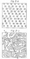
- Figures 3-a, 3-b and 3-c, respectively, are schematic views for illustrating the manner of the aforesaid control in the process of this invention having regard to the state of formation of the molten phases in the molten macroblend versus the size of the small openings of the spinneret.
- a boundary line between molten phases is apparently larger than one-fourth (equal to the length of one side of a small square) of the length of a partitioning member which defines one small opening
- a fine stream extruded through the small opening of the spinneret contains at least two distinct molten phases of at least two dissimilar polymers (when the fine stream is solidified and becomes a fiber, the individual molten phases form blocks in the fiber).
- the theoretical number of blocks in the composite fiber obtained in the case of Figure 3-a is calculated as 3.5, which is nearly equal to the average number (about 3.5) of blocks contained in the four differently-directed small squares.
- the formation of the molten macroblend can be desirably controlled by the size of small opening in the spinneret, namely the length of a partitioning member which defines one small opening, and the state of formation of the molten polymer phases in the molten macroblend, namely the length and number of the boundary lines between the molten polymer phases.
- Figure 3-b is a schematic view showing an embodiment in which a polymer melt consisting of a molten phase (sea) of a polymer matrix and many molten phases (islands) of a different polymer dispersed in the sea is cut by small openings.
- a polymer melt consisting of a molten phase (sea) of a polymer matrix and many molten phases (islands) of a different polymer dispersed in the sea is cut by small openings.
- four squares of a a medium size represent the small openings, and many small squares represent the islands.
- the length of a boundary line between molten phases (the peripheral length of an island) is equal to one-fourth of the length of a small opening.
- the theoretical number of blocks ( N o (B)), according to the above equation, is 4.6.
- the desirable assembly of composite fibers in accordance with this invention which contain at least two blocks coalesced side by side can be produced by the process of the invention by using a molten macroblend and a spinneret in which many effective boundary lines continous boundary lines between different molten polymer phases exist each of which lines has a length larger than one-fourth of the length of a partitioning member which defines one small opening in the spinneret.
- a desirable assembly of composite fibers having side-by-side coalesced blocks in accordance with this invention can also be produced from a polymer melt containing relatively randomly distributed molten polymer phases by controlling the cord length [ L (c)] and the length [ L (w)]of a partitioning member which defines one small opening of the spinneret, if there exist many effective boundary lines between the molten polymer phases each of which lines is larger than one-fourth of the length of a partitioning member which defines one small opening of the spinneret.
- the cord length (E(c)) is the average quotient obtained by dividing the length of a line segment AB (AB) formed by the crossing of a given straight line G drawn through a unit region composed of a square each side of which is of a given length (e.g., 10 mm) with a boundary of the unit region, by the sum [n(p)] of the number of intersecting points formed within the unit region of the straight line G and boundary lines between the polymer phases which are longer than L(w)/4 plus one (many straight lines G are drawn in the unit region, and the average (n(p)) of the quotients for these straight lines is determined).
- the process of this invention can be advantageously practiced by preparing a molten macroblend in which at least one of the length and number of continuous effective boundary lines between different molten polymer phases is controlled and feeding the molten macroblend into the spinneret.
- the process of the invention can be more advantageously practiced by preparing the molten macroblend such that there exist many continuous effective boundary lines between the different molten polymer phases each of which has a length larger than the length of a partitioning member which defines one small opening in the spinneret.
- the molten macroblend is such that in a phantom cross section taken parallel to the spinneret, at least one molten polymer phase forms a continous phase extending long with a small width, particularly a lameller structure.
- the process of the invention can also be advantageously performed by controlling at least one of the average length (L(p)) and number (N(p)) of the effective continuous boundary lines between the dissimilar molten polymer phases and the average length (L(w)) of a partitioning member which defines one small opening in the spinneret in such a manner as to give an assembly of many fibers which have blocks which are about one to about two times as many as the theoretical number of blocks ( N o (B)] defined by the following equation and cutting many boundary lines between the dissimilar molten polymer phases with partitioning members defining the small openings in the spinneret.
- Such a process is applied to a molten macroblend in which the dissimilar molten polymer phases are of a relatively orderly shape, such as a shape extending long with a small width.
- this process can give an assembly of composite fibers containing blocks the number of which approximately equals the theoretical number (N /(B)) of blocks defined by the equation given hereinabove.
- a molten macroblend in which at least one molten polymer phase is of a relatively orderly shape as in the case of a continuous molten polymer phase which extends long with a small width can be fed into the spinneret while controlling the average length and number of the continuous effective boundary lines between the molten polymer phases. Accordingly, the desired blended condition can be created freely by using the laminated plate-type static mixer, and the number of blocks in the resulting assembly of composite fibers can be controlled easily to the desired value.
- the process of this invention can be advantageously practiced by controlling the cord length (L(c)) represented by the following equation defined by the average length [L(p)] and number [ N (p)] of the continuous effective boundary lines between the different molten polymer phases, and the average length [L (w)] of a partitioning member which defines one small opening in the spinneret in such a manner as to give an assembly of many fibers containing blocks the number of which is about one to about 2 times the theoretical number of blocks [ N o (B)] defined by the following equation and cutting the many boundary lines between the dissimilar molten polymer phases with the partitioning members defining the small openings in the spinneret.
- the cord length (L(c)) represented by the following equation defined by the average length [L(p)] and number [ N (p)] of the continuous effective boundary lines between the different molten polymer phases
- the average length [L (w)] of a partitioning member which defines one small opening in the spinneret in such a manner as to
- Such a process is applied to a molten macroblend in which the dissimilar molten polymer phases are relatively randomly distributed.
- a spinneret capable of forming one fiber from one small opening as in the case of a plain weave wire mesh and a spinneret capable of forming one fiber from two small openings as in the case of a twill weave wire mesh are used, there can be produced an assembly of composite fibers having blocks the number of which is nearly equal to N o (B) and an assembly of composite fibers containing about twice as many blocks as No(B)_
- a molten macroblend having ralatively randomly distributed molten phases needs to have many continuous effective boundary lines between the dissimilar molten polymer phases each of which has a length larger than one-fourth of the length of a partitioning member which defines one small opening in the spinneret.
- Such a molten macroblend can be advantageously prepared by using a Kenics-type static mixer to be described.
- the molten macroblends to be fed into the spin- nert in the process of this invention may permissibly contain continuous boundary lines between the dissimilar molten polymer phases which are shorter than one-fourth of the length of a partitioning member which defines one small opening in the spinneret used if only they have many continous effective lines which are longer than one-fourth of the length of a partitioning member which defines one small opening in the spinneret.
- microblend phase The molten phase having such a shorter boundary line is termed a microblend phase in this specification, and such a blended condition is expressed as a microblend.
- Microblend phases may be positively included in the polymer melt used in the process of this invention.
- a microblend phase may frequently occur when the dissimilar polymers used have poor compatibility with each other.
- the term "effective boundary line” is intended to exclude a boundary line of a microblend phase.
- the term “continous” boundary as used herein, means one continuous boundary line contained in a certain area or a part of one continuous boundary line which is cut in a certain area.
- the extrusion of the molten macroblend from the spinneret when expressed very conceptually, can be said to be an operation of cutting the molten macroblend fed into the spinneret into many fine streams with the partitioning members defining the small openings in the spinneret so that the macroblended condition of the molten macroblend is substantially reflected.
- the spinnerets suitable for performing such cutting have an opening area ratio, to be defined hereinbelow, which is the ratio of the total area of many small openings to the area of the entire extruding surface of the spinneret, of about 0.1 to about 0.8, preferably about 0.15 to about 0.7.
- the opening area ratio is defined by the following equation. wherein p and a are as defined hereinabove.
- the assembly of composite fibers of this invention can be produced as such by controlling the total length of the continuous boundary lines between dissimilar molten polymer phases and at least one of the size, shape and number of areas defined by the boundary lines in accordance with the above description and thereby allowing the partitioning members defining at least 50% of the entire small openings in the spinneret to cut the boundary lines between the dissimilar molten polymer phases.
- the fibrous assembly of the invention can equally be produced by only slightly modifying the apparatus shown in Figure 4. This can be fully understood from the aforesaid detailed description of the molten macroblend and the small openings of the spinneret, and will require no detailed explanation.
- the static mixer may be provided within or without the die, or both within and without the die, as stated above.
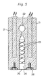
- FIG. 5 is a schematic longitudinal sectional view of such a spinneret.
- the reference numeral 21 represents an electric heater for maintaining the spinneret at the desired temperature
- the reference numeral 22, represents a passage of an I-die through which at least two dissimilar polymer melts pass. In the passage 22, no intensional mixing of the polymer melts is performed.
- the static mixer shown at 23 is provided upstream of a mesh spinneret 25.
- the static mixer is of the Kenics type.
- Shown at 24 is a zone through which the molten macroblend from the static mixer flows to the mesh spinneret 25. The zone 24 serves as a reservoir for the polymer melts.
- the mesh spinneret 25 is firmly fixed by a fastener 26.
- the laminated plate-type static mixer to be described hereinbelow may be equally used instead of the Kenics type static mixer.
- the static mixer outside the die, it may be installed at the mixer section 6 shown in Figure 4. Thus, when it is desired to have the static mixer both in and outside the die, it may be provided at the inside 8 of the die and at the mixer section 6.
- the Kenics static nixer is preferred as the mixer to be provide outside the die.
- the Kenics static mixer as can be seen from Figure 5, can be expressed as having a structure in which one or a plurality (for example up to 10) of dividing plates are provided for dividing the molten polymer phase in two or more sections.
- a mesh spinneret 9 is disposed beneath the extrusion die 7. From the spinneret 9, the polymer melt is extruded and solidified into fibrous fine streams, whereby an assembly of fibers is obtained. It is essential that by supplying a cooling fluid (e.g., air) to the polymer extruding surface of the mesh spinneret or to its neighborhood, the attenuated melt should be solidified while taking-it up.
- a cooling fluid supplying device 11 is provided which has a nozzle or slit so that the cooling fluid can be supplied at a certain speed uniformly to the entire extruding surface of the mesh spinneret.
- the cooling fluid is supplied to the extruding surface of the mesh spinneret or to its neighborhood so that the solidification length (P(S)) becomes not more than 2 cm.
- the solidification length (P(S)) denotes the distance over which a fine polymer stream leaving the surface of an elevation in the spinneret travels until it is solidified.
- the resulting assembly 10 of many composite fibers is taken up by a pair of take-up rollers 12.
- the assembly of composite fibers can be taken up with substantially the same width as the width of the mesh spinneret. It can be fed to a subsequent step, for example a drawing step while its width is being kept the same.
- the drawing apparatus consists of a pair of nip rollers 12 which concurrently serve as take-up rollers and another pair of nip rollers 14 and a hot plate 13 interposed between these pairs of rollers.
- the drawing device and method mentioned above are mere examples, and can be replaced by various other devices and methods to be described hereinabove.
- the drawin fibrous assembly 15 may be directly utilized, or can be sent to other processing steps, such as a splitting step, a crimping step, a cutting step (a step of forming short fibers), a fiber-spreading step, or a web-forming step.
- steps to be performed subsequent to the drawing step are not shown.
- the fine streams from the spinneret can be taken up in accordance with the process of this invention so that the packing fraction (PF) defined by the following equation becomes 10-4 to 10 -1 which is much higher than that (on the order of 10 -5 at most) in a conventional melt-spinning process.
- PF packing fraction
- the packing fraction (PF) represents the sum of the cross-sectional areas of the entire fibers of the fiber assembly formed per unit area of the fiber-forming area of the spinneret, and constitutes a measure of the density of fibers spun from the fiber-forming area, that is, the high-density spinning property.
- the apparent draft ratio (Da) is defined by the following equation.
- a mixer to be built in the extrusion die 8 (or the mixer section 6) for forming a molten macroblend suitable for the practice of the process of the invention by mixing at least two dissimilar molten polymer phases For example, various static mixing units used normally in the mixing of molten polymers can be used either singly or in suitable combinations as the mixer for use in the present invention.
- mixers that can be used in this invention include a porous mixer obtained by closely aligning and laminating many porous corrugated plates in the longitudinal direction at certain intervals, a porous mixer made by closely aligning and laminating many wire meshes of a plain weave and/or twill weave in the longitudinal direction, and a thin porous mixer made by closely filling and aligning many minute metallic balls and sintering them and thus bonding them to each other.
- static mixers include, for example, a static mixer of Kenics Corp., a Sulzer static mixing unit of Gebruder Sulzer AG, Ross ISG mixer of Charles Ross Co., a square mixer of Sakura Seisakusho, a Komax mixer of Komax System, Co., and a Bayer continuous mixer of Bayer AG.
- the fibrous assembly of the invention can be advantageously produced by mixing at least two dissimilar molten polymer phases by the static mixer and substantially maintaining the mixed state of the molten polymer phases which have left the static mixer until the mixture reaches the spinneret.
- the process of the invention is advantageously carried out by forming a mixed molten polymer phase of a relatively orderly shape in which at least one molten polymer phase extends long with a small width, partially that having a lamellar structure.
- a laminated plate-type static mixer to be described in detail is recommended.
- a molten macroblend in which at least one molten polymer phase in a cross section taken parallel to the spinneret extends long with a small width, in particular at least one said molten polymer phase is of a lamellar structure, permits easy control of the shape and size of the polymer phase in the fiber or the number of blocks therein, and can give the desired fibers advantageously.
- the molten macroblend in which at least one molten polymer phase extends long with a small width, particularly has a lamellar structure can be formed by using a static mixer having the following constituent elements (a) to (e).
- the mixer having the above constituent elements (a) to (e) is referred to as a "laminated plate-type static mixer".
- a laminate plate-type static mixer is a new type of mixer not known heretofore.
- this type of mixer there can be easily obtained a molten macroblend in which a number of molten phases of at least two dissimilar polymers are coalesced in a lamellar structure, i.e. in a thin laminar flow.
- a very thin layer-like melt can be obtained.
- the combination of polymer phases can be changed optionally, the thickness of each polymer phase can be controlled easily, a uniform and specified layer-like polymer melt can be easily obtained, and the mixer is simple in structure and can be easily built.
- the mixer in combination with the spinneret for the production of the fibrous assembly of the invention, it can also be used in other applications.
- the static mixer of the invention can be advantageously applied to the mixing of at least two fluids to give a molten macroblend the formation of which is difficult with conventioal mixers because of the differences in physical properties such as the surface tension, interfacial tension, viscosity and solubility parameter of the fluids or the influences of chemical properties such as reactivity.
- FIGS. 6-a and 6-b are enlarged schematic views of embodiments of the laminated-plate type static mixer in accordance with this invention.
- the plates having a depressed portion which constitute the static mixer of the invention are preferably flat plates. They may, however, be of other shapes, such as wavy shape as shown in Figure 6-a.
- the plates should at least be such that when they are used as a laminated assembly, fluids do not overflow or leak into areas other than the depressed portions, and the fluid flows which have left the depressed portions are laminated in a multiplicity of layers.
- Figure 6-a specifically shows a mixer consisting of two different types of plates P-a and P-b having depressed portions of different shapes which are alternately laminated. For easy explanation, one plate P-a is shown away from the assembly on the left side of the drawing.
- the depressed portions provided in the plates act as a passage or channel for passage of fluids, and shown hatched in the drawing in plates P-a and P-b.
- the depressed portions in a laminated assembly of the plates, form inlets for introduction of fluids (a l , a 2 and a3 in P- a and b l , b 2 , b 3 and b 4 in P-b) and outlets for discharging the fluids (shown at X a in P-a and X b in P-b), and in one plate the fluid inlets and outlets communicate with each other.
- the depth (t 2 ) of the depressed portion is smaller than the thickness (t 1 ) of the plate, and is preferably satisfies the following expression. wherein t l is the thickness (mm) of the plate, and t 2 is the depth (mm) of the depressed portion.
- t 1 and t 2 are as defined hereinabove.
- the thickness (tl) of the plate is generally in the range of 0.05 to 2 mm, preferably 0.1 to 1 mm, especially preferably 0.2 to 0.7 mm.
- a set of plates P-a are laminated alternately with a set of plates P-b so that excepting the plates at the ends any one plate P-a or P-b is interposed between two plates P-b or P-a respectively.
- the depressed portion of the plate P-a is shown by righthandedly upwardly extending hatches, and the depressed portion of the plate P-b, by righthandedly downwardly extending hatches, and these depressions differ from each other in shape.
- the shapes of these depressed portions can be freely designed so long as they meet the requirements described hereinabove.
- the shape of the depressed portion can be optionally determined by considering the size, shape, number of position of fluid inlets and the size, shape and position of fluid outlet.
- An island-like elevation such as shown at Ia in plate P-a and Ib in plate P-b may be provided in the depressed portion. At least one such island-like elevations may exist in the depressed portion. The provision of such island-like elevations improves the shape retention of a mixer constructed by laminating the plates, and also makes it easy to control the pressure and flow rate of a fluid flowing through the depressed portion.
- the island-like elevation mah be located on the fluid outlet X a as is the case with Ia in Figure 6-a, or may be located in an inward portion of the derpessed portion as is the case with Ib in the plate P-b.
- the laminated plate-type static mixer is characterized in that the fluid inlets of plates having depressed portions of the same shape form a common inlet for the same fluid and thus the laminated structure has at least two common inlets for at least two different fluids, and that the fluid outlet is formed so as to give at least two fluid flows adjoining each other.
- two different types of plates P-a and P-b in large number are laminated alternately so that two fluid outlets X a and X b are formed on the same plane so as to give two different fluid flows aligned side by side.
- the plates P-a and the plates P-b face in the same direction along the laminating direction, and the fluid inlets a 1 , a 2 and a3 of the plates P-a each occupy the same position in a band form, and likewise, the fluid inlets b l , b 2 , b 3 and b 4 of the plates P-b each occupy the same position in a band form.
- the fluid inlets a 2 of the plates P-a form a common band-like fluid inlet A 2
- the fluid inlets a 3 of the plates P-a form a common band-like fluid inlet A3.
- the fluid inlets a 1 of the plates P-a also form a common band-like fluid inlet.
- the fluid inlets b l , b 2 , b 3 and b 4 respectively form common band-like fluid inlets (for example, B 2 , B 3 and B, corresponding to b 21 b 3 and b 4 in Figure 6-a).
- the plates P-a and P-b respectively have three and four fluid inlets.
- the number of fluid inlets in each plate may be from 1 to 4.
- the same polymer melt should desirably be introduced from a plurality of fluid inlets provided in the same type of plates. For other purposes, this is always necessary, and different fluids may be introduced from such inlets.
- the number and positions of fluid inlets in each plate are determined in consideration of the type, amount, etc. of fluids to be introduced into the individual plates in order that a fluid flowing from the fluid outlet X a of the plate P-a and a fluid flowing from the fluid outlet Xb of the plates P-b may contact each other on the same plane as layers and form a molten macroblend having a uniform lamellar structure.
- the individual common fluid inlets may be located on the same or different planes of the laminated assembly.
- the common fluid inlets B 2 , A 2 and B 3 are on the same plane, and the commone fluid inlets A3 and B4, on a different plane.
- a common fluid inlet based on the inlets a l and a common inlet based on the fluid inlets b 1 are located on still another plane of the laminated assembly.
- the plate P-a has a fluid outlet X a
- the plate P-b a fluid inlet outlet X b
- the two types of fluid outlets X a and X b are located on the same plane of the laminated assembly and form one fluid discharge zone. At least two fluids make substantial contact with each other for the first time in this fluid dischatge zone after they have passed through the depressed portions of the individual plates, whereby they form one fluid having a lamellar structure.
- the fluid outlets of plates having depressed portions of the same shape may be located substantially on the same plane.
- all of the fluid outlets of the different plates having differently-shaped depressed portions are located on the same plane.
- the plate having a depressed portion has a width (W) of generally 5 mm to 10 cm, preferably 1 cm to 50 cm, and a height (H) of 5 mm to 50 cm, preferably 1 cm to 30 cm.
- One or a plurality of small holes extending through the plate may be formed in the depressed or other portions of the plate.
- a small hole H is formed in the non-depressed portion of the plate P-a
- a small hole H b is formed in the depressed portion of the plate P-b.
- These small holes H and H b are formed for pressure adjustment or movement of a small proportion of fluid between two plates having the same depressed shape (for example, between two plates P-a or between two plates P-b) or between two plates having different depressed shapes (for example, between the plate P-a and the plate P-b), and the diameter, number and positions of the small holes are determined as required according to the purpose of providing such small holes.
- Figure 6-b shows a laminated plate type static mixer consisting of at least two types of plates having different raised and depressed shapes which are laminated alternately.
- This static mixer is suitable for obtaining a mixed fluid having a lamellar structure in which two types of fluids are associated in layers uniformly and regularly.
- the two types of plates may be laminated in suitable combinations, for example as in (P-a + P-a + P-a + P-b), (P-a + P-a + P-b), or (P-a + P-b + P-b). Or at least three types of plates having different depressed portions may be laminated alternately or in suitable combinations.
- the static mixer of the invention consist only of many plates having at least two different depressed shapes. If desired, smooth plates or porous plates having no depressed portion (e.g., plates of sintered metal, fibrous webs, woven fabrics, .wire meshes, etc.) may partly be incorporated in the laminated assembly.
- Figure 6-b shows is an enlarged schematic perspective view of another typical embodiment of the laminated plate-type static mixer which is viewed from the fluid discharge side.
- the mixer shown in Figure 6-b consists of different types of plates P-c and P-d having depressed portions of different shapes which are laminated alternately in a regular fashion.
- Each of the plates P-c and P-d has one fluid inlet.
- the fluid inlets of the plates P-c form a common band-like fluid inlet A 1
- the fluid inlets of the plates P-d form one common band-like fluid inlet B 1 .
- Fluids introduced from the common fluid inlets A l and B l respectively pass through the depressed portions of the plates P-c and P-d and are discharged from fluid outlets X c and X d , respectively.
- the distance between the fluid flow inlet of the static mixer and the mesh spinneret should not be too long, and an obstacle to the flow of the molten phases should not be present between them to the greatest possible extent. It is more preferred that the area of the molten polymer flowing from the static mixer should be substantially be greatly different from that of the mesh spinneret, and that there should not be a great difference between the shapes of the two.
- an additional static mixer may be provided between the aforesaid laminated plate type static mixer and the mesh spinneret if it does not greatly disturb a boundary line between at least two dissimilar molten polymer phases.
- the assembly of many fibers prepared by the process of this invention described hereinabove may be used in the as-spun state or may be drawn before use.
- the drawing operation decreases the average denier size of the fibers and improves the physical properties of the fibers, particularly their strength and degree of orientation, over the as-spun fibrous assembly, but in many cases does not substantially change the state of blocks in at least two different polymer phases in a cross section of the fibers.
- the drawn fiber assembly thus retains the characteristics of the fiber assembly described hereinabove.
- the method for drawing the fiber assembly will be described in detail below.
- the fibrous assembly is obtained in the form of a thin sheet in a direction at right angles to the fiber axis.
- the sheet-like assembly consisting of substantially parallel-laid fibers
- this is advantageous.
- the undrawn fibrous assembly produced by the spinning process of this invention is conducted to a frictional guide, such as at least one tubular friction body (e.g., the member 12 shown in figure 4), and is drawn by maintaining the feeding speed (U 1 ) of the undrawn fibrous assembly at the tubular friction body lower than the takeup speed (V 2 ) of the fibrous assembly after drawing (U 1 ⁇ U 2 ) in such a manner that no tension extends to the spinneret.
- a frictional guide such as at least one tubular friction body (e.g., the member 12 shown in figure 4)
- the fibrous assembly By providing a heating zone (for example, the hot plate 13 shown in Figure 4) between the friction body and means for taking up the drawn fibrous assembly, the fibrous assembly can be hot-drawn immediately after the spinning. As a result, the drawn fibrous assembly can be easily produced.
- a heating zone for example, the hot plate 13 shown in Figure 4
- the mounting position or angle of the frictional guide may be optional if it can restrict the speed (V 1 ) of the undrawn fibrous assembly.
- the frictional guide may be at least one of plates, tubes, square objects, tooth-like structures, or rollers, or a combination of two or more of these different types of frictional guides may be used. At least one pair of rollers of the substantially nipping type may also be used.
- the surface of the frictrional guide may be finished, for example, by mirror-finishing plating, or in a crepe weave or a special raised and depressed pattern, or by resin coating. But any frictional guide which can restrict the speed (V 1 ) of the undrawn fibrous assembly can be used in this invention irrespective of its material and shape.
- the degree (V 2 /V I ) of drawing the fibrous assembly can be varied by suitably changing the types of the fiber-forming polymers which constitute the fibrous assembly, the shape of the guide frictional guide, the form and material of its surface, and the combination and temperature of heaters in the heating zone.
- the drawing is desirably carried out at a draw ratio of 1.1 to 10, preferably 1.5 to 5.
- the fibers constituting the fibrous assembly of the invention have an irregular periodic variation in cross-sectional area along its longitudinal length in their cross section, at least two dissimilar polymer phases are coalesced side by side.
- the fibrous assembly is drawn while the draw ratio is increased, it never happens that the assembly as a whole is broken at a time at a certain fixed position. But as the draw ratio increases, the fibers may partly be broken gradually or partly split. This is also within the scope of the invention so long as the assembly to be drawn is not wholly broken.
- the drawing of the fibrous assembly of the invention is advantageous and characteristic in that even such partial breaking or partial splitting occurs, the entire fibrous assembly can be drawn without any trouble.
- the temperature of the fibrous assembly of the invention may be from room temperature to a temperature below the point at which the polymers constituting the fibers melt.
- the preferred drawing temperature depends upon the types, combination and proportions of at least two dissimilar polymer phases which constitute the fibers, and the shape and number of blocks in the polymer phases.
- the preferred drawing temperature is from room temperature to a point lower than 0.9 times the apparent melting point in absolute temperature ( o K) of a polymer phase having the lowest apparent melting point among the dissimilar polymer phases. Since the drawing temperature is also greatly affected by the means, speed and ratio of drawing, it can be optimized by repeating simple experiments.
- the undrawn fibrous assembly of the invention is characterized by the fact that the cross-sectional area of each fiber varies irregularly along its longitudinal direction, the cross-sections of the constitutent fibers differ from each other in at least one of shape and size, and the size of the blocks in a fiber cross section varies along its longitudinal direction. Accordingly, the fibrous assembly of the invention is free from a variation in the stability of the drawn condition due to slight differences in temperature, which variation is seen in the drawing of a conventional assembly of uniform fibers.
- the drawing can be easily effected within a broader temperature range than those conventionally employed, and an assembly having partly broken fibers or an assembly having partly split fibers can be obtained.
- a fibrous assembly similar to a sliver in frame spinning, and a bulky yarn-like assembly having similar properties to spun yarns can be produced directly with ease.
- At least one heater is provided preferably in a path of the fibrous assembly.
- the gradient of the heating temperature in a single heater can be controlled suitably.
- one-stage drawing but also multi-stage drawing can be easily effected by dividing the heating zone into a plurality of sections, providing a plurality of heaters in the thus divided heating zone, and prescribing a suitable temperature in every one of the heaters.
- the heater to be used in the heating zone may be a contact-type heater having a heating function, such as a flat plate, a curved plate, a plate processed in a raised and depressed pattern, or a pin, or a noncontact- type heater such as radiation heat, an electric heater, hot steam, or hot air.
- a contact-type heater having a heating function, such as a flat plate, a curved plate, a plate processed in a raised and depressed pattern, or a pin
- a noncontact- type heater such as radiation heat, an electric heater, hot steam, or hot air.
- the drawing operation tends to be affected by the surface roughness of the heater.
- the length of the heater on the path of the fibrous assembly may be opltional.
- the heater has such a structure as can supply heat uniformly to the fibrous assembly in its widthwise direction.
- the drawing of the fibrous assembly may be facilitated by applying a surface-treating agent such as an oiling agent to the fibrous assembly by coating or impregnation.
- a surface-treating agent such as an oiling agent
- the fibrous assembly of the invention can be converted to crimped yarns by a simple method which does not require a complex operation such as mechanical crimping frequently practiced in the crimping of fibers.
- crimping can be easily imparted to the fibrous assembly of the invention by heat-treating it under tension or under no tension in dry heat, boiling water, etc., or in some case, by simply drawing it.
- the crimped yarns so obtained are characteristic in the shape and structure of the crimps because in the fibrous assembly of the invention, at least 90 % of the constituent fibers have a non-circular cross section, the cross sections of many of the fibers differ from each other in at least one of shape and size, and at least 50 % of the fibers of the assembly have at least two side-by-side coalesced blocks of at least two dissimilar polymer phases, at least one of the number, shape and size of the blocks varying from fiber to fiber.
- the crimping treatment gives more complex crimps than in the case of crimped yarns from composite fibers having uniform block shapes obtained by conventional melting methods.
- the resulting crimps are fine and occur irregularly and three-dimensionally.
- each of the fibers constituting the fibrous assembly of the invention has a cross section varying in size irregularly and periodically along its longitudinal length, the combination of this feature with the aforesaid characteristics of the shape of the blocks makes it possible to give crimped yarns having very fine irregular and three-dimensional crimps. Accordingly, there can be obtained a fibrous assembly which have crimps, is bulky and has excellent elastic recovery.
- the average number of crimps is preferably 3 to 20 per inch, especially preferably 5 to 15 per inch.
- the crimp ratio is preferably 10 to 50 %, more preferably 15 to 45%. A highly crimped fibrous assembly having these properties can be obtained according to the invention.
- the crimped fibrous assembly can be directly used as a cushioning material and a heat insulating material. It may also be converted to a web and used as a material for nonwoven fabrics.
- the fibrous assembly of the invention can be changed to an assembly consisting of partly split fibers by drawing.
- the assembly of partly split fibers provided by this invention can also be produced by appying a physical external force such as crumpling or napping, or such a means as heat-tretment or swelling treatment, or a combination of these.
- the assembly of composite fibers in accordance with this invention which can be split depends basically upon the types of the dissimilar polymers to be coalesced and the shape of the blocks. Partial splitting occurs relatively easily with a combination of polymers having poor adhesiveness, for example a combination of polyethylene terephthalate and polypropylene, or with an assembly in which the boundary lines between blocks extend relatively long.
- the assembly of composite fibers composed of at least two different fiber-forming polymers can be produced.
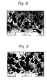
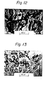
- At least 90 %, preferably at least 80 %, especially preferably at least 70%, of the constituent fibers in this cross section have a non-circular cross-sectional shape. From Figures 7 to 16, most of the fibers constituting the assembly of the invention have a non-circular cross sectional shape.
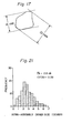
- the degree of cross-sectional non-circularity can be quantitatively expressed by the irregular shape factor (D/d) which is the ratio of the maximum distance (D) between two parallel lines circumscribing a fiber cross section to the minimum distance (d) between the two circumscribed parallel lines.
- D/d irregular shape factor
- Each of the fibers having a non-circular cross section constituting the assembly of the invention preferably have an irregular shape factor of at least 1.1.
- the cross sections of at least 50 %, preferably at least 45%, especially preferably at least 40%, of the fibers differ from each other in at least one of shape and size.
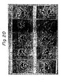
- the cross sections having a nonuniform shape and/or size can be distinguished by microscopic observations as can be seen from Figures 7 to 16.
- the cross sections having different sizes can be determined quantitatively by the intra-assembly fiber cross-sectional area variation coefficient [CV(A)] given by the following equation wherein S(A) is the average of the cross-sectional sizes of 100 fibers which are obtained by sampling at random a partial assembly of 100 fibers from the fibrous assembly of the invention, and microscopically meassuring the cross-sectional sizes of the individual fibers in a cross section taken at an arbitrary position of the partial assembly, and ⁇ (A) is the standard deviation of the cross-sectional areas of the 100 fibers.
- CV(A) intra-assembly fiber cross-sectional area variation coefficient
- Fibers having different cross-sectional sizes which constitute the fibrous assembly of the invention have a CV(A) of preferably 0.05 to 1.5, more preferably 0.1 to 1.5, especially preferably 0.2 to 1.
- the assembly of composite fibers in accordance with this invention is such that at least 50% of two cross sections sampled at random from the cross sections of the aforesaid fibers viewed by a microscope have
- the fibrous assembly of the invention When the fibrous assembly of the invention is cut at an arbitrary position at right angles to the fiber axis, at least 50 %, preferably at least 45%, more preferably at least 40%, of the fibers each have in their cross section at least two side-by-side coalesced blocks of at least two dissimilar fiber-forming polymer phases with at least a part thereof being exposed to the peripheral surface of the fiber, and at least one of the number, shape and size of the blocks vary from fiber to fiber. It should be understood that the side-by-side coalesced blocks exclude those blocks which are completely embraced within the fiber cross sections and are not exposed to the peripheral surfaces of the fibers.
- Figures 7 to 16 show at least two side-by-side coalesced blocks in a cross section of a fiber in the fibrous assembly of the invention.
- At least 50 % of the fibers which constitute the fibrous assembly of the invention have a cross section having at least two side-by-side coalesced blocks in.accordance with the above definition. It will be readily appreciated from the description of the process of this invention that the ratio of cross sections having at least two side-by-side coalesced blocks can be varied depending upon the state of formation of a molten macroblend phase and the size of the small openings in the spinneret.
- the number of side-by-side coalesced blocks should be construed to be the number of independent blocks at least a part of which is exposed to the peripheral surface of the fiber.
- the number of blocks contained in a small square area on the right top is four, and the number of blocks contained in a small square on the right bottom is three.
- one cross section of each of the fibers contain preferably 1.5 to 30, more preferably 2 to 5, on an average of side-by-side coalesced blocks of at least two dissimilar fiber-forming polymer phases with at least a part thereof being exposed to the peripheral surface of the fiber.
- the average number of blocks of polymer phases in a fiber is referred to as N( B ).
- the fibrous assembly of the invention has such a distribution of the number of blocks that the intra-assembly fiber block number variation coefficient [CV(AB)] expressed by the following formula is in the range of 0.05 to 1.0, preferably 0.1 to 0.8, especially preferably 0.15 to 0.7.
- N(B) is the average number of blocks in the cross sections of 100 fibers which is obtained by sampling a partial assembly of 100 fibers at random from the fibrous assembly of the invention, and microscopically measuring the number of blocks in each of the fibers in a cross section taken at an arbitrary position
- o(AB) is the standard deviation of the number of blocks in the 100 fibers.
- the fibrous assembly of composite fibers provided by this invention have an average fiber denier (Te), as defined below, of 0.01 to 1,000 denier, preferably 0.05 to 800 denier, more preferably 0.1 to 500 denier.
- Te average fiber denier
- the average denier size (De) in the assembly can be determined as follows:
- the average denier size ( D e) in the assembly is calculated in accordance with the following equation.
- m(A) is the weight average value of the photographic fiber cross sections cut off; and K is a denier calculating factor defined by the equation in which y is the weight (g) of the unit area of the photograph, 6 is the ratio of area enlargement of the photograph, and p is the specific gravity of the fiber-forming polymers, all of these values being expressed in c.g.s. unit.
- the fibrous assembly of this invention may contain 2 to 5, preferably 2 to 3, dissimilar fiber-forming polymer phases.
- At least two blocks in each fiber may respectively be composed of a single polymer phase, or of a microblend phase in which in a matrix of one polymer at least one other polymer is dispersed.
- each block consists of a single polymer phase.
- an assembly of fibers in which at least one block appearing in a fiber cross section by microscopic observation is coalesced with another block with a clear boundary line therebetween, said at least one block being composed of a matrix of at least one single polymer in which at least one other polymer is dispersed.
- Figure 16 shows this embodiment.
- each of the fibers which constitute the fibrous assembly of the invention preferably has an irregular periodic variation in the size of cross sectional area along its longitudinal length.
- the variation in the size of cross sectional area can be expressed by the intrafiber cross-sectional area variation coefficient [CV(F)] given by the following formula.
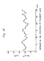
- Any 3 cm-length is selected in a given fiber of the fiber assembly, and the sizes of its cross-sectional areas taken at 1 mm intervals are measured by using a microscope. Then, the average (S(F)) of the sizes of the thirty cross-sectional areas, and the standard deviation (aF) of the thirty cross-sectional areas are calculated. Based on these values, CV(F) can be computed in accordance with the above equation.
- Each of the composite fibers which constitute the fibrous assembly of this invention preferably has an intrafiber cross-sectional area variation coefficient [CV(F)] in the ragne of 0.05 to 1.0.
- Figure 18 shows the intrafiber cross-sectional area variation of fibers obtained in Example 16 given hereinbelow.
- constituent fibers in the fibrous assembly of the invention are such that when a 5-cm length of one fiber is selected and cut at 5 mm intervals at right angles to the longitudinal direction of the fiber and the resulting ten cross sections are observed by a microscope, the cross sections have at least two side-by-side coalesced blocks of at least two dissimilar fiber-forming polymer phases with at least a part thereof being exposed to the peripheral surface of the fiber, and in each of these cross sections, at least two of said blocks differing in size (area) exist.
- Polycarbonates derived from various bisphenols, polyacetal, various polyurethanes, polyfluoroethylene, and copolyfluoroethylene derived from various bisphenols, polyacetal, various polyurethanes, polyfluoroethylene, and copolyfluoroethylene.
- plasticizers In order to increase the plasticity or melt viscosity of the polymers, plasticizers, viscosity increasing agents, etc. may be added. Furthermore, the polymers may include usual additives for fibers, such as light stabilizers, pigments, heat stabilizers, fire retardants, lubricants, and delusterants.
- the polymers are not necessarily linear polymers, and may be of a partially crosslinked three-dimensional structure so long as their thermoplastic properties are not impaired.
- the assembly of composite fibers and the filaments in accordance with this invention are produced by using at least two kinds of the above polymers.
- the fibrous assembly of the invention consists of at least two dissimilar fiber-forming polymer phases having a difference in apparent melting point of at least 3 0 C, melting point of the polymer phase means [when the dissimilar polymer phases each consist of a single polymer, the apparent melting point of the polymer phase means that of the single polymer; and when at least one of the polymer phases consists of at least two dissimilar polymers, the apparent melting point is the sum of the products obtained by multiplying the mixing weight ratio of the dissimilar polymers (the total ratio being taken as 1) by the melting points (°C) of the respective polymers).
- Two dissimilar polymers mean not only two quite different kinds of polymers such as a combination of polyethylene terephthalate and polypropylene, but also a combination of polymers of the same kind but having different degrees of polymerization (for example, a combination of polyethylene trephthalate having an intrinsic viscosity of 0.96 and polyethylene terephthalate having an intrinsic viscosity of 0.49) or polymers of the same kind having different terminal groups (for example, a combination of polyamides having different kinds of terminal amino groups), or a combination of a linear polymer and a partially branched polymer of the same kind (for example, a combination of polyethylene terephthalate and polyethylene terephthlate having pentaerythritol as a branching agent copolymerized therewith).
- the two dissimilar polymers may also include a combination of two polymers having different melting points, specific gravities, hardnesses, degrees of crystalilzation, solvent resistances or dyeabilities, or a combination of two polymers having in the form of a fiber different heat shrinkages, orientation degrees, tenacities, elongations and polarizing properties.
- At least two dissimilar polymers are polyesters
- these polyesters differ from each other in at least one of the following phsical properties and chemical properties.
- the dissimilar polymer phases in a filament can be easily distinguished by cutting the filament at right angles to its axis, and observing the cross section with a polarized microscope, or by placing it on a hot plate and observing its molten state by a microscope; or by dyeing the cross section and observing it with a microscope; or by scratching the cross-sectional surface by electron ion etching and observing the roughness of the surface with an electron scanning microscope (for example, at a magnification ratio of about 1000).
- polymers heretofore used in melt-spinning processes such as polyethylene terephthalate, poly(e-caprolactam), polyhexamethylene adipamide, polyethylene, polypropylene, polystyrene, and polytetramethylene terephthalate can be advantageously utilized.
- the process of this invention makes it possible to easily fiberize polycarbonates and polyester elastomers which have been considered difficult to melt- spin industrially.
- composite fibers can be produced from at least two dissimilar polymers which have heretofore been difficult to form into composite fibers because of the large differences in the degree of polymerization, and therefore in melt viscosity.
- At least two dissimilar polymer phases each have at least two side-by-side coalesced blocks, and therefore, as already stated with regard to the manufacturing process, when the two blocks are composed of two dissimilar polymer phases having no adhesiveness to each other, partial splitting treatment can give a fibrous assembly in which the polymer phases are separated from each other along the fiber axis to form finer fibers.
- the assembly of composite fibers of the invention which is partially split is such that when 100 fibers are sampled at random from the assembly, at least 20% of these sampled fibers irregularly have in their longitudinal direction
- the assembly of composite fibers is provided in the form of short fibers.
- Such short fibers have an average fiber length of not more than 200 mm, preferably not more than 150 mm.
- the fiber assembly of this invention cut to short fibers may be used as such or as a mixture with other fibers. If the fiber assembly of this invention is contained in the mixture in an amount of at least 50% by weight, preferably at least 60% by weight, the characteristic features of the fiber assembly of this invention can be exhibited.
- the short fibers either alone or in combination with other short fibers, may be used to produce spun yarns.
- the cross-sectional size and shape of the fiber assembly of this invention, the distribution thereof, and the variations in the number, shape and size of blocks in a fiber cross section taken at right angles to the fiber axis are within certain fixed ranges, and such an assembly of composite fibers cannot be obtained by known fiber manufacturing methods.
- the structural properties of the assembly are interesting and have not been obtained heretofore.
- the distribution of the cross sectional areas of the fibers in the fiber assembly and the distribution of the number of blocks in the assembly are measured with regard to the fibers obtained in Example 16, and Examples 6 and 19, and are shown in Figures 21 and 22.
- the ranges of such cross-sectional size and shape, the distribution thereof, and the variations of blocks along the fiber axis are partly similar to those of natural fibers such as silk and wool, and therefore, the present invention can provide synthetic composite fibers which have similar tactile hand and properties to natural fibers.
- the fiber assembly of this invention can be used as a material for woven or knitted fabrics, non-woven fabrics and other fibrous products.
- the fiber assembly of this invention develops crimps to a greater degree by heat-treatment because of the proper irregularity in the fiber cross section along the longitudinal direction and of the anisotropic cooling effect imparted at the time of forming the fibers. This property can be utilized in increasing fiber entanglement.
- the fiber assembly of this invention is also useful in producing crosslaid nonwoven fabrics, random- laid nonwoven fabrics obtained by application of electrostatic charge or air, artifical leathers, etc.
- a fiber assembly was produced from chips of 6- nylon (melting point 488°K; intrinsic viscosity 1.3) and chips of polypropylene (melting point 438°K; melt index 15) by using an apparatus of the type shown in Figure 4.
- Chips of 6-nylon were continuously metered and fed into an extruder A having an inside diameter of 30 mm and melted and kneaded at 200 to 300°C.
- the molten polymer was sent to a mixer section 6 at a rate of 17 g/min. by means of a gear pump 4a.
- chips of polypropylene were continuously metered and fed into an extruder B having an inside diameter of 30 mm and melted and kneaded at 240 to 310°C.
- the molten polymer was sent to the mixer section 6 at a rate of 14 g/min. by means of a gear pump 4b.
- the molten nylon and polypropylene were mixed at the mixing section 6 by means of a Kenics-type mixer consisting of 10 elements.
- the mixture was extruded by means of an I-die through a mesh spinneret 9 having a band-like fiber-forming area with a size of 160 mmx 5 mm and composed of one 32-mesh plain weave wire mesh.
- air was jetted toward the fiber-forming area of the spinneret at a rate of 9 m/sec. by means of a cooling device 11 having an air jet nozzle and located immediately below the spinneret.
- the polymer melts were spun to give an assembly of composite fibers having 37,000 denier.
- FIG. 7-a A microphotograph of the resulting assembly taken along its cross section is shown in Figure 7-a.
- Figures 7-b and 7-c show similar microphotographs taken after the fiber assembly was cold drawn to about 3 times and then heat-treated for 10 minutes in boiling water.
- the fiber assembly could be drawn under the conditions shown in Table 1.
- the average denier size of the resulting composite fibers determined statistically from a microphotograph of the resulting fiber assembly taken along its cross section, was 0.9 denier.
- the average number of blocks (N(B)) in the resulting assembly determined from the aforesaid microphotograph was 4.0.
- microphotograph showed no fiber having a quadrangular outer configuration which consisted of a single polymer phase in cross section instead of side-by side coalesced polymer phases.
- Example 3 one 30-mesh plain weave wire mesh was used at the spinneret, and the same polyethylene terephthalate and polypropylene as used in Example 3 were used.
- the wire mesh was not attached to the fiber-forming area of the spinneret, but a rectangular stainless steel polymer receiving box was provided.
- the mixed molten polymer was sampled into the receiving box, and cooled in water as such. It was thus quickly solidified while keeping the mixed state of the polymers unchanged.
- the resulting polymer mixture sample was cut in a plane parallel to the spinneret face, and photographed through a microscope. The microphotograph is shown in Figure 24.
- the effective average cord length [L (c)] and the length of a boundary line [N(p) ⁇ L(p)] between dissimilar polymer phases, as defined in the specification, were measured, and found to be 0.42 mm and 373 mm, respectively. It is seen therefore that the length of the boundary line is sufficiently longer than the average length of the partitioning member.
- the 30-mesh plain weave wire mesh was set at the spinneret as partitioning members, and the polymers were spin under the fiberizing conditions shown in Table 1. There was obtained a fiber assembly having a total denier size of 225,000 denier and an average monofilament denier size of 10 denier.
- the average number of blocks [ N (B)] of the assembly in a fiber cross section was 5.5, and from the effective average cord length [ L (c)]showing the mixed state of the polymers, the average theoretical number of blocks (No(B)) calculated in accordance with the equation given in the specification was 5.0, thus showing a good correspondence between [ N (B)]and (No(B)).
- the microphotograph in Figure 10 shows that more than 95% of the constituent fibers of the resulting assembly had a non-circular cross-sectional shape, and the two polymer phases are aligned side by side in a lamellar structure.
- the block portion of the fiber cross-section represents a dyed polyethylene terephthalate portion.
- the resulting fiber assembly was drawn to about 3.5 times at a rod surface temperature of 80 to 120°C in a drawing zone in which three heated rod having an outside diameter of about 5 cm containing a cartridge heater built therein and two rods which were not positively heated were arranged alternately.
- the drawn fiber assembly had the properties shown in Table 2 which indicate good usability of the assembly as a material for general fibrous products.
- the drawn fiber assembly could be easily split by mechanical crumpling.
- Example 5 was repeated except that one 45-mesh plain weave wire mesh shown in Figure 1-a was used instead of the 30-mesh plain weave wire mesh as the material for the extrusion surface of the spinneret.
- the resulting assembly of composite fibers was examined for variations in shape and variations in the number of blocks in a fiber cross section.
- One fiber was selected from the undrawn fiber assembly, and cut at 5 mm intervals along a 5-cm length in the axial direction.
- the variations in the fiber cross sections were traced, and are shown in Figure 19. From the microphotograph of the 10 fiber cross sections, only the fiber cross sections were cut off and rearranged and adhered to make Figure 19. It is easily understood from this Figure that in the cross sections of one fiber, the size of the blocks varies slightly over its 5 cm length, but the number of blocks remains unchanged. The shapes of the blocks change partly symmetrically and partly non-symmetrically.
- the fiber assembly could be drawn in the same way as in EXample 5.
- Example 5 was repeated except that a 12-mesh plain weave wire mesh was used instead of the 30-mesh plain weave wire mesh.
- Figure 12 shows a photograph of the cross section of the resulting undrawn fiber assembly of composite fibers. It is seen that thick fibers having an average monofilament size of 106 denier experienced fiber-forming attenuation within a very short range represented by a solidification length of less than 1 cm.
- the solidification length (P(s)) was measured as follows:
- Example 5 was repeated except that a 40-nesh twill weave wire mesh as shown in Figure 1-b was used instead of the 30-nesh plain weave wire mesh.
- the mixed state of the polymers before cutting with the partitioning members was the same for Examples 5 to 10, and can be seen from the microphotograph of Figure 24..
- the irregular shape factor (D/d) of the fiber cross section was more than 2, and the intra-aseenbly block number variation co- efficient (CV(AB)) was as large as 0.45.
- Example 5 was repeated except that an etched porous plate shown in Figure 1-d was used instead of the 30-mesh plain weave wire mesh.
- the etched porous plate was made as follows:
- the fiber assembly could be drawn as in Examples 5 to 8.
- Example 5 was repeated except that a sintered wire mesh obtained by laminating in a bias direction a 40-mesh plain weave wire mesh and a 30-mesh plain weave wire mesh specially woven from fine wires usually employed for producing 70-mesh plain weave wire ueshes and specially sintering the laminate was used instead of the 30-mesh plain weave wire mesh.
- the mixed state of the polymer phases from the extruders A and B is shown in a microphotograph of Figure 25 taken through a stereomicroscope. One graduation in the scale at the bottom of the photograph correspond to 1 mm.
- the block portion shows the polymer A phase in which polyethylene terephthalate and polypropylene from a microblend, and the white portion shows the polymer B phase composed only of polypropylene.
- polymer A phase is a microblend of polyethylene terephthalate and polypropylene.
- Example 5 was repeated except that a 50-mesh plain weave wire mesh was used instead of the 30-mesh plain weave wire mesh, and the number of elements of a Kenics-type static mixer to be set at the mixer section 6 in Figure 4 was changed as shown below.
- Example 12 ten Kenics-type static mixer elements were used, and polyethylene terephthalate (melting point 540°K; intrinsic viscosity 1.00) and 6-nylon (melting point 488°K; intrinsic viscosity 1.3) were nelt- spun under the fiberizing conditions shown in Table 1 to form an assembly of composite fibers.
- Example 13 thirteen Kenics-type static mixer elenent were used, and polyethylene terephthalate (nelting point 540°K; intrinsic viscosity 1.00) and a polyester elastouer (Hytrel 4056, melting point 441°K; a product of E. I. du Pont de Nemours & Co.) were melt-spun under the fiberizing conditions shown in Table 1 to give an assembly of composite fibers.
- Example 14 sixteen Kenics-type static mixer elements were used, and 80 parts by weight of polyethylene terephthalate (uelting point 540°K; intrinsic viscosity 1.00) and 20 parts by weight of polybutylene terephthalate (melting point 499°K; intrinsic viscosity 1.15) were melt-spun under the fiberizing conditions shown in Table 1 to give an assembly of composite fibers.
- the polymer phases are composed of dissimilar polyesters.
- Example 14 the technique of controlling a macroblend state in accordance with this invention could be performed well even when the weight ratio between the polymer A phase and the polymer B phase varied greatly.
- the fiber assemblies obtained in Examples 12 to 14 were each drawn on a hot plate having a length of 600 mm and a width of 600 mm as shown in Figure 4.
- Example 13 Using the same polymer phases as in Example 13, a mixed polymer melt of a very fine lamellar structure was prepared by using a Kenics-type static mixer consisting of 20 elements set at the mixer section 6 of the apparatus shown in Figure 4. The mixed polyner melt was spun by using a 80-mesh plain weave wire mesh under the fiberizing conditions shown in Table 1. Then, the resulting fiber assembly was drawn under the same conditions as in Example 13 using a hot plate of the type shown in Figure 4 to give a drawn assembly of composite fibers.
- Example 14 The sane polyethylene terephthalate (70 parts) and polybutylene terephthalate (30 parts) as used in Example 14 were melt-spun and drawn under the fiberizing conditions shown in Tables 1 and 2 by using an apparatus of the type shown in Figure 4 in which a Kenics-type static mixer consisting of 13 elements was set at the mixer portion, and the sane sintered wire mesh as used in Example 10 was used.
- the distribution of the denier sizes of the drawn assembly of composite filament at 0.5 denier intervals is shown in the bar graph of Figure 21. It is seen that the assembly had such a distribution of denier size that the intra-assenbly cross-sectional area variation coefficient (CV(A)) was within a certain fixed range.
- CV(A) intra-assenbly cross-sectional area variation coefficient
- Figure 21 shows the denier distribution of arbitrarily sampled 100 fibers of the drawn assembly.
- the individual bars in the graph of Figure 21 show the numbers of the fibers present in 0.5 denier intervals. For example, counting from the left, the first bar shows that the number of fibers having a size of less than 0.5 denier is 1; the second bar shows the number of fibers having a size between 0.5 denier to 1.0 denier (exclusive) to be 6; the third bar shows the number of fibers having a size of from 1.0 denier to 1.5 denier (exclusive) to be 8; and the fourth bar shows the number of fibers having a size of from 1.5 denier to 2.0 denier (exclusive) to be 12.
- One composite fiber was arbitrarily sampled from the drawn assembly of composite fibers, and cut at 1 mm intervals in the longitudinal direction of the fiber.
- the variation in cross-sectional area along the fiber length was measured from thirty microphotographs of these sections, and is shown in Figure 18. It is seen that the selected fiber had a slightly smaller denier size than the average denier of the assembly, and varies in cross-sectional area at about 2 or 3 denier.
- the intra- filament cross-sectional area variation coefficient of the selected filament (CV(F)) was 0.16. In view of the average value of CV(F) of the assembly which was 0.30, the selected fiber incidentally had a slightly smaller cross-sectional area variation.
- the assembly of composite fibers in accordance with this invention can be used as bed stuffings both in the form of filaments and staples.
- Polyethylene terephthalate (melting point 540°K; intrinsic viscosity 1.00) and polyethylene terephthalate having 2% by weight of 5-sodium sulfoisophthalate copolymerized therewith (melting point 520°K; intrinsic viscosity 0.49) were mixed in layers by using the aforesaid mixer, and the resulting molten mixture of different polymer phases was partitioned and cut with a 50-mesh plain weave wire mesh to give an assembly of composite fibers having about 2 blocks on an average in the assembly.
- the polyethylene terephthalate having 5- sodiun sulfoisophthalate copolynerized therewith could be easily dyed with a cationic dye, the nunber of blocks in the cross section of the fiber assembly could be easily analyzed.
- the llaminar molten polyner mixture obtained was sampled and solidified by the method shown in Exanple 5, and the laninar mixed resin was cut parallel to the surface of the spinneret. The surface of the cut section was observed and is shown in the microphotograph of Figure 23-a.
- the solidified mixed resin was separated at the boundary surface of the polymer phases in a lanellar structure by applying a slightly bending force, and its deep inside was observed.
- Each of the polymer phases was like a distorted curved layer as shown in Figure 23-b.
- Example 18 the plain weave wire mesh was fixed so that the openings of the wire mesh were aligned parallel to the boundary lines of the polyner phases in the lamellar nolten mixture.
- Example 19 the plain weave wire mesh was fixed so that the openings of the wire nesh were aligned in a bias direction to the boundary lines of the polyner phases in the lamellar molten mixture.
- Figures 8 and 9 show that even when the mixed state of the polymer phases is the sane, the position of an interface between the polyner phases in a fiber cross section varies depending upon the arrangement of the extrusion surface of the spinneret.
- a nacroblend obtained by using the laminated plate type static mixer gives. a lesser intra-assenbly block number variation coefficient (CV(AB)) than does a nacroblend obtained by using a Kenics-type static mixer; in other words, the distribution of the numbers of blocks becomes sharper, and fibers of the sane nunber of blocks formed the assembly.
- CV(AB) intra-assenbly block number variation coefficient
- Figure 22-b is a bar graph showing the distribution of the numbers of blocks in the undrawn assembly of composite fibers obtained in Example 19. This can be better understood from a comparison of Figure 22-b with Figure 22-a which is a sinilar bar graph plotted with regard to the fibrous assembly obtained in Example 6.
- the irregular shape factor deviation ratio (a) and the cross-sectional area deviation ratio [ ⁇ ] defined in the specification are determined for ten fibers in Example 19, and are listed below.
- Example 1 was repeated except that no static mixer was used at the mixing portion 6 of the apparatus shown in Figure 4.
- the molten 6-nylon and polypropylene could not be nixed in the fiber-forming area of the spinneret 9 but were extruded as deviated streams. Even when conditions for cooling air to be jetted out from the cooling device 11 were varied, the 6-nylon portion was over- cooled, and on the other hand, the polypropylene portion extruded was not cooled to an optimal viscosity but be- cane plastic-like.
- Example 2 was repeated except that in addition to the 50-nesh special twill weave wire mesh, a sintered metallic structure having a thickness of 2 cm and an effective hole-diameter of 100 microns was inserted into the die.
- the resulting undrawn assembly of fibers was cut to a thickness of 7 microns by a microtome and the 6-nylon portion of the cut cross section was dyed.
- the cross section was then analyzed by taking its photograph. The boundary between the polyethylene terephthalate phase and the 6-nylon phase was so disturbed that clear blocks of dissimilar polymer phases could not be distinguished.
Landscapes
- Engineering & Computer Science (AREA)
- Chemical & Material Sciences (AREA)
- Mechanical Engineering (AREA)
- Textile Engineering (AREA)
- Dispersion Chemistry (AREA)
- Chemical Kinetics & Catalysis (AREA)
- Spinning Methods And Devices For Manufacturing Artificial Fibers (AREA)
Applications Claiming Priority (6)
| Application Number | Priority Date | Filing Date | Title |
|---|---|---|---|
| JP103067/80 | 1980-07-29 | ||
| JP10306780A JPS5729610A (en) | 1980-07-29 | 1980-07-29 | Novel filamentlike conjugate fiber, its bundle and its production |
| JP12905680A JPS5756518A (en) | 1980-09-19 | 1980-09-19 | Conjugate filament-like fiber, its bundle and production |
| JP129056/80 | 1980-09-19 | ||
| JP147547/80 | 1980-10-23 | ||
| JP55147547A JPS5771627A (en) | 1980-10-23 | 1980-10-23 | Stationary element for mixing fluid |
Publications (2)
| Publication Number | Publication Date |
|---|---|
| EP0046035A1 true EP0046035A1 (de) | 1982-02-17 |
| EP0046035B1 EP0046035B1 (de) | 1984-06-13 |
Family
ID=27309881
Family Applications (1)
| Application Number | Title | Priority Date | Filing Date |
|---|---|---|---|
| EP81303502A Expired EP0046035B1 (de) | 1980-07-29 | 1981-07-30 | Zusammenstellung von Komponentfasern, Verfahren und Vorrichtung zu deren Herstellung |
Country Status (3)
| Country | Link |
|---|---|
| US (2) | US4414276A (de) |
| EP (1) | EP0046035B1 (de) |
| DE (1) | DE3164164D1 (de) |
Families Citing this family (47)
| Publication number | Priority date | Publication date | Assignee | Title |
|---|---|---|---|---|
| US4414276A (en) * | 1980-07-29 | 1983-11-08 | Teijin Limited | Novel assembly of composite fibers |
| JPS60259609A (ja) * | 1984-06-01 | 1985-12-21 | Nippon Oil Co Ltd | 紡糸用ノズル |
| EP0187362B1 (de) * | 1984-12-24 | 1991-12-18 | Teijin Limited | Garn aus Polyester und daraus hergestelltes Gewebe |
| EP0413688B1 (de) * | 1987-10-02 | 1994-06-22 | Basf Corporation | Vorrichtung und Verfahren zur Herstellung von profilierten Mehrkomponentenfasern |
| US5162074A (en) * | 1987-10-02 | 1992-11-10 | Basf Corporation | Method of making plural component fibers |
| US5108827A (en) | 1989-04-28 | 1992-04-28 | Fiberweb North America, Inc. | Strong nonwoven fabrics from engineered multiconstituent fibers |
| US5593768A (en) * | 1989-04-28 | 1997-01-14 | Fiberweb North America, Inc. | Nonwoven fabrics and fabric laminates from multiconstituent fibers |
| DE3927254A1 (de) * | 1989-08-18 | 1991-02-21 | Reifenhaeuser Masch | Verfahren und spinnduesenaggregat fuer die herstellung von kunststoff-faeden und/oder kunststoff-fasern im zuge der herstellung von einem spinnvlies aus thermoplastischem kunststoff |
| US5075068A (en) * | 1990-10-11 | 1991-12-24 | Exxon Chemical Patents Inc. | Method and apparatus for treating meltblown filaments |
| US5137369A (en) * | 1991-01-18 | 1992-08-11 | Hodan John A | Static mixing device |
| ES2080396T3 (es) * | 1991-09-06 | 1996-02-01 | Akzo Nobel Nv | Dispositivo para el hilado rapido de hilos multifilamentos y su utilizacion. |
| US5227109A (en) * | 1992-01-08 | 1993-07-13 | Wellman, Inc. | Method for producing multicomponent polymer fibers |
| US5270107A (en) * | 1992-04-16 | 1993-12-14 | Fiberweb North America | High loft nonwoven fabrics and method for producing same |
| IT1261649B (it) * | 1992-08-04 | 1996-05-28 | Gerardo Dalbon | Procedimento e dispositivo per la preparazione di un impasto per pasta alimentare da inviare ad una vite di estrusione |
| IT1255891B (it) * | 1992-10-19 | 1995-11-17 | Testa di estrusione per filati bicomponenti con filiera ad alta densita' di fori | |
| BR9400682A (pt) * | 1993-03-05 | 1994-10-18 | Akzo Nv | Aparelho para a fiação em fusão de fios multifilamentares e sua aplicação |
| US5490961A (en) * | 1993-06-21 | 1996-02-13 | Owens-Corning Fiberglas Technology, Inc. | Method for manufacturing a mineral fiber product |
| US5458822A (en) * | 1993-06-21 | 1995-10-17 | Owens-Corning Fiberglas Technology, Inc. | Method for manufacturing a mineral fiber product |
| IN192766B (de) * | 1994-04-29 | 2004-05-15 | Clemson Niversit Res Foundatio | |
| US5502160A (en) * | 1994-08-03 | 1996-03-26 | Hercules Incorporated | Polyolefin-polyarylate alloy fibers and their use in hot-mix compositions for making and repairing geoways |
| US5597645A (en) * | 1994-08-30 | 1997-01-28 | Kimberly-Clark Corporation | Nonwoven filter media for gas |
| DE69528076T2 (de) * | 1994-10-31 | 2003-04-30 | Kimberly-Clark Worldwide, Inc. | Hochdichte faservliesfiltermedien |
| GB9424612D0 (en) * | 1994-12-07 | 1995-01-25 | Courtaulds Fibres Holdings Ltd | Fibres production |
| US5595584A (en) * | 1994-12-29 | 1997-01-21 | Owens Corning Fiberglas Technology, Inc. | Method of alternate commingling of mineral fibers and organic fibers |
| US5759926A (en) * | 1995-06-07 | 1998-06-02 | Kimberly-Clark Worldwide, Inc. | Fine denier fibers and fabrics made therefrom |
| US5709735A (en) * | 1995-10-20 | 1998-01-20 | Kimberly-Clark Worldwide, Inc. | High stiffness nonwoven filter medium |
| CA2236340C (en) | 1995-11-30 | 2005-07-26 | Kimberly-Clark Worldwide, Inc. | Superfine microfiber nonwoven web |
| US6232371B1 (en) | 1996-03-04 | 2001-05-15 | Basf Corporation | Dispersible additive systems for polymeric materials, and methods of making and incorporating the same in such polymeric materials |
| DE69735865T2 (de) * | 1996-03-04 | 2006-11-16 | Honeywell International Inc. | Verfahren zur Herstellung von Additiven für synthetische Filamente und Einarbeitung dieser Additive in thermoplastische filamentbildende Polymermaterialien |
| RU2156839C2 (ru) * | 1996-03-06 | 2000-09-27 | Мицубиси Рэйон Ко., Лтд. | Волокна фибрилловой системы (варианты), формованное изделие, способ изготовления волокон фибрилловой системы, прядильная фильера для изготовления волокон фибрилловой системы |
| US6649671B2 (en) | 2000-03-13 | 2003-11-18 | Dow Global Technologies Inc. | Concrete and process to make same |
| AU2001266907B2 (en) * | 2000-06-28 | 2005-09-15 | Dow Global Technologies Inc. | Plastic fibers for improved concrete |
| EP1337702A4 (de) * | 2000-11-03 | 2004-07-21 | Milliken & Co | Vliesstoff und verfahren zu seiner herstellung |
| US6743006B2 (en) | 2001-11-09 | 2004-06-01 | The Procter & Gamble Company | Die for extruding flowable materials and having a static mixer therein |
| DE60234210D1 (de) * | 2001-11-30 | 2009-12-10 | Teijin Ltd | Maschinengekräuselte synthesefaser mit latenter dreidimensionaler einkräuselfähigkeit und verfahren zu deren herstellung |
| US7300272B1 (en) * | 2003-01-23 | 2007-11-27 | Hills, Inc. | Fiber extrusion pack including split distribution plates |
| DE602005018657D1 (de) * | 2004-06-25 | 2010-02-11 | Toray Industries | Innverfahren sowie vorrichtung und verfahren zur herstellung eines faserbündels |
| USD550261S1 (en) | 2006-12-13 | 2007-09-04 | Nordson Corporation | Adhesive dispensing nozzle |
| US7798434B2 (en) | 2006-12-13 | 2010-09-21 | Nordson Corporation | Multi-plate nozzle and method for dispensing random pattern of adhesive filaments |
| TW200831557A (en) * | 2007-01-19 | 2008-08-01 | Far Eastern Textile Ltd | The acetaldehyde-capturing agent of aromatic polyester series, the polyester mixture containing the same, and the products thereof |
| USD588617S1 (en) | 2008-04-14 | 2009-03-17 | Nordson Corporation | Nozzle assembly |
| US8074902B2 (en) | 2008-04-14 | 2011-12-13 | Nordson Corporation | Nozzle and method for dispensing random pattern of adhesive filaments |
| CA2815968A1 (en) * | 2010-11-03 | 2012-05-10 | University Of Ottawa | Novel composite parts, methods and apparatus for manufacturing the same |
| CN104630933B (zh) | 2013-11-13 | 2019-04-23 | 陶氏环球技术有限公司 | 用于混凝土增强的在表面具有evoh的双组分纤维 |
| KR102257499B1 (ko) * | 2016-05-03 | 2021-05-31 | 엘지전자 주식회사 | 리니어 압축기 및 그 제조방법 |
| US11547963B2 (en) * | 2017-03-29 | 2023-01-10 | Knowlton Technologies, Llc | High efficiency synthetic filter media |
| EP3901334B1 (de) * | 2020-04-23 | 2025-07-16 | Adfil N.V. | Artikel mit kontinuierlichen filamenten auf der basis von polypropylen-polycarbonat mischungen |
Citations (4)
| Publication number | Priority date | Publication date | Assignee | Title |
|---|---|---|---|---|
| US3492692A (en) * | 1967-02-07 | 1970-02-03 | Japan Exlan Co Ltd | Apparatus for spinning composite fibers |
| US3501805A (en) * | 1963-01-03 | 1970-03-24 | American Cyanamid Co | Apparatus for forming multicomponent fibers |
| GB1229841A (de) * | 1967-03-15 | 1971-04-28 | ||
| US3672802A (en) * | 1967-03-15 | 1972-06-27 | Kanegafuchi Spinning Co Ltd | Apparatus for producing multilayer filament |
Family Cites Families (29)
| Publication number | Priority date | Publication date | Assignee | Title |
|---|---|---|---|---|
| US3227664A (en) * | 1961-12-07 | 1966-01-04 | Du Pont | Ultramicrocellular structures of crystalline organic polymer |
| US3237245A (en) * | 1962-10-10 | 1966-03-01 | Mitsubishi Vonnel Co Ltd | Apparatus for the production of conjugated artificial filaments |
| BE640251A (de) * | 1962-11-21 | |||
| FR1440288A (fr) * | 1964-06-15 | 1966-05-27 | Japan Exlan Co Ltd | Procédé et appareil de filage de fibres à plusieurs composants |
| US3439084A (en) * | 1965-08-09 | 1969-04-15 | Toray Industries | Thick and thin yarn and process for the preparation thereof |
| US3413683A (en) * | 1965-09-24 | 1968-12-03 | American Cyanamid Co | Annular bi-component spinerette assembly |
| NL130654C (de) * | 1965-11-04 | 1970-09-15 | ||
| US3459846A (en) * | 1965-12-01 | 1969-08-05 | Kanebo Ltd | Method and spinneret device for spinning two-component filaments |
| US3531368A (en) * | 1966-01-07 | 1970-09-29 | Toray Industries | Synthetic filaments and the like |
| NL6602465A (de) * | 1966-02-25 | 1967-08-28 | ||
| US3950476A (en) * | 1967-08-19 | 1976-04-13 | Akzona Incorporated | Manufacture of unique synthetic film and yarn |
| NL6712079A (de) * | 1967-09-02 | 1969-03-04 | ||
| CA920316A (en) * | 1968-02-29 | 1973-02-06 | Kanegafuchi Boseki Kabushiki Kaisha | Multi-component mixed filament with nebular configuration |
| US3700545A (en) * | 1968-11-13 | 1972-10-24 | Kanegafuchi Spinning Co Ltd | Novel synthetic multi-segmented fibers |
| CA924067A (en) * | 1969-05-14 | 1973-04-10 | Shimoda Keitaro | Method and apparatus for producing multi-laminated fibers |
| US3681189A (en) * | 1969-07-31 | 1972-08-01 | Kanegafuchi Spinning Co Ltd | Multilayer synthetic filament |
| US3832272A (en) * | 1970-06-25 | 1974-08-27 | Phillips Petroleum Co | Filaments of varying cross-sectional area |
| US3954928A (en) * | 1970-07-28 | 1976-05-04 | Teijin Ltd. | Process for making sheet-formed reticulated fibrous structures |
| US3800985A (en) * | 1971-04-15 | 1974-04-02 | Kenics Corp | System and method for distributing highly viscous molten material |
| US4186168A (en) * | 1972-05-04 | 1980-01-29 | Rhone-Poulenc-Textile | Process for producing bicomponent filaments with special cross-section |
| US4121012A (en) * | 1973-07-05 | 1978-10-17 | Avtex Fibers Inc. | Crimped, high-strength rayon yarn and method for its preparation |
| US3992499A (en) * | 1974-02-15 | 1976-11-16 | E. I. Du Pont De Nemours And Company | Process for sheath-core cospun heather yarns |
| US4045529A (en) * | 1975-10-01 | 1977-08-30 | Eastman Kodak Company | Process for making producer-colored fibers, yarns, films and related products |
| FR2394623A1 (fr) * | 1977-06-14 | 1979-01-12 | Rhone Poulenc Textile | Filiere |
| FR2412627A1 (fr) * | 1977-12-22 | 1979-07-20 | Rhone Poulenc Textile | Procede et dispositif pour l'obtention de fils a double constituant |
| US4288484A (en) * | 1978-06-13 | 1981-09-08 | Teijin Limited | Novel fibrous assembly and process for production thereof |
| US4355075A (en) * | 1979-03-27 | 1982-10-19 | Teijin Limited | Novel filament-like fibers and bundles thereof, and novel process and apparatus for production thereof |
| US4414276A (en) * | 1980-07-29 | 1983-11-08 | Teijin Limited | Novel assembly of composite fibers |
| DE3163504D1 (en) * | 1980-08-18 | 1984-06-14 | Teijin Ltd | Process and molding apparatus for producing a fibrous assembly by melt extrusion |
-
1981
- 1981-07-29 US US06/288,202 patent/US4414276A/en not_active Expired - Lifetime
- 1981-07-30 EP EP81303502A patent/EP0046035B1/de not_active Expired
- 1981-07-30 DE DE8181303502T patent/DE3164164D1/de not_active Expired
-
1983
- 1983-06-01 US US06/500,229 patent/US4568506A/en not_active Expired - Fee Related
Patent Citations (4)
| Publication number | Priority date | Publication date | Assignee | Title |
|---|---|---|---|---|
| US3501805A (en) * | 1963-01-03 | 1970-03-24 | American Cyanamid Co | Apparatus for forming multicomponent fibers |
| US3492692A (en) * | 1967-02-07 | 1970-02-03 | Japan Exlan Co Ltd | Apparatus for spinning composite fibers |
| GB1229841A (de) * | 1967-03-15 | 1971-04-28 | ||
| US3672802A (en) * | 1967-03-15 | 1972-06-27 | Kanegafuchi Spinning Co Ltd | Apparatus for producing multilayer filament |
Also Published As
| Publication number | Publication date |
|---|---|
| EP0046035B1 (de) | 1984-06-13 |
| US4568506A (en) | 1986-02-04 |
| DE3164164D1 (en) | 1984-07-19 |
| US4414276A (en) | 1983-11-08 |
Similar Documents
| Publication | Publication Date | Title |
|---|---|---|
| EP0046035B1 (de) | Zusammenstellung von Komponentfasern, Verfahren und Vorrichtung zu deren Herstellung | |
| US3700545A (en) | Novel synthetic multi-segmented fibers | |
| US4429006A (en) | Filament-like fibers and bundles thereof, and novel process and apparatus for production thereof | |
| US4351683A (en) | Method of forming web material | |
| DE69419955T2 (de) | Zusammengesetzte Faser und daraus hergestellte Mikrofasern | |
| US4239720A (en) | Fiber structures of split multicomponent fibers and process therefor | |
| US2945739A (en) | Process of melt spinning | |
| US3249669A (en) | Process for making composite polyester filaments | |
| CN100385057C (zh) | 熔纺聚酯非织造薄片及其制造工艺、复合材料薄片 | |
| US3531368A (en) | Synthetic filaments and the like | |
| US6080482A (en) | Undrawn, tough, durably melt-bondable, macodenier, thermoplastic, multicomponent filaments | |
| US3968307A (en) | Mixed filaments | |
| KR100412246B1 (ko) | 비권축성 폴리에스테르계 모노필라멘트 및 그 제조 방법 | |
| HK97596A (en) | Open capillary channel structures, improved process for making capillary channel structures, and extrusion die for use therein | |
| CA2269883A1 (en) | Undrawn, tough, durably melt-bondable, macrodenier, thermoplastic, multicomponent filaments | |
| EP4053319A1 (de) | Spinnvliesstoff und fliesenteppich damit | |
| IE48241B1 (en) | Fibre structures of split multicomponent fibres | |
| JPS6332883B2 (de) | ||
| JP3970440B2 (ja) | 海島構造繊維およびその製造方法 | |
| EP1518010A1 (de) | Schmelzblasvorrichtung unter verwendung einer planetenartigen zahnradpumpe | |
| JPS6312172B2 (de) | ||
| KR840000656B1 (ko) | 필라멘트상 섬유집속체의 제조방법 | |
| JPS6375104A (ja) | 新規なフイラメント状繊維とその集束体 | |
| Shimada | Spinning of optical fibers | |
| CA1159616A (en) | Filament-like fibers and bundles thereof, and novel process and apparatus for production thereof |
Legal Events
| Date | Code | Title | Description |
|---|---|---|---|
| PUAI | Public reference made under article 153(3) epc to a published international application that has entered the european phase |
Free format text: ORIGINAL CODE: 0009012 |
|
| AK | Designated contracting states |
Designated state(s): DE FR GB |
|
| 17P | Request for examination filed |
Effective date: 19820302 |
|
| GRAA | (expected) grant |
Free format text: ORIGINAL CODE: 0009210 |
|
| AK | Designated contracting states |
Designated state(s): DE FR GB |
|
| PGFP | Annual fee paid to national office [announced via postgrant information from national office to epo] |
Ref country code: FR Payment date: 19840621 Year of fee payment: 4 |
|
| REF | Corresponds to: |
Ref document number: 3164164 Country of ref document: DE Date of ref document: 19840719 |
|
| PGFP | Annual fee paid to national office [announced via postgrant information from national office to epo] |
Ref country code: DE Payment date: 19840723 Year of fee payment: 4 |
|
| ET | Fr: translation filed | ||
| PLBE | No opposition filed within time limit |
Free format text: ORIGINAL CODE: 0009261 |
|
| STAA | Information on the status of an ep patent application or granted ep patent |
Free format text: STATUS: NO OPPOSITION FILED WITHIN TIME LIMIT |
|
| 26N | No opposition filed | ||
| PG25 | Lapsed in a contracting state [announced via postgrant information from national office to epo] |
Ref country code: GB Effective date: 19880730 |
|
| GBPC | Gb: european patent ceased through non-payment of renewal fee | ||
| PG25 | Lapsed in a contracting state [announced via postgrant information from national office to epo] |
Ref country code: FR Free format text: LAPSE BECAUSE OF NON-PAYMENT OF DUE FEES Effective date: 19890331 |
|
| PG25 | Lapsed in a contracting state [announced via postgrant information from national office to epo] |
Ref country code: DE Effective date: 19890401 |
|
| REG | Reference to a national code |
Ref country code: FR Ref legal event code: ST |