EP0046096B1 - Einrichtung zur Bestimmung der Lage und der Verriegelung einer Schubumkehrvorrichtung eines Turboreaktors - Google Patents
Einrichtung zur Bestimmung der Lage und der Verriegelung einer Schubumkehrvorrichtung eines Turboreaktors Download PDFInfo
- Publication number
- EP0046096B1 EP0046096B1 EP19810401163 EP81401163A EP0046096B1 EP 0046096 B1 EP0046096 B1 EP 0046096B1 EP 19810401163 EP19810401163 EP 19810401163 EP 81401163 A EP81401163 A EP 81401163A EP 0046096 B1 EP0046096 B1 EP 0046096B1
- Authority
- EP
- European Patent Office
- Prior art keywords
- hook
- locking
- reverser
- arm
- rigid
- Prior art date
- Legal status (The legal status is an assumption and is not a legal conclusion. Google has not performed a legal analysis and makes no representation as to the accuracy of the status listed.)
- Expired
Links
- 238000001514 detection method Methods 0.000 title claims description 11
- 241001080024 Telles Species 0.000 description 2
- 230000002349 favourable effect Effects 0.000 description 2
- 230000007547 defect Effects 0.000 description 1
- 230000000694 effects Effects 0.000 description 1
- 239000000446 fuel Substances 0.000 description 1
- 238000009434 installation Methods 0.000 description 1
- 230000004048 modification Effects 0.000 description 1
- 238000012986 modification Methods 0.000 description 1
- 210000000056 organ Anatomy 0.000 description 1
- 230000000750 progressive effect Effects 0.000 description 1
- 239000011435 rock Substances 0.000 description 1
- 238000005096 rolling process Methods 0.000 description 1
- 230000035939 shock Effects 0.000 description 1
- 230000011664 signaling Effects 0.000 description 1
Images



Classifications
-
- F—MECHANICAL ENGINEERING; LIGHTING; HEATING; WEAPONS; BLASTING
- F02—COMBUSTION ENGINES; HOT-GAS OR COMBUSTION-PRODUCT ENGINE PLANTS
- F02K—JET-PROPULSION PLANTS
- F02K1/00—Plants characterised by the form or arrangement of the jet pipe or nozzle; Jet pipes or nozzles peculiar thereto
- F02K1/54—Nozzles having means for reversing jet thrust
- F02K1/76—Control or regulation of thrust reversers
- F02K1/766—Control or regulation of thrust reversers with blocking systems or locking devices; Arrangement of locking devices for thrust reversers
-
- F—MECHANICAL ENGINEERING; LIGHTING; HEATING; WEAPONS; BLASTING
- F02—COMBUSTION ENGINES; HOT-GAS OR COMBUSTION-PRODUCT ENGINE PLANTS
- F02K—JET-PROPULSION PLANTS
- F02K1/00—Plants characterised by the form or arrangement of the jet pipe or nozzle; Jet pipes or nozzles peculiar thereto
- F02K1/06—Varying effective area of jet pipe or nozzle
- F02K1/15—Control or regulation
-
- Y—GENERAL TAGGING OF NEW TECHNOLOGICAL DEVELOPMENTS; GENERAL TAGGING OF CROSS-SECTIONAL TECHNOLOGIES SPANNING OVER SEVERAL SECTIONS OF THE IPC; TECHNICAL SUBJECTS COVERED BY FORMER USPC CROSS-REFERENCE ART COLLECTIONS [XRACs] AND DIGESTS
- Y10—TECHNICAL SUBJECTS COVERED BY FORMER USPC
- Y10T—TECHNICAL SUBJECTS COVERED BY FORMER US CLASSIFICATION
- Y10T292/00—Closure fasteners
- Y10T292/08—Bolts
- Y10T292/087—Loops
-
- Y—GENERAL TAGGING OF NEW TECHNOLOGICAL DEVELOPMENTS; GENERAL TAGGING OF CROSS-SECTIONAL TECHNOLOGIES SPANNING OVER SEVERAL SECTIONS OF THE IPC; TECHNICAL SUBJECTS COVERED BY FORMER USPC CROSS-REFERENCE ART COLLECTIONS [XRACs] AND DIGESTS
- Y10—TECHNICAL SUBJECTS COVERED BY FORMER USPC
- Y10T—TECHNICAL SUBJECTS COVERED BY FORMER US CLASSIFICATION
- Y10T292/00—Closure fasteners
- Y10T292/08—Bolts
- Y10T292/1043—Swinging
- Y10T292/1075—Operating means
- Y10T292/1082—Motor
-
- Y—GENERAL TAGGING OF NEW TECHNOLOGICAL DEVELOPMENTS; GENERAL TAGGING OF CROSS-SECTIONAL TECHNOLOGIES SPANNING OVER SEVERAL SECTIONS OF THE IPC; TECHNICAL SUBJECTS COVERED BY FORMER USPC CROSS-REFERENCE ART COLLECTIONS [XRACs] AND DIGESTS
- Y10—TECHNICAL SUBJECTS COVERED BY FORMER USPC
- Y10T—TECHNICAL SUBJECTS COVERED BY FORMER US CLASSIFICATION
- Y10T403/00—Joints and connections
- Y10T403/20—Joints and connections with indicator or inspection means
-
- Y—GENERAL TAGGING OF NEW TECHNOLOGICAL DEVELOPMENTS; GENERAL TAGGING OF CROSS-SECTIONAL TECHNOLOGIES SPANNING OVER SEVERAL SECTIONS OF THE IPC; TECHNICAL SUBJECTS COVERED BY FORMER USPC CROSS-REFERENCE ART COLLECTIONS [XRACs] AND DIGESTS
- Y10—TECHNICAL SUBJECTS COVERED BY FORMER USPC
- Y10T—TECHNICAL SUBJECTS COVERED BY FORMER US CLASSIFICATION
- Y10T403/00—Joints and connections
- Y10T403/59—Manually releaseable latch type
Definitions
- the subject of the present invention is a device for detecting the position of a turbojet thrust reverser and its locking.
- a position detection microswitch is generally used.
- the electrical circuit of the detector When the moving part is in the retracted and locked position, the electrical circuit of the detector must be open and therefore a locking indication lamp is extinguished.
- GB-A 921 917 describes a turbojet thrust reverser control device, the locking device of which comprises a jack, the rod of which actuates a linkage associated with cams capable of being blocked by stops and which is connected to a jaw capable of cooperating with an element integral with each reversal obstacle.
- this device does not make it possible to positively detect both the position of a movable part of an inverter and that of its locking means.
- US-A 3,034,296 relates to a control mechanism associated both with a thrust reverser and with fuel regulation.
- This complex structure cam system uses a pilot light for locking detection.
- the device according to the invention is of the aforementioned type and in accordance with the present invention the stirrup has an axis on which is capable of being engaged a hook of said member secured to the reverser and the locking means carries an axis parallel to its pivot axis and on which a lever actuated by the hook is articulated and having two arms, one of which is capable of coming into contact with the end of the hook and the other of which is in contact with a movable member for controlling the means detection.
- the device according to the invention comprises a fixed electric detector which is sheltered from strong mechanical stresses or shocks, which would occur during the engagement of the inverter and locking; this advantage is reinforced by the choice of the shape of the part of the lever in contact with the detector which makes it possible to obtain a progressive movement and a smooth rolling.
- the device is insensitive to different tolerances on the position of the reverser (inaccuracy of position of the hook in the transverse direction, for example).
- the device is very simple by using a minimum number of parts to perform the AND function, which improves the reliability which is remarkable in comparison with other solutions for solving this problem, using devices. unreliable electronics in the imposed environment (proximity sensor).
- the elastic member of the detector exerts a force which applies a moment in the locking direction, which is favorable to safety and makes it possible to avoid unlocking caused by a defect in the jack, a rupture of the return spring for example.
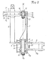
- FIGS 1 and 2 there is shown an embodiment of the device for detecting the position of a thrust reverser of a turbojet engine and of its locking comprising a support member fixed port 1 on which is pivotally mounted along an axis XX 1 a locking member 2 which consists of a stirrup having two branches 3, 3a between which is fixed an axis 4.
- a support member fixed port 1 on which is pivotally mounted along an axis XX 1
- a locking member 2 which consists of a stirrup having two branches 3, 3a between which is fixed an axis 4.
- the locking member On the side opposite the stirrup 3, 3a by relative to the axis XX 1 the locking member is extended by an arm 5 on which one of the ends of a rod 6 is fixed, the other end of which is secured to a second stirrup, the branches 7, 7a are engaged on the rod 6 and between which is hingedly mounted by means of an axis YY 1 a rod 8 of a control cylinder.
- the locking member 2 is pivotally mounted about the axis XX 1 on the support member 1 by means of a screw 9 engaged in a bore 10 of said member and in rings 11, 11a integral with the 'support member 1, said screw 9 being provided at one of its ends with a fixing nut 12.
- the second bracket 7, 7a is extended by a lug 13 having a bore 14 in which is engaged a screw 15 which is mounted by means of rings 16, 16a in the support member 1 on which it is fixed by means of a nut 17.
- the screws 9 and 15 are arranged coaxially along the axis XX ,, to ensure the pivoting of the assembly of the locking member 2.
- a hook 18 which is integral with the movable part of the reverser not shown in the drawing, said hook having a housing 18a in which is capable of being engaged l 'axis 4.
- 3a On an extension of the locking member 2 located on the side of the stirrup 3, 3a is fixed along an axis ZZ 1 parallel to the axis XX 1 a screw 19 around which is articulated a lever 20 having two arms 20a, 20b, one of which 20a is capable of coming into contact with the end 18b of the hook 18 and the other of which 20b is in contact with a roller 21 mounted to rotate at the end of a movable member 22 for controlling an electrical detection member 23 fixed to the support member 1 and the position of which can be adjusted by means of a screw 24 mounted on the support member 1.
- the arm 20b At its end which is in contact with the roller 21, the arm 20b has a rectilinear face 25 extended by a face 26 delimiting a recess, said faces 25 and 26 ensuring the guiding of the roller and controlling the movement of the control member 22 which is pushed back by a spring not shown in the drawing against said arm 20b of the lever 20 along the arrow F.
- the detector spring exerts a force F which applies a moment in the locking direction which is favorable to security against an unlocking caused by a fault in the cylinder, a rupture of the return spring for example. This effect is however slight because the spring force is weak.
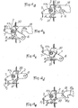
- FIG 3a the device is shown in its nominal position, when the movable part is retracted, all of the elements contributing to the locking of the hook 18 and of the movable part of the reverser.
- the hook 18 being pushed to the left, its end 18b is in contact with the arm 20a of the lever 20 which maintains by its arm 20b the roller 21 of the detector in position A which corresponds to the open electrical circuit, therefore to the absence of signaling , in particular by a light signal (lamp off).
- the hook 18 moves to the right and the axis 4 engages in the bottom of the housing 18a.
- the lever 20 which is no longer in contact with the end 18b of the hook 18 pivots about its axis ZZ 1 driven under the force of the spring of the detector which acts according to the arrow F.
- the arm 20a is then pressed against a stop member 27 secured to the locking member 2 and the movement of the lever 20 allows the roller 21 to occupy a position B for which the electrical circuit is closed, thus ensuring the lighting of a light signal.
- FIG. 4a the device is in its nominal starting position which has been described above and also shown in FIG. 3a; in this case, the jack exerts a force F 1 on the locking member 2.
- the jack is actuated and it exerts a force F 2 on the locking member 2 which rocks around the axis XX 1 thus releasing the hook 18 from the axis 4 mounted on said locking member.
- the hook 18 secured to the movable part remains in its initial position but unlocked, because the movable part remains in the retracted position.
- FIG. 4d which corresponds to the position of the deployed mobile part, the locking member is returned to the locking position by actuating the jack which exerts on it a force F 1 .
- the roller 21 is still in position B which corresponds to the closing of the circuit controlled by the detector 23 and the lighting of a light signal in particular.
- the electrical circuit is only opened when the hook 18 returns to the end of its travel (FIG. 4a) and its end 18b comes to bear against the arm 20a of the lever 20, the other arm 20b of which exerts pressure on the roller 21 which again occupies position A.
Landscapes
- Engineering & Computer Science (AREA)
- Chemical & Material Sciences (AREA)
- Combustion & Propulsion (AREA)
- Mechanical Engineering (AREA)
- General Engineering & Computer Science (AREA)
- Lock And Its Accessories (AREA)
- Mechanisms For Operating Contacts (AREA)
- Details Of Connecting Devices For Male And Female Coupling (AREA)
Claims (5)
Applications Claiming Priority (2)
| Application Number | Priority Date | Filing Date | Title |
|---|---|---|---|
| FR8017640 | 1980-08-11 | ||
| FR8017640A FR2488335B1 (fr) | 1980-08-11 | 1980-08-11 | Dispositif detecteur de position d'un inverseur de poussee de turboreacteur et de son verrouillage |
Publications (2)
| Publication Number | Publication Date |
|---|---|
| EP0046096A1 EP0046096A1 (de) | 1982-02-17 |
| EP0046096B1 true EP0046096B1 (de) | 1985-01-09 |
Family
ID=9245065
Family Applications (1)
| Application Number | Title | Priority Date | Filing Date |
|---|---|---|---|
| EP19810401163 Expired EP0046096B1 (de) | 1980-08-11 | 1981-07-22 | Einrichtung zur Bestimmung der Lage und der Verriegelung einer Schubumkehrvorrichtung eines Turboreaktors |
Country Status (5)
| Country | Link |
|---|---|
| US (1) | US4437783A (de) |
| EP (1) | EP0046096B1 (de) |
| JP (1) | JPS5759029A (de) |
| DE (1) | DE3168142D1 (de) |
| FR (1) | FR2488335B1 (de) |
Families Citing this family (35)
| Publication number | Priority date | Publication date | Assignee | Title |
|---|---|---|---|---|
| DE3222672C1 (de) * | 1982-06-16 | 1984-01-19 | MTU Motoren- und Turbinen-Union München GmbH, 8000 München | Einrichtung zum Verstellen von Schubumkehrern |
| US4827248A (en) * | 1987-06-30 | 1989-05-02 | The Boeing Company | Proximity sensor with automatic gap control |
| DE3938547A1 (de) * | 1989-11-21 | 1991-05-23 | Ford Werke Ag | Bauteilbefestigung in kraftfahrzeugkarosserien mit einer blechmutter und einem schraubenbolzen |
| FR2679605A1 (fr) * | 1991-07-24 | 1993-01-29 | Snecma | Inverseur de poussee de turboreacteur muni d'un dispositif de securite integre au systeme de commande hydraulique. |
| GB9215496D0 (en) * | 1992-07-21 | 1992-09-02 | Lucas Ind Plc | Lock for an engine thrust reverser |
| US5509747A (en) * | 1992-10-24 | 1996-04-23 | Deutsche Aerospace Ag | Articulation arrangement for connecting folding structure elements |
| FR2709017B1 (fr) * | 1993-08-12 | 1995-09-22 | Snecma | Circuit de détection de la position de plusieurs contacteurs bipolaires et application à un inverseur de poussée d'un turboréacteur. |
| GB9320447D0 (en) * | 1993-10-05 | 1993-12-22 | Lucas Ind Plc | Lock for an engine thrust reverser |
| US5720449A (en) * | 1993-11-19 | 1998-02-24 | Societe De Construction Des Avions Hurel-Dubois | Thrust reverser with doors for aircraft engine, equipped with safety systems preventing the untimely opening of the doors |
| FR2755730B1 (fr) * | 1996-11-14 | 1999-01-08 | Hispano Suiza Sa | Systeme de commande electrique pour inverseur de poussee de turboreacteur |
| US5813218A (en) * | 1996-11-26 | 1998-09-29 | Rooke Corp. | Thrust reverser door lock vent and method |
| FR2761733B1 (fr) * | 1997-04-03 | 1999-06-11 | Hispano Suiza Sa | Inverseur de poussee pour turbomoteur d'aeronef |
| FR2761734B1 (fr) * | 1997-04-03 | 1999-06-11 | Hispano Suiza Sa | Dispositif de fermeture et de verrouillage des obturateurs d'un inverseur de poussee |
| US6021636A (en) * | 1997-07-25 | 2000-02-08 | Alliedsignal Inc. | Lightweight tertiary thrust reverser lock assembly with a blocking member |
| US6042053A (en) * | 1997-10-31 | 2000-03-28 | The Boeing Company | Automatic restow system for aircraft thrust reverser |
| GB9907614D0 (en) * | 1999-04-06 | 1999-05-26 | Lucas Ind Plc | Lock for a thrust reverser |
| FR2823258B1 (fr) * | 2001-04-05 | 2003-09-19 | Hispano Suiza Sa | Systeme de verrouillage de secours pour porte d'inverseur de poussee |
| US6526744B2 (en) | 2001-04-30 | 2003-03-04 | Honeywell International Inc. | System and method for controlling the stowage of jet engine thrust reversers |
| US6519929B2 (en) | 2001-04-30 | 2003-02-18 | Honeywell International, Inc. | System and method for controlling the deployment of jet engine thrust reversers |
| US6439504B1 (en) | 2001-06-15 | 2002-08-27 | Honeywell International, Inc. | System and method for sustaining electric power during a momentary power interruption in an electric thrust reverser actuation system |
| US6681559B2 (en) | 2001-07-24 | 2004-01-27 | Honeywell International, Inc. | Thrust reverser position determination system and method |
| US6593758B2 (en) | 2001-08-02 | 2003-07-15 | Honeywell International Inc. | Built-in test system for aircraft indication switches |
| US6604355B1 (en) * | 2001-08-31 | 2003-08-12 | The Boeing Company | Thrust reverser hook latch system |
| US6684623B2 (en) | 2002-02-27 | 2004-02-03 | Honeywell International, Inc. | Gearless electric thrust reverser actuators and actuation system incorporating same |
| US6622963B1 (en) | 2002-04-16 | 2003-09-23 | Honeywell International Inc. | System and method for controlling the movement of an aircraft engine cowl door |
| FR2860554B1 (fr) * | 2003-10-06 | 2005-12-23 | Hurel Hispano | Verrou pour inverseur de poussee, muni d'un dispositif de blocage |
| GB0510424D0 (en) * | 2005-05-21 | 2005-06-29 | Smiths Group Plc | Restraining mechanisms |
| FR2887930B1 (fr) * | 2005-06-30 | 2007-08-17 | Snecma | Systeme de detection de fermeture et de verrouillage pour inverseur de poussee de turboreacteur |
| FR2970521B1 (fr) * | 2011-01-17 | 2013-01-04 | Aircelle Sa | Inverseur de poussee pour turboreacteur d'aeronef a nombre de verrous reduit |
| FR2998619B1 (fr) * | 2012-11-28 | 2021-05-07 | Aircelle Sa | Verrou actif avec assistance de mobilisation et inverseur de poussee incorporant un tel verrou |
| TWI467082B (zh) * | 2013-02-06 | 2015-01-01 | Great Computer Corp | 扣具 |
| CN103982494A (zh) * | 2013-02-07 | 2014-08-13 | 星云电脑股份有限公司 | 扣具 |
| US9109536B2 (en) | 2013-03-14 | 2015-08-18 | Woodward Hrt, Inc. | Engine thrust reverser lock |
| RU2669452C1 (ru) * | 2017-08-29 | 2018-10-11 | Акционерное общество "Объединенная двигателестроительная корпорация" (АО "ОДК") | Замок реверсивного устройства газотурбинного двигателя |
| US12215530B2 (en) * | 2022-06-10 | 2025-02-04 | Rohr, Inc. | Balk device for door lock |
Family Cites Families (9)
| Publication number | Priority date | Publication date | Assignee | Title |
|---|---|---|---|---|
| US2780057A (en) * | 1954-02-23 | 1957-02-05 | Boeing Co | Locks for jet thrust reversers |
| US2923127A (en) * | 1957-09-10 | 1960-02-02 | Curtiss Wright Corp | Jet engine exhaust nozzle limiting mechanism |
| NL247267A (de) * | 1958-04-02 | |||
| US2974904A (en) * | 1958-12-15 | 1961-03-14 | Lockheed Aircraft Corp | Control means for a blowing airflow over a control surface |
| GB921917A (en) * | 1961-05-31 | 1963-03-27 | Gen Electric | A control mechanism for the thrust reverser blocker doors of a jet propulsion engine |
| BE666798A (de) * | 1962-12-31 | 1965-11-03 | ||
| DE1287862B (de) * | 1963-09-26 | 1969-01-23 | ||
| US3460762A (en) | 1967-07-24 | 1969-08-12 | Mc Donnell Douglas Corp | Thrust reverser roller latch |
| US3618880A (en) | 1970-05-11 | 1971-11-09 | Boeing Co | Speed brake system for aircraft spoilers |
-
1980
- 1980-08-11 FR FR8017640A patent/FR2488335B1/fr not_active Expired
-
1981
- 1981-07-22 DE DE8181401163T patent/DE3168142D1/de not_active Expired
- 1981-07-22 EP EP19810401163 patent/EP0046096B1/de not_active Expired
- 1981-07-27 US US06/286,886 patent/US4437783A/en not_active Expired - Lifetime
- 1981-08-07 JP JP12391981A patent/JPS5759029A/ja active Granted
Also Published As
| Publication number | Publication date |
|---|---|
| EP0046096A1 (de) | 1982-02-17 |
| US4437783A (en) | 1984-03-20 |
| JPS5759029A (en) | 1982-04-09 |
| DE3168142D1 (en) | 1985-02-21 |
| FR2488335A1 (fr) | 1982-02-12 |
| FR2488335B1 (fr) | 1986-01-31 |
| JPS6133986B2 (de) | 1986-08-05 |
Similar Documents
| Publication | Publication Date | Title |
|---|---|---|
| EP0046096A1 (de) | Einrichtung zur Bestimmung der Lage und der Verriegelung einer Schubumkehrvorrichtung eines Turboreaktors | |
| EP0066486B1 (de) | Antriebsmechanismus für einen mehrpoligen Niederspannungs-Schutzschalter | |
| EP0593371B1 (de) | Antrieb für einen Dreistellungsschalter | |
| EP0534833A1 (de) | Verriegelungsvorrichtung mit Hakenriegel | |
| FR2575707A1 (fr) | Dispositif de detection de changement de vitesse pour la commande d'un embrayage associe a une boite de vitesses | |
| EP0206883B1 (de) | Lastschalter mit gegossenem Gehäuse | |
| CA2535327C (fr) | Verrou pour inverseur de poussee, muni d'un dispositif de bloquage | |
| EP2717284B1 (de) | Bedienungsvorrichtung eines elektrischen Schutzschaltgeräts, und diese umfassendes elektrisches Schutzschaltgerät | |
| EP1201851B1 (de) | Türgriffanordnung für eine Schiebetür eines Kraftfahrzeuges | |
| EP0313470B1 (de) | Kupplungsstange mit Kontakt für die Steuerung des Fluges eines Luftfahrzeuges | |
| FR2531129A1 (fr) | Commande exterieure de porte de vehicule equipee d'une serrure electrique | |
| FR2746957A1 (fr) | Mecanisme de commande d'un disjoncteur a grand angle d'ouverture | |
| EP0650178B1 (de) | Schnittstelle zur Anpassung für mehrpolige Differentialschalter | |
| EP0906997A1 (de) | Verriegelungsvorrichtung mit einem nockenbetätigten Übertragungselement | |
| FR2558511A1 (fr) | Dispositif d'ouverture automatique ou manuelle d'une porte de boite d'equipement de securite | |
| EP0032870B1 (de) | Auf ein Gestell montierbares Gerät zum Steuern der Bewegung eines Armes und Anwendung dieses Gerätes als Schalter | |
| CH666766A5 (fr) | Disjoncteur a contact escamotable telecommande en un point centre sur l'axe de deplacement de l'electro-aimant de telecommande. | |
| FR3098539A1 (fr) | Poignée d’ouvrant pour véhicule automobile | |
| FR2934244A1 (fr) | Boitier d'accrochage d'une charge | |
| FR2914073A1 (fr) | Montre a dispositif de commande et de verrouillage du remontoir | |
| FR2681633A1 (fr) | Dispositif de verrouillage de securite a crochet basculant. | |
| FR2696869A1 (fr) | Mécanisme pour sectionneur de mise à la terre. | |
| FR2858109A1 (fr) | Mecanisme de serrure a accrochage tournant pour coupe-circuit automatique de securite | |
| FR2646015A1 (fr) | Disjoncteur electrique | |
| FR2774771A1 (fr) | Dispositif formant testeur a pointe de touche retractable |
Legal Events
| Date | Code | Title | Description |
|---|---|---|---|
| PUAI | Public reference made under article 153(3) epc to a published international application that has entered the european phase |
Free format text: ORIGINAL CODE: 0009012 |
|
| 17P | Request for examination filed |
Effective date: 19810729 |
|
| AK | Designated contracting states |
Designated state(s): DE FR GB |
|
| GRAA | (expected) grant |
Free format text: ORIGINAL CODE: 0009210 |
|
| AK | Designated contracting states |
Designated state(s): DE FR GB |
|
| REF | Corresponds to: |
Ref document number: 3168142 Country of ref document: DE Date of ref document: 19850221 |
|
| PLBE | No opposition filed within time limit |
Free format text: ORIGINAL CODE: 0009261 |
|
| STAA | Information on the status of an ep patent application or granted ep patent |
Free format text: STATUS: NO OPPOSITION FILED WITHIN TIME LIMIT |
|
| 26N | No opposition filed | ||
| PGFP | Annual fee paid to national office [announced via postgrant information from national office to epo] |
Ref country code: DE Payment date: 19950929 Year of fee payment: 15 |
|
| PG25 | Lapsed in a contracting state [announced via postgrant information from national office to epo] |
Ref country code: DE Effective date: 19970402 |
|
| PGFP | Annual fee paid to national office [announced via postgrant information from national office to epo] |
Ref country code: FR Payment date: 19990621 Year of fee payment: 19 |
|
| PGFP | Annual fee paid to national office [announced via postgrant information from national office to epo] |
Ref country code: GB Payment date: 19990721 Year of fee payment: 19 |
|
| PG25 | Lapsed in a contracting state [announced via postgrant information from national office to epo] |
Ref country code: GB Free format text: LAPSE BECAUSE OF NON-PAYMENT OF DUE FEES Effective date: 20000722 |
|
| GBPC | Gb: european patent ceased through non-payment of renewal fee |
Effective date: 20000722 |
|
| PG25 | Lapsed in a contracting state [announced via postgrant information from national office to epo] |
Ref country code: FR Free format text: LAPSE BECAUSE OF NON-PAYMENT OF DUE FEES Effective date: 20010330 |
|
| REG | Reference to a national code |
Ref country code: FR Ref legal event code: ST |